

fireflyAIO-3399C主板LCD简介
描述
LCD使用
简介
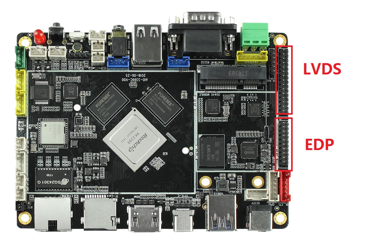
AIO-3399C开发板默认外置支持了两个LCD屏接口,一个是LVDS,一个是EDP,接口对应板子上的位置如下图:
另外板子也支持MIPI屏幕,但需要注意的是MIPI和LVDS是复用的,使用MIPI之后不能使用LVDS。需要客户自行焊接MIPI接口,如下图,还需要拆除红框内3排电阻拆掉: 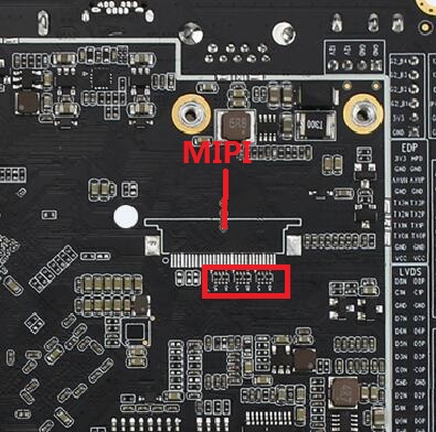
Config配置
以Android7.1为例,由于使用的是mipi转lvds,AIO-3399C默认的配置文件kernel/arch/arm64/configs/firefly_defconfig已经把LCD相关的配置设置好了,如果自己做了修改,请注意把以下配置加上:
CONFIG_LCD_MIPI=y CONFIG_MIPI_DSI=y CONFIG_RK32_MIPI_DSI=y
DTS配置
引脚配置
LVDS屏
AIO-3399C的SDK有LVDS DSI的DTS文件:kernel/arch/arm64/boot/dts/rockchip/rk3399-firefly-aioc-lvds.dts,从该文件中我们可以看到以下语句:
/ { model = “AIO Board lvds (Android)”; compatible = “rockchip,android”, “rockchip,rk3399-firefly-lvds”, “rockchip,rk3399”; test-power { status = “okay”; }; 。.. &dsi { status = “okay”; dsi_panel: panel { compatible =“simple-panel-dsi”; reg = 《0》; //ddc-i2c-bu //power-supply = 《&vcc_lcd》; //pinctrl-0 = 《&lcd_panel_reset &lcd_panel_enable》; backlight = 《&backlight》; /* enable-gpios = 《&gpio1 1 GPIO_ACTIVE_LOW》; reset-gpios = 《&gpio4 29 GPIO_ACTIVE_LOW》; */ dsi,flags = 《(MIPI_DSI_MODE_VIDEO | MIPI_DSI_MODE_VIDEO_BURST | MIPI_DSI_MODE_LPM | MIPI_DSI_MODE_EOT_PACKET)》; dsi,format = 《MIPI_DSI_FMT_RGB888》; //bus-format = 《MEDIA_BUS_FMT_RGB666_1X18》; dsi,lanes = 《4》; dsi,channel = 《0》; enable-delay-ms = 《35》; prepare-delay-ms = 《6》; unprepare-delay-ms = 《0》; disable-delay-ms = 《20》; size,width = 《120》; size,height = 《170》; status = “okay”; 。.. power_ctr: power_ctr { rockchip,debug = 《0》; power_enable = 《1》; lcd_en:lcd_en { gpios = 《&gpio2 5 GPIO_ACTIVE_HIGH》; pinctrl-names = “default”; pinctrl-0 = 《&lcd_panel_lcd_en》; rockchip,delay = 《10》; }; lcd_pwr_en: lcd-pwr-en { gpios = 《&gpio4 24 GPIO_ACTIVE_HIGH》; pinctrl-names = “default”; pinctrl-0 = 《&lcd_panel_pwr_en》; rockchip,delay = 《10》; }; lcd_rst: lcd-rst { gpios = 《&gpio4 25 GPIO_ACTIVE_HIGH》; pinctrl-names = “default”; pinctrl-0 = 《&lcd_panel_reset》; rockchip,delay = 《6》; }; }; 。.. &pinctrl { lcd-panel { lcd_panel_reset: lcd-panel-reset { rockchip,pins = 《4 25 RK_FUNC_GPIO &pcfg_pull_down》; }; lcd_panel_pwr_en: lcd-panel-pwr-en { rockchip,pins = 《4 24 RK_FUNC_GPIO &pcfg_pull_down》; }; lcd_panel_lcd_en:lcd_panel_lcd_en { rockchip,pins = 《2 5 RK_FUNC_GPIO &pcfg_pull_down》; }; }; };
这里定义了LCD的电源控制引脚:
lcd_en:(GPIO2_A5)GPIO_ACTIVE_HIGH lcd_pwr_en:(GPIO4_D0)GPIO_ACTIVE_HIGH lcd_rst:(GPIO4_D3)GPIO_ACTIVE_HIGH
都是高电平有效,具体的引脚配置请参考《GPIO》一节。
LVDS配置背光
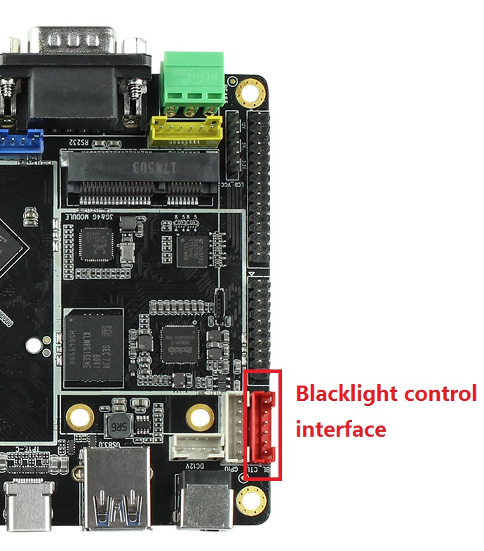
AIO-3399C开发板外置了一个背光接口用来控制屏幕背光,如下图所示:
在DTS文件:kernel/arch/arm64/boot/dts/rockchip/rk3399-firefly-core.dtsi中配置了背光信息,如下:
/ { compatible = “rockchip,rk3399-firefly-core”, “rockchip,rk3399”; backlight: backlight { status = “disabled”; compatible = “pwm-backlight”; pwms = 《&pwm0 0 25000 0》; brightness-levels = 《 0 1 2 3 4 5 6 7 8 9 10 11 12 13 14 15 16 17 18 19 20 21 22 23 24 25 26 27 28 29 30 31 32 33 34 35 36 37 38 39 40 41 42 43 44 45 46 47 48 49 50 51 52 53 54 55 56 57 58 59 60 61 62 63 64 65 66 67 68 69 70 71 72 73 74 75 76 77 78 79 80 81 82 83 84 85 86 87 88 89 90 91 92 93 94 95 96 97 98 99 100 101 102 103 104 105 106 107 108 109 110 111 112 113 114 115 116 117 118 119 120 121 122 123 124 125 126 127 128 129 130 131 132 133 134 135 136 137 138 139 140 141 142 143 144 145 146 147 148 149 150 151 152 153 154 155 156 157 158 159 160 161 162 163 164 165 166 167 168 169 170 171 172 173 174 175 176 177 178 179 180 181 182 183 184 185 186 187 188 189 190 191 192 193 194 195 196 197 198 199 200 201 202 203 204 205 206 207 208 209 210 211 212 213 214 215 216 217 218 219 220 221 222 223 224 225 226 227 228 229 230 231 232 233 234 235 236 237 238 239 240 241 242 243 244 245 246 247 248 249 250 251 252 253 254 255》; default-brightness-level = 《200》; };
pwms属性:配置PWM,范例里面默认使用pwm0,25000ns是周期(40 KHz)。LVDS需要加背光电源控制脚,在kernel/arch/arm64/boot/dts/rockchip/rk3399-firefly-aio-lvds.dts中可以看到以下语句:
&backlight { status = “okay”; enable-gpios = 《&gpio1 1 GPIO_ACTIVE_HIGH》; brightness-levels = 《 150 151 152 153 154 155 156 157 158 159 160 161 162 163 164 165 166 167 168 169 170 171 172 173 174 175 176 177 178 179 180 181 182 183 184 185 186 187 188 189 190 191 192 193 194 195 196 197 198 199 200 201 202 203 204 205 206 207 208 209 210 211 212 213 214 215 216 217 218 219 220 221 222 223 224 225 226 227 228 229 230 231 232 233 234 235 236 237 238 239 240 241 242 243 244 245 246 247 248 249 250 251 252 253 254 255》; };
因此使用时需修改DTS文件。
brightness-levels属性:配置背光亮度数组,最大值为255,配置暗区和亮区,并把亮区数组做255的比例调节。比如范例中暗区是255-221,亮区是220-0。 default-brightness-level属性:开机时默认背光亮度,范围为0-255。 具体请参考kernel中的说明文档:kernel/Documentation/devicetree/bindings/leds/backlight/pwm-backlight.txt
配置显示时序
LVDS屏
与EDP屏不同,LVDS屏的 Timing 写在DTS文件中,在kernel/arch/arm64/boot/dts/rockchip/rk3399-firefly-aioc-lvds.dts中可以看到以下语句:
disp_timings: display-timings { native-mode = 《&timing0》; timing0: timing0 { clock-frequency = 《150000000》; //166000000 @50 hactive = 《1920》; vactive = 《1080》; hsync-len = 《10》; //20, 50 hback-porch = 《10》; //50, 56 hfront-porch = 《282》;//50, 30 //1580 vsync-len = 《10》; vback-porch = 《25》; vfront-porch = 《10》; hsync-active = 《0》; vsync-active = 《0》; de-active = 《0》; pixelclk-active = 《0》; }; };
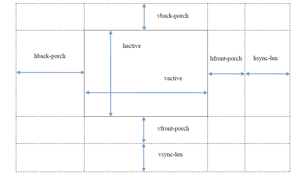
时序属性参考下图:
Init Code
LVDS屏
lvds屏上完电后需要发送初始化指令才能使之工作。
dts 可以在kernel/arch/arm64/boot/dts/rockchip/rk3399-firefly-aioc-lvds.dts中可以看到lvds的初始化指令列表:
&dsi { status = “okay”; 。.. panel-init-sequence = [ 29 00 06 3C 01 09 00 07 00 29 00 06 14 01 06 00 00 00 29 00 06 64 01 0B 00 00 00 29 00 06 68 01 0B 00 00 00 29 00 06 6C 01 0B 00 00 00 29 00 06 70 01 0B 00 00 00 29 00 06 34 01 1F 00 00 00 29 00 06 10 02 1F 00 00 00 29 00 06 04 01 01 00 00 00 29 00 06 04 02 01 00 00 00 29 00 06 50 04 20 01 F0 03 29 00 06 54 04 32 00 B4 00 29 00 06 58 04 80 07 48 00 29 00 06 5C 04 0A 00 19 00 29 00 06 60 04 38 04 0A 00 29 00 06 64 04 01 00 00 00 29 01 06 A0 04 06 80 44 00 29 00 06 A0 04 06 80 04 00 29 00 06 04 05 04 00 00 00 29 00 06 80 04 00 01 02 03 29 00 06 84 04 04 07 05 08 29 00 06 88 04 09 0A 0E 0F 29 00 06 8C 04 0B 0C 0D 10 29 00 06 90 04 16 17 11 12 29 00 06 94 04 13 14 15 1B 29 00 06 98 04 18 19 1A 06 29 02 06 9C 04 33 04 00 00 ]; panel-exit-sequence = [ 05 05 01 28 05 78 01 10 ]; 。.. };
命令格式以及说明可参考以下附件: Rockchip DRM Panel Porting Guide.pdf
kernel 发送指令可以看到在kernel/drivers/gpu/drm/panel/panel-simple.c文件中的操作:
static int panel_simple_enable(struct drm_panel *panel) { struct panel_simple *p = to_panel_simple(panel); int err; if (p-》enabled) return 0; DBG(“enter\n”); if (p-》on_cmds) { err = panel_simple_dsi_send_cmds(p, p-》on_cmds); if (err) dev_err(p-》dev, “failed to send on cmds\n”); } if (p-》desc && p-》desc-》delay.enable) { DBG(“p-》desc-》delay.enable=%d\n”, p-》desc-》delay.enable); msleep(p-》desc-》delay.enable); } if (p-》backlight) { DBG(“open backlight\n”); p-》backlight-》props.power = FB_BLANK_UNBLANK; backlight_update_status(p-》backlight); } p-》enabled = true; return 0; }
u-boot 发送指令可以看到在u-boot/drivers/video/rockchip-dw-mipi-dsi.c文件中的操作:
static int rockchip_dw_mipi_dsi_enable(struct display_state *state) { struct connector_state *conn_state = &state-》conn_state; struct crtc_state *crtc_state = &state-》crtc_state; const struct rockchip_connector *connector = conn_state-》connector; const struct dw_mipi_dsi_plat_data *pdata = connector-》data; struct dw_mipi_dsi *dsi = conn_state-》private; u32 val; DBG(“enter\n”); dw_mipi_dsi_set_mode(dsi, DW_MIPI_DSI_VID_MODE); dsi_write(dsi, DSI_MODE_CFG, ENABLE_CMD_MODE); dw_mipi_dsi_set_mode(dsi, DW_MIPI_DSI_VID_MODE); if (!pdata-》has_vop_sel) return 0; if (pdata-》grf_switch_reg) { if (crtc_state-》crtc_id) val = pdata-》dsi0_en_bit | (pdata-》dsi0_en_bit 《《 16); else val = pdata-》dsi0_en_bit 《《 16; writel(val, RKIO_GRF_PHYS + pdata-》grf_switch_reg); } debug(“vop %s output to dsi0\n”, (crtc_state-》crtc_id) ? “LIT” : “BIG”); //rockchip_dw_mipi_dsi_read_allregs(dsi); return 0; }
DTS配置
引脚配置
EDP屏
AIO-3399C的SDK有EDP DSI的DTS文件:kernel/arch/arm64/boot/dts/rockchip/rk3399-firefly-aioc-edp.dts,从该文件中我们可以看到以下语句:
edp_panel: edp-panel { /* config 2 */ compatible = “lg,lp079qx1-sp0v”; /* config 3 */ //compatible = “simple-panel”; bus-format = ; backlight = 《&backlight》; ports { panel_in_edp: endpoint { remote-endpoint = 《&edp_out_panel》; }; }; power_ctr: power_ctr { rockchip,debug = 《0》; lcd_en: lcd-en { gpios = 《&gpio1 1 GPIO_ACTIVE_HIGH》; pinctrl-names = “default”; pinctrl-0 = 《&lcd_panel_enable》; rockchip,delay = 《20》; }; lcd_rst: lcd-rst { gpios = 《&gpio4 29 GPIO_ACTIVE_HIGH》; pinctrl-names = “default”; pinctrl-0 = 《&lcd_panel_reset》; rockchip,delay = 《20》; }; lcd_pwr_en: lcd-pwr-en { gpios = 《&gpio2 5 GPIO_ACTIVE_HIGH》; pinctrl-names = “default”; pinctrl-0 = 《&lcd_panel_pwr_en》; rockchip,delay = 《10》; }; sys_5v_en: sys-5v-en { gpios = 《&gpio1 23 GPIO_ACTIVE_HIGH》; pinctrl-names = “default”; pinctrl-0 = 《&host_hub_vcc》; rockchip,delay = 《10》; }; }; }; ··· &pinctrl { lcd-panel { lcd_panel_reset: lcd-panel-reset { rockchip,pins = 《4 29 RK_FUNC_GPIO &pcfg_pull_up》; }; lcd_panel_enable: lcd-panel-enable { rockchip,pins = 《1 1 RK_FUNC_GPIO &pcfg_pull_up》; }; lcd_panel_pwr_en: lcd-panel-pwr-en { rockchip,pins = 《2 5 RK_FUNC_GPIO &pcfg_pull_up》; }; }; };
这里定义了LCD的电源控制引脚:
lcd_en:(GPIO1_A1)GPIO_ACTIVE_HIGH lcd_rst:(GPIO4_D5)GPIO_ACTIVE_HIGH
都是高电平有效,具体的引脚配置请参考《GPIO》一节。
EDP配置背光
因为背光接口是公用的,所以可参考上述LVDS的配置方法。
EDP配置显示时序
kernel 把 Timing 写在 panel-simple.c 中, 直接以短字符串匹配 在drivers/gpu/drm/panel/panel-simple.c文件中有以下语句
static const struct drm_display_mode lg_lp079qx1_sp0v_mode = { .clock = 200000, .hdisplay = 1536, .hsync_start = 1536 + 12, .hsync_end = 1536 + 12 + 16, .htotal = 1536 + 12 + 16 + 48, .vdisplay = 2048, .vsync_start = 2048 + 8, .vsync_end = 2048 + 8 + 4, .vtotal = 2048 + 8 + 4 + 8, .vrefresh = 60, .flags = DRM_MODE_FLAG_NVSYNC | DRM_MODE_FLAG_NHSYNC, }; static const struct panel_desc lg_lp097qx1_spa1 = { .modes = &lg_lp097qx1_spa1_mode, .num_modes = 1, .size = { .width = 320, .height = 187, }, }; 。.. 。.. static const struct of_device_id platform_of_match[] = { { .compatible = “simple-panel”, .data = NULL, },{ }, { .compatible = “lg,lp079qx1-sp0v”, .data = &lg_lp079qx1_sp0v, }, { }, { /* sentinel */ } };
MODULE_DEVICE_TABLE(of, platform_of_match); 时序的参数在结构体lg_lp079qx1_sp0v_mode中配置。
*U-boot 把 Timing 写在 rockchip_panel.c 中, 直接以短字符串匹配 在drivers/video/rockchip_panel.c文件中有以下语句:
static const struct drm_display_mode lg_lp079qx1_sp0v_mode = { .clock = 200000, .hdisplay = 1536, .hsync_start = 1536 + 12, .hsync_end = 1536 + 12 + 16, .htotal = 1536 + 12 + 16 + 48, .vdisplay = 2048, .vsync_start = 2048 + 8, .vsync_end = 2048 + 8 + 4, .vtotal = 2048 + 8 + 4 + 8, .vrefresh = 60, .flags = DRM_MODE_FLAG_NVSYNC | DRM_MODE_FLAG_NHSYNC, }; static const struct rockchip_panel g_panel[] = { { .compatible = “lg,lp079qx1-sp0v”, .mode = &lg_lp079qx1_sp0v_mode, }, { .compatible = “auo,b125han03”, .mode = &auo_b125han03_mode, }, };
时序的参数在结构体lg_lp079qx1_sp0v_mode中配置。
MIPI屏
客户根据需要在自行添加mipi硬件接口之后,配置MIPI屏的 Timing dts文件,在kernel/arch/arm64/boot/dts/rockchip/rk3399-firefly-aioc-mipi.dts中可以看到以下语句:
disp_timings: display-timings { native-mode = 《&timing0》; timing0: timing0 { clock-frequency = 《80000000》; hactive = 《768》; vactive = 《1024》; hsync-len = 《20》; //20, 50 hback-porch = 《130》; //50, 56 hfront-porch = 《150》;//50, 30 vsync-len = 《40》; vback-porch = 《130》; vfront-porch = 《136》; hsync-active = 《0》; vsync-active = 《0》; de-active = 《0》; pixelclk-active = 《0》; }; } }
Kernel 在kernel/drivers/gpu/drm/panel/panel-simple.c中可以看到在初始化函数panel_simple_probe中初始化了获取时序的函数。
static int panel_simple_probe(struct device *dev, const struct panel_desc *desc){ ··· panel-》base.funcs = &panel_simple_funcs; ··· }
该函数的在kernel/drivers/gpu/drm/panel/panel-simple.c中也有定义:
static int panel_simple_get_timings(struct drm_panel *panel,unsigned int num_timings,struct display_timing *timings) { struct panel_simple *p = to_panel_simple(panel); unsigned int i; if (!p-》desc) return 0; if (p-》desc-》num_timings 《 num_timings) num_timings = p-》desc-》num_timings; if (timings) for (i = 0; i 《 num_timings; i++) timings[i] = p-》desc-》timings[i]; return p-》desc-》num_timings; }
mipi屏上完电后需要发送初始化指令才能使之工作,可以在kernel/arch/arm64/boot/dts/rockchip/rk3399-firefly-mipi.dts中可以看到mipi的初始化指令列表:
&mipi_dsi { status = “okay”; 。.. panel-init-sequence = [ 05 20 01 29 05 96 01 11 ]; panel-exit-sequence = [ 05 05 01 28 05 78 01 10 ]; 。.. };
命令格式以及说明可参考以下附件: Rockchip DRM Panel Porting Guide.pdf
发送指令可以看到在kernel/drivers/gpu/drm/panel/panel-simple.c文件中的操作:
static int panel_simple_enable(struct drm_panel *panel) { struct panel_simple *p = to_panel_simple(panel); int err; if (p-》enabled) return 0; DBG(“enter\n”); if (p-》on_cmds) { err = panel_simple_dsi_send_cmds(p, p-》on_cmds); if (err) dev_err(p-》dev, “failed to send on cmds\n”); } if (p-》desc && p-》desc-》delay.enable) { DBG(“p-》desc-》delay.enable=%d\n”, p-》desc-》delay.enable); msleep(p-》desc-》delay.enable); } if (p-》backlight) { DBG(“open backlight\n”); p-》backlight-》props.power = FB_BLANK_UNBLANK; backlight_update_status(p-》backlight); } p-》enabled = true; return 0; }
U-boot 发送指令可以看到在u-boot/drivers/video/rockchip-dw-mipi-dsi.c文件中的操作:
static int rockchip_dw_mipi_dsi_enable(struct display_state *state) { struct connector_state *conn_state = &state-》conn_state; struct crtc_state *crtc_state = &state-》crtc_state; const struct rockchip_connector *connector = conn_state-》connector; const struct dw_mipi_dsi_plat_data *pdata = connector-》data; struct dw_mipi_dsi *dsi = conn_state-》private; u32 val; DBG(“enter\n”); dw_mipi_dsi_set_mode(dsi, DW_MIPI_DSI_VID_MODE); dsi_write(dsi, DSI_MODE_CFG, ENABLE_CMD_MODE); dw_mipi_dsi_set_mode(dsi, DW_MIPI_DSI_VID_MODE); if (!pdata-》has_vop_sel) return 0; if (pdata-》grf_switch_reg) { if (crtc_state-》crtc_id) val = pdata-》dsi0_en_bit | (pdata-》dsi0_en_bit 《《 16); else val = pdata-》dsi0_en_bit 《《 16; writel(val, RKIO_GRF_PHYS + pdata-》grf_switch_reg); } debug(“vop %s output to dsi0\n”, (crtc_state-》crtc_id) ? “LIT” : “BIG”); //rockchip_dw_mipi_dsi_read_allregs(dsi); return 0; }
-
fireflyAIO-3399C主板IR简介2019-12-13 2564
-
fireflyAIO-3399C主板散热介绍2019-12-09 2077
-
fireflyAIO-3399C主板FAQs方案2019-12-04 2252
全部0条评论

快来发表一下你的评论吧 !
