
MAX2659 GPS LNA优于十款同类产品 (MAX26
IC应用电路图
506人已加入
描述
MAX2659 GPS LNA优于十款同类产品-MAX2659 GPS LNA Outperforms Ten Competitive Parts
Abstract: This application note objectively compares performance and solution size/cost of the MAX2659 GPS LNA against 10 current competing GPS LNA products. Figures of merit such as gain-current efficiency, output power efficiency, and GPS input signal dynamic range are used for comparative evaluation. Purpose of This ReportThe MAX2659 was developed for mobile/handheld equipment to meet the size and solution cost requirements of low-cost consumer electronics equipment. It was designed to outperform all other low-cost, high-performance handheld GPS LNAs.Due to highly positive reports from Maxim's IC design engineers, Maxim's Application Engineering group decided to test whether this new LNA indeed lived up to such encouraging reports. Therefore, we set up a comparison, including GPS LNAs from both Maxim and the competition that had roughly similar performance and existed in our customer's designs. We looked for:
Performance Figures of MeritThere are many ways to compare RF amplifiers, and we selected metrics that are objective, measurable, and focus on low power, high gain, and dynamic range. We decided that the most meaningful figures of merit for a comparison of GPS LNAs were:
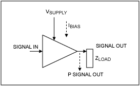
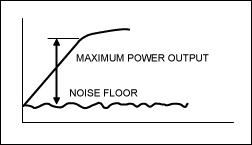
Gain-Current Efficiency (dB Gain/mA)A traditional way to assess an amplifier's "enthusiasm", or responsiveness, can be made by measuring the ratio of its signal gain to the DC energy applied. For example, transconductance is the traditional responsiveness figure-of-merit used for comparing individual semiconductor transistor devices. For comparing a group of LNAs, we use gain-current efficiency.For our comparison, we calculated the dB gain available for the standing bias current. The less current required to obtain higher gain, the better the LNA's gain-current efficiency. A 20dB amplifier that draws 5mA bias current has a figure of merit equal to 4.0dB/mA. Output-Power Efficiency (% Ratio P1dB/PDISS)Output-power efficiency is important for comparing how the LNA manages large interfering signals Figure 1. Typical amplifier signals. We use a ratio of the output-signal compression point (P1dB), to the total power dissipated (PDISS). Suppose an amplifier has an input P1dB compression point (IP1dB) of -20dBm and a gain of 17dB, we estimate its P1dB at -3dBm, or 0.5mW. If that amplifier drew 5mA from 3V supply, its PDISS would be 15mW, and the % output-power efficiency is calculated at: 0.5/15 = 3.3% This represents a mediocre performance figure for a GPS LNA, as Table 1 shows. Note that, if the amplifier's IP1dB was higher at -12dBm, then P1dB could be estimated at +5dBm or 7mW, and the output-power efficiency would increase to 5%. GPS Input-Signal Dynamic Range in dBSpurious-free dynamic range (as in Figure 2) indicates ability to handle very small signals in the presence of large interferers—for GPS input amplifiers, this capability is very important. Figure 2. Spurious-free dynamic range. Typical signals levels that are expected at the LNA output include antenna (source) thermal noise gained up by the LNA (plus noise figure) and any narrowband interfering signals. For GPS processing, we will assume 2MHz RF noise bandwidth (BW), which is the typical GPS-under-noise signal BW presented to the baseband digital processor. However, it is certainly possible to gather more spectral width (military systems) or less BW (less than around 1.5MHz BW begins to throw away valuable signal power). We also assume a mild input filter with roughly 100MHz of RF BW that greatly suppresses cellular, PCS, and Wi-Fi band signals from co-located transmitters. The following are gained up to form the LNA's output spectrum:
Therefore, we specified the dynamic range figure of merit as P1dB minus output NF in dB. Passive Circuit Parts CountThe number of external matching and power-supply decoupling components figures into the decision for designing in an LNA, even though these parts costs represent a small fraction of the overall solution cost. The main objection to having many external parts is circuit performance variation and circuit size. For this reason, Avago™ integrated a GPS bandpass filter into its ALM-1412 LNA. However, as we found out during this exercise, lackluster performance in other areas detracted from it being a clear performance leader.Results of the MAX2659 LNA ComparisonHere we show two tables of LNA performance, representing competitive 10 LNAs that we have seen in commercial consumer-product use, roughly in the same class as the MAX2659.Note that we sought datasheets from the web, and the figures we present here are as accurate as we were able to obtain through normal public advertisement channels. In the case of some of these devices, there may be improved versions, but the models presented here are what we have run across in our regular work over roughly the past year. Table 1. GPS LNA Competitive Vendors Performance Comparison (1575MHz Data) Note: Specifications are data sheet "typical" performance.
Comparing Gain-Current Efficiency (dB Gain/mA)Originally, we had thought that the higher-gain LNAs would probably fare best in this comparison, but that is not the case. Consider for example the MAX2641, an older but popular SiGe LNA introduced in 1998—it has an excellent 4.49dB/mA gain efficiency, but a gain of only 15.7dB.The best of the group was New Japan Radio's NJG1107 at 6.8dB/mA gain efficiency, due to its low bias current of only 2.5mA. The worst were the Avago LNAs with less than 2dB/mA gain-current efficiency. Overall the MAX2659 fared acceptably at 5.0dB/mA, where it ranks fifth from the top, placing it among the upper group of LNAs. Four of its peers have quite a similar gain efficiency. Comparing Output Power Efficiency (% Ratio P1dB/PDISS)Here the MAX2659 really shines; it is clearly the best in its class. Most of the LNAs we investigated had 3% to 7% power-efficiency range. However, the MAX2659 provides an excellent 54% due to its high P1dB and modest power dissipation. Several peers offer 15% to 20% power efficiency.Comparing Signal Dynamic Range in dBThe Avago ALM-1412 with integrated GPS bandpass filter ranked first in dynamic range at 100.5dB. The MAX2659 and the other Avago LNA we compared tied for second place at 97.7dB, about 3dB less than the ALM-1412. The lowest dynamic range we observed was 88.2dB for NEC's uP8321. Most LNAs we looked at appeared to offer roughly 91dB to 95dB of signal dynamic range.Comparing Passive Circuit Parts CountWe obtained our external passive parts count by examining the datasheets and/or application circuit provided on the web and, in some cases, there may be lower parts count circuits than we were able to find. However, it is important to note that we represent typical RF application engineers looking through the web for data when making our decisions.As most LNAs require six or seven external parts, the MAX2659's requirement of only three external parts makes it the clear leader for use in small design solutions. Summary of Our GPS LNA Competitive SurveyAll of the LNAs presented here offer some value, whether in price, size, or electrical performance. However, the MAX2659 not only has competitive features, but it is also priced "to compete aggressively."Therefore, we ended up agreeing with the IC design engineers' claims that the MAX2659 is the best overall in its class, as it:
Avago is a trademark of Avago Technologies Ltd. |
声明:本文内容及配图由入驻作者撰写或者入驻合作网站授权转载。文章观点仅代表作者本人,不代表电子发烧友网立场。文章及其配图仅供工程师学习之用,如有内容侵权或者其他违规问题,请联系本站处理。
举报投诉
-
MAX2659:GPS/GNSS低噪声放大器的卓越之选2026-01-06 91
-
MAX2659 GPS/GNSS低噪声放大器技术手册2025-03-18 1256
-
MAX2659ELT+T 射频放大器2023-02-03 150
-
L1频段卫星导航射频前端低噪声放大器MS2659系列(LNA)芯片2021-11-08 952
-
如何铺求GPS无源天线PCB设计?2019-08-21 6583
-
HONDA推出两款户外便携电源 其中小容量版是同类产品中非常轻量的2018-12-06 2029
-
基于MAX2641的GPS接收机LNA电路2018-05-06 5529
-
阿里达摩院宣布研发AI芯片性价比是同类产品40倍2018-04-20 5225
-
MAX2687,MAX2689低噪声放大器(LNA)2012-04-16 4233
-
美信推出MAX2686/MAX2688低噪声系数LNA GPS/GNSS放大器2011-02-01 1861
-
具有升压功能的GPS超低噪声放大器MAX2667/MAX262010-12-23 1131
-
MAX2657, MAX2658 微型LNA有效改善GPS接2009-12-17 1240
-
MAX2654, MAX2655, MAX2656 15752008-12-13 1315
-
MAX2659 pdf2008-06-30 2479
全部0条评论

快来发表一下你的评论吧 !

