

DVB-S Half-NIM Tuner Reference
IC应用电路图
512人已加入
描述
DVB-S Half-NIM Tuner Reference Design Uses the MAX2120 Tuner
Abstract: This reference design is a commercial Half-NIM DVB-S tuner that uses Maxim's MAX2120 satellite tuner IC. The reference design connects to the motherboard through a 12-pin connector. The downconverted satellite signal from the LNB is supplied to an active, discrete loop-through, which splits the signal into two paths. One signal goes to the MAX2120 and the other provides an additional output from the STB. 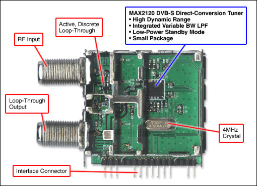
Figure 1. DVB-S Half-NIM reference design features the MAX2120 tuner.
| Important Design Features |
- A Popular Form Factor Often Used in the Chinese DVB-S Market; Can Be Adopted Without Physical Modifications
- Active Loop-Through Using a Discrete LNA
- LNB 12V Power Feed-Through
Figure 2. System block diagram.
| Lab Measurements |
|
| System Performance |
DVB-S system measurements for the MAX2120 Half-NIM are made by connecting to a DVB-S demodulator.
Figure 3. The DVB-S sensitivity without noise is better than -92.5dBm for 4.42Msps, and better than -84dBm for 27.5Msps across the band.
Figure 4. When noise is added, the DVB-S sensitivity is better than -85dBm for 4.42Msps, and better than
| Detailed Description |
This MAX2120 reference design is a compact Half-NIM DVB-S tuner for satellite STB applications. The design covers the RF range from 925MHz to 2175MHz. The MAX2120 is a fully integrated silicon tuner, which includes a LNA, RF and IF VGAs, a mixer, and a variable-bandwidth LPF in the baseband stage. The tuner is powered by a single 3.3V supply. A small number of passive components are needed to form a complete DVB-S RF front-end solution.
声明:本文内容及配图由入驻作者撰写或者入驻合作网站授权转载。文章观点仅代表作者本人,不代表电子发烧友网立场。文章及其配图仅供工程师学习之用,如有内容侵权或者其他违规问题,请联系本站处理。
举报投诉
- 相关推荐
- 热点推荐
- MAX2120
-
DVB-S半NIM调谐器参考设计采用MAX2120调谐器2023-06-10 2209
-
EMMA2SL/P DVB-S 参考板2023-05-04 465
-
基于MAX2120卫星调谐器IC的Half-NIM DVB-S调谐器2021-04-15 2860
-
请问哪里可以下载电视卫星(DVB-S)数据?2019-12-05 1888
-
自制收视创意设备--DVB-S、ABS-S收视一体机2017-12-12 2697
-
Turbo码在DVB-S系统中的应用研究2012-02-27 914
-
DVB-S机顶盒电路原理图2011-04-11 6490
-
国内外主流DVB-S ,DVB-S2及ISDBT 方案,功能2010-10-28 3887
-
高价寻找DVB-S方案!2009-10-10 3967
-
谁有DVB-S的DEMO方案,我购买2009-02-09 3142
-
DVB-S/DVB-S2信号发生器 (DVB-S/S2 Si2009-01-15 1126
-
GX1101是国产首款支持DVB-S标准的卫星数字电视信道解2008-09-24 2039
-
MAX3580 DVB-T Reference Design2008-08-18 2377
全部0条评论

快来发表一下你的评论吧 !
