

Satellite Radio Receiver 1st M
RF/无线
1841人已加入
描述
Abstract: The MAX2682 miniature, low-cost, low-noise downconverter is designed for low-voltage operation and is ideal for use in portable communications equipment. Signals at the RF input port are mixed with signals at the local oscillator (LO) port using a double-balanced mixer. This downconverter operates with RF input frequencies between 400MHz and 2500MHz, and downconverts to IF output frequencies between 10MHz and 500MHz
Additional Information:
The MAX2682 downconverter operates from a single +2.7V to +5.5V supply, ideal for hand held applications. Each downconverter features a low-power shutdown mode in which it typically draws less than 0.1µA of supply current.
The MAX2682 downconverter is manufactured on a high-frequency, low-noise, advanced silicon-germanium process and is offered in the space-saving 6-pin SOT23 package.
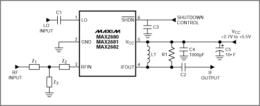
Figure 1. Typical operating circuit (the values of matching components C2, L1, R1, Z1, Z2, and Z3 depend on the IF and RF frequency and downconverter).
The MAX2682 mixer has been retuned for the following parameters:
1. RF = 2642.5MHz
2. IF = 402.5MHz
3. LO frequency = 3045MHz
4. BW (bandwidth) = 25MHz
5. Vcc = 3.3V
Figure 2 shows the matching networks used to make all measurements in this report.
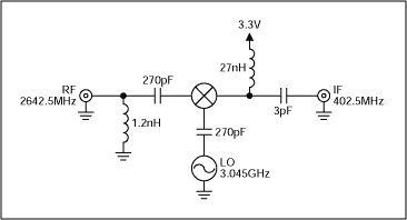
Figure 2. Matching network for 2642.5MHz satellite radio.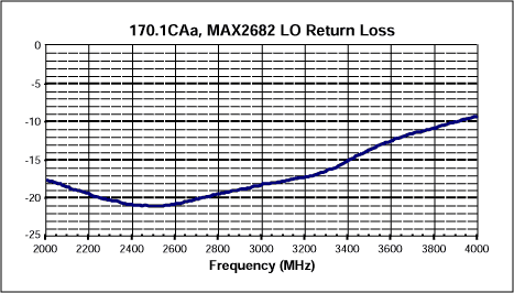
Figure 3. LO port return loss.
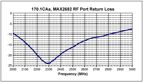
Figure 4. RF port return loss.
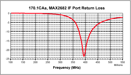
Figure 5. IF port return loss.
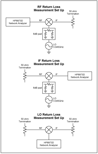
Figure 6. Return loss measurement set up.
Figure 7 shows very flat gain, down only 0.2dB at 12.5MHz band edge.
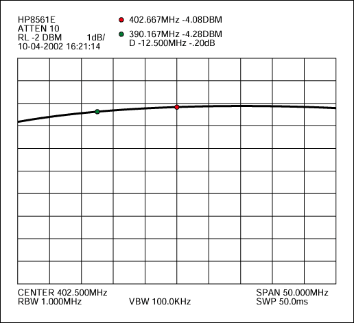
Figure 7. Gain flatness.
LO – RF = 16.67dB
Below is the raw data taken for the isolation measurement.
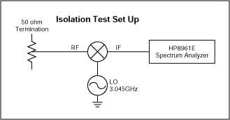
Figure 8. Test set up used for isolation measurement.
Table 1 below contains the noise figure data for the MAX2682 versus LO power level.
Table 1. Noise Figure Data
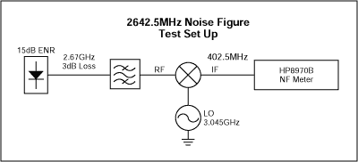
Figure 9. Noise figure test set up.
The signal generator used to provide the LO (3.045GHz) is the HP8638C.
打开APP阅读更多精彩内容
Additional Information:
- Wireless Product Line Page
- MAX2680/MAX2681/MAX2682
- The MAX2140 Complete SDARS Receiver
- The MAX2472/MAX2473 500MHz to 2500MHz VCO Buffer Amplifiers
- Applications Technical Support
MAX2682 Description
The MAX2682 is a miniature, low-cost, low-noise downconverter designed for low-voltage operation and is ideal for use in portable communications equipment. Signals at the RF input port are mixed with signals at the LO port using a double-balanced mixer. This downconverter operates with RF input frequencies between 400MHz and 2500MHz, and downconverts to IF output frequencies between 10MHz and 500MHz.The MAX2682 downconverter operates from a single +2.7V to +5.5V supply, ideal for hand held applications. Each downconverter features a low-power shutdown mode in which it typically draws less than 0.1µA of supply current.
The MAX2682 downconverter is manufactured on a high-frequency, low-noise, advanced silicon-germanium process and is offered in the space-saving 6-pin SOT23 package.

Figure 1. Typical operating circuit (the values of matching components C2, L1, R1, Z1, Z2, and Z3 depend on the IF and RF frequency and downconverter).
The MAX2682 mixer has been retuned for the following parameters:
1. RF = 2642.5MHz
2. IF = 402.5MHz
3. LO frequency = 3045MHz
4. BW (bandwidth) = 25MHz
5. Vcc = 3.3V
Figure 2 shows the matching networks used to make all measurements in this report.

Figure 2. Matching network for 2642.5MHz satellite radio.
Measured Performance

Figure 3. LO port return loss.

Figure 4. RF port return loss.

Figure 5. IF port return loss.

Figure 6. Return loss measurement set up.
Figure 7 shows very flat gain, down only 0.2dB at 12.5MHz band edge.

Figure 7. Gain flatness.
Isolation
LO – IF = 10.67dBLO – RF = 16.67dB
Below is the raw data taken for the isolation measurement.
|
LO IF Isolation | ||
|
-5dBm |
-15.67dBm |
10.67dB |
|
LO RF Isolation | ||
|
-5dBm |
-21.67dBm |
16.67dB |

Figure 8. Test set up used for isolation measurement.
Table 1 below contains the noise figure data for the MAX2682 versus LO power level.
Table 1. Noise Figure Data
|
LO Power (dBm) |
Gain (dB) |
NF (dB) |
|
0 |
7.3 |
11.86 |
|
-1 |
7.26 |
12.1 |
|
-2 |
7.17 |
12.36 |
|
-3 |
7.05 |
12.64 |
|
-4 |
6.86 |
12.97 |
|
-5 |
6.56 |
13.3 |
|
-6 |
6.2 |
13.73 |

Figure 9. Noise figure test set up.
The signal generator used to provide the LO (3.045GHz) is the HP8638C.
声明:本文内容及配图由入驻作者撰写或者入驻合作网站授权转载。文章观点仅代表作者本人,不代表电子发烧友网立场。文章及其配图仅供工程师学习之用,如有内容侵权或者其他违规问题,请联系本站处理。
举报投诉
- 相关推荐
- 热点推荐
- M
-
亿纬锂能受邀出席The 1st SNE Battery Day2024-07-27 1340
-
EC-NE3509M04 2.4 GHz LNA 评估板 for Satellite Radio Application(SDARS) Ver3 EB2023-05-08 359
-
EC-NE3508M04 2.4 GHz LNA 评估板 for Satellite Radio Application(OIP3 optimized) EB2023-05-05 288
-
CAT-M1-ST814D CAT-M1-ST814D 标准圆形连接器2021-07-15 222
-
CAT-M1-ST814 CAT-M1-ST814 标准圆形连接器2021-07-13 202
-
DC Circuits, 1st Edition - Davis, 20162021-06-23 1315
-
ST730M33R STMicroelectronics ST730低压差LDO稳压器2020-10-29 663
-
ST32F512M ST32F512M对于M2M ST32安全微2020-05-20 839
-
DSP based Coherent Receiver fo2010-07-01 960
-
Broadband Satellite Access2009-11-28 667
全部0条评论

快来发表一下你的评论吧 !

