
Flexible Fault Protection
应用电子电路
描述
Many applications require the capability to automatically disconnect power from an operating circuit. Such applications include thermal shutdown of high-voltage power supplies in radar and X-ray systems, shutdown to limit inrush current during power-up or hot-swapping of pc cards, and shutdown to ensure that a card is properly seated before power is applied. In general, a power fault system will keep the power off following the system fault, until it is deliberately reset.
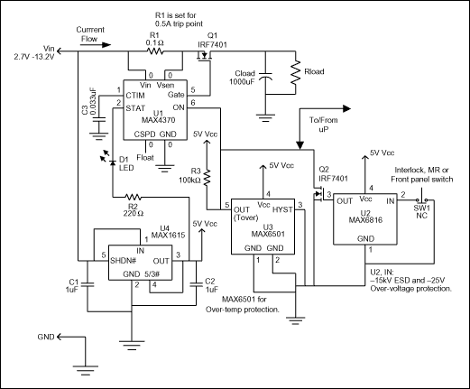
Figure 1 is a flexible circuit that limits current or removes power in response to a command from the user or other fault-indicating signal. It accommodates manual-reset (MR), over-temperature, and interlock-switch inputs. U1, for instance, is a circuit-breaker IC designed to offer protection in hot-swap applications. Residing on either the backplane/host side or the removable-card/remote-device side of the backplane connectors, it guards against start-up faults when a card or board is inserted into a rack or host with the main power supply turned on.

Figure 1. This circuit provides general over-current and over-temperature protection.
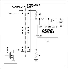
Two main fault conditions are possible. Discharged filter capacitors on the card or remote device can provide a low impedance to ground that momentarily collapses the host power supply. Or, a card only partially seated in its connector can generate erroneous data. U1 prevents the first condition by regulating inrush current during a programmable start-up period, allowing the system to stabilize safely. During normal operation, two internal comparators provide short-circuit and over-current protection (DualSpeed/BiLevel capability). The second condition is handled by routing U1's current output (ON) through two pins at the outer edges of the card (Figure 2).

Figure 2a.

Figure 2b.
Figure 2a and 2b. To insure properly seated pc cards on the backplane's card side (a) or host side (b), this IC (MAX4370) routes current through the outer pins of the card connector.
An internal charge pump generates controlled gate drive for an external n-channel MOSFET power switch (Q1). Following a fault condition, U1 latches Q1 off until cleared by an external-reset signal. To indicate fault conditions, connect an LED (or other fault indicator such as an audible alarm) to U1's open-drain status output (STAT). After a fault is detected, you can reset U1 by pulsing its ON pin low for 20µS minimum.
The switch debouncer (U2) has inputs protected to ±15kV for ESD and to ±25V for circuit faults. Its input (shown connected to a normally-closed pushbutton switch) can clear a fault on U1 or provide a manual reset. An internal pull-up to Vcc eliminates the need for an external pull-up resistor. Replacing the pushbutton switch with an interlock or SPST switch provides a power-disconnect signal, which can implement a chassis-intrusion interlock, or allow a technician to power-down the unit before swapping circuit cards. Because U2's push-pull output cannot be directly OR-connected with other signals connected to U1's ON pin, Q2 is added to create an OR-able open-drain connection.
A temperature switch (U3) adds thermal protection, and its open-drain output can be connected either directly (wire-OR'd) to other signals on U1's ON pin, or separately, back to the microprocessor. With its TO220 package option, U3 can be bolted to a heat sink, or surface-mounted (SOT23 option) close to known heat-generating sources such as R1, Q1, or the main load. In this circuit U3 provides circuit protection by issuing a power-disconnect signal when the circuit temperature becomes critical. A low-power linear regulator (U4) provides 5V to the low-voltage components U2 and U3, but U4 is not meant to provide system power to the load.
- 相关推荐
- 热点推荐
- Flexible
-
MAX33011E-MAX33015E: +5V, 5Mbps CAN Transceiver with ±65V Fault Protection, Fault Detection and Reporting, ±25V CMR, and ±40kV ESD Protectio2023-10-17 27
-
ADG7421F: Low Voltage Fault Protection and Detection, 20 Ω Ron, Dual SPST Switch Data Sheet ADG7421F: Low Voltage Fault Protection and Detec2023-10-16 66
-
MAX33076E: High-Speed Quad RS-422/RS-485 Receivers with ±65V Fault Protection, ±25V CMR, and ±25kV ESD Protection Data Sheet MAX33076E: Hi2023-10-13 42
-
使用STM32 HRTIM的Fault事件做输出保护2023-09-09 5159
-
UG-1887: Evaluating the ADG5421F ±60 V Fault Protection and Detection, 11 Ω RON, Dual SPST Switch2021-01-29 585
-
POWR-GARD Protection Relays an2010-08-26 877
-
Comprehensive Fault Protection2009-09-30 758
-
Add Fault Protection to 4-20mA2009-04-24 1469
-
Fault Protection Saves Multipl2009-04-20 2435
全部0条评论

快来发表一下你的评论吧 !

