
Selectable-Range Current Loop
电源设计应用
454人已加入
描述
Abstract: This article shows an example of implementing a 4-20mA or 0-20mA current-loop output using a voltage output digital-to-analog converter (DAC) and a V to I converter.
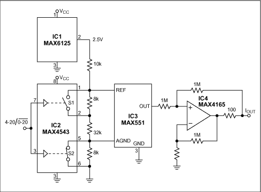
Current-loop signals, as opposed to voltage signals, are commonly used in industrial systems because they are much less subject to noise and relatively indifferent to line length (because the current is unaffected by line resistance). The circuit of Figure 1 allows digital selection between the two standard ranges of current-loop transmission common in industrial systems (0-20mA and 4-20mA).

Figure 1. This circuit's single control input selects a current-loop range of 0-20mA or 4-20mA.
The analog switch (IC2) controls a resistive divider driven by the 2.5V reference (IC1), such that the AGND offset is either 0V or 0.4V, and the DAC's Δ voltage (OUT minus AGND) is either 2V or 1.6V. Thus,
for 0mA to 20mA, Δ = 2V and AGND = 0V;
for 4mA to 20mA, Δ = 1.6V and AGND = 0.4V.
The voltage-output D/A converter (IC3) drives a V/I converter (op amp IC4 and associated resistors) to produce the current loop. Because the DAC's output resistance in voltage mode is high (11kΩ), the resistor values are are made large to preserve accuracy. The op amp's output-drive capability is 80mA. To maintain good linearity, the reference voltage at OUT (IC3 pin 1) should not exceed 2V.
A similar version of this article appeared in the October 15, 2001 issue of EE Times magazine.
打开APP阅读更多精彩内容
Current-loop signals, as opposed to voltage signals, are commonly used in industrial systems because they are much less subject to noise and relatively indifferent to line length (because the current is unaffected by line resistance). The circuit of Figure 1 allows digital selection between the two standard ranges of current-loop transmission common in industrial systems (0-20mA and 4-20mA).

Figure 1. This circuit's single control input selects a current-loop range of 0-20mA or 4-20mA.
The analog switch (IC2) controls a resistive divider driven by the 2.5V reference (IC1), such that the AGND offset is either 0V or 0.4V, and the DAC's Δ voltage (OUT minus AGND) is either 2V or 1.6V. Thus,
for 0mA to 20mA, Δ = 2V and AGND = 0V;
for 4mA to 20mA, Δ = 1.6V and AGND = 0.4V.
The voltage-output D/A converter (IC3) drives a V/I converter (op amp IC4 and associated resistors) to produce the current loop. Because the DAC's output resistance in voltage mode is high (11kΩ), the resistor values are are made large to preserve accuracy. The op amp's output-drive capability is 80mA. To maintain good linearity, the reference voltage at OUT (IC3 pin 1) should not exceed 2V.
A similar version of this article appeared in the October 15, 2001 issue of EE Times magazine.
声明:本文内容及配图由入驻作者撰写或者入驻合作网站授权转载。文章观点仅代表作者本人,不代表电子发烧友网立场。文章及其配图仅供工程师学习之用,如有内容侵权或者其他违规问题,请联系本站处理。
举报投诉
-
MAX40213: Transimpedance Amplifiers with Selectable Gain and Input Current Clamp Data Sheet MAX40213: Transimpedance Amplifiers with Selecta2023-10-16 44
-
Gowin FOC Current Loop Control IP用户指南2022-10-09 613
-
Gowin FOC Current Loop Control Light IP的用户指南2022-10-08 599
-
Gowin FOC Current Loop Control Light IP用户使用指南2022-09-30 581
-
Gowin FOC Current Loop Control用户指南2022-09-15 559
-
LTC2063 Demo Circuit - Low Power 4-20mA Current Loop Sense Amplifier2021-02-03 870
-
XTR117,pdf(4-20mA Current-Loop2010-09-26 2657
-
Ultraprecise Current Sense Amp2009-09-23 736
-
可选范围电流环-Selectable-Range Curre2009-05-07 1162
-
Current-Sense Amplifiers Provi2008-10-01 1199
-
BUF634 pdf datasheet(high speed unity-gain open-loop buffer)2008-08-06 2098
全部0条评论

快来发表一下你的评论吧 !

