
The MAX1463EVKIT Setup and Fun
MEMS/传感技术
1325人已加入
描述
Abstract: The MAX1463 is a highly integrated, low power, two-channel sensor signal processor optimized for industrial and process control applications such as pressure sensing, RTD and thermal-couple linearization, weight sensing, and remote process monitoring with limit indication. The MAX1463 accommodates sensors with outputs ranging from 1mV/V to 1V/V. It includes two 16-bit output DACs, two 12-bit PWM outputs, and supports 4mA–20mA output. It incorporates a 16-bit CPU, 4Kb of program and 128 bytes of user flash memory.
The following procedure will guide you to set up the MAX1463 hardware/software and verify that it is functioning correctly.
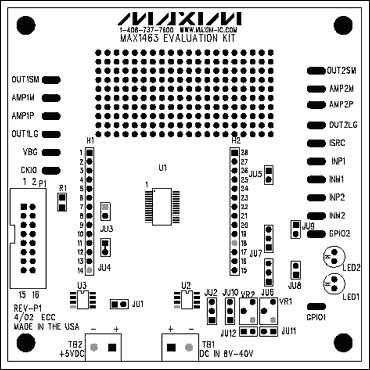
Figure 1. The MAX1463 evaluation board.

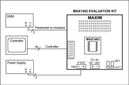
Figure 2. Hardware connection.


打开APP阅读更多精彩内容
The following procedure will guide you to set up the MAX1463 hardware/software and verify that it is functioning correctly.
Hardware Requirements
- Microsoft® Windows 98 or higher.
- 32MB of RAM.
- 20MB of hard disk.
- One parallel port.
EV board Configuration
- See the MAX1463 evaluation board diagram in Figure 1.
- Configure the EV board jumpers per Table 1

Figure 1. The MAX1463 evaluation board.
Table 1. EV Board Jumpers Configuration
|
|
SHORT | Power Supply Selection | Unregulated external +8VDC to +40VDC. |
|
|
SHORT Pin 1-2 |
VREF Selection |
Internal VREF. Pin-1 is at the bottom. |
|
|
OPEN | Clock Selection | Internal Oscillator |
|
|
SHORT (shorted) |
Communication Interface |
3-Wire Communication Interface. Cut wire to open. |
|
|
OPEN | ISRC pin Configuration | ISRC pin floating. |
|
|
OPEN | GPIO1 Mode | Logic level = 0 |
|
|
OPEN | GPIO2 Mode | Logic level = 0 |
|
|
SHORT | LED1 Configuration | LED1 driven by GPIO1. |
|
|
SHORT | LED2 Configuration | LED2 driven by GPIO2. |
|
|
OPEN | Bridge Voltage Drive Selection |
Bridge Voltage connected to +5VDUT. Pin 1 is at the bottom. |
|
|
OPEN | INP1 Configuration | INP1 floats. |
|
|
OPEN | INM1 Configuration | INM1 floats. |
Hardware Connection
- Set up the system per Figure 2.
- Connect the DMM. The terminals are connected between the VSS (pin 14) and any pin you wish to measure. For example: small op-amp; large op-amp; Channel-1... etc.
- Connect one end of the 16-pin ribbon cable between the 16-pin headers on the EV board and the communication KEY. Please make sure the pin-1 of the ribbon cable is connected to the pin-1 of the boards.
- Apply 9V supply to the TB1 terminal block.
- Connect the 25-pin connector of the KEY to the computer parallel port. Any available parallel port is acceptable.

Figure 2. Hardware connection.
Software Installation
- Insert the MAX1463 CD in the CD drive.
- Install ASM1463 in your computer. The default destination directory is "C:MAX1463". The destination directory can be changed as desired.
- The MAX1463 control software and supporting files will be stored in the specified directory.
System Verification
-
Run the "Hardware Debugger":
"Start/Programs/Maxim MAX1463 Evaluation Kit/Hardware Debugger"

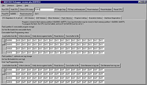
- Press function-key F9 or select the "Flash Memory" tab.

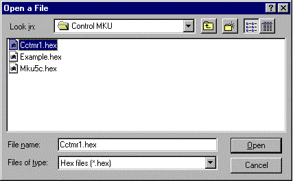
- From "Flash Position 0" block of the window, press the "Load buffer from file" button. An open file window will appear that will include the following files. Select the "Ccmtr1.hex" and press Open.

- From "Flash Position 0" block of the window, press the "Write to device" button. At completion, "Programming complete" statement will be displayed.

- From "Flash Position 0" of the window, press the "Verify device against buffer". The program will read the content of the flash memory (what you just wrote) and compare that with the buffer (what you intended to write). At completion, "Verify complete" will be displayed. In case of failure, a "mismatch..." message will be displayed along with the address of the memory location where the mismatch was found.
- Press "Reset CPU"
-
Press "Run CPU".
The red LEDs on the EV board will start flashing.
The blinking LEDs confirm that the software installation was successful, you have proper hardware setup, and the EVKIT is working. -
Press "Halt CPU".
The LEDs will stop blinking.
View Program Listing
- Select the "Program Listing" tab

-
From the directory you installed the MAX1463 programs, Open the "Cctmr1.lst" listing with File | Open...

-
You may roll the side bar up and down in order to view the entire program listing.
Microsoft is a registered trademark of Microsoft Corp.
声明:本文内容及配图由入驻作者撰写或者入驻合作网站授权转载。文章观点仅代表作者本人,不代表电子发烧友网立场。文章及其配图仅供工程师学习之用,如有内容侵权或者其他违规问题,请联系本站处理。
举报投诉
-
MAX19692EVKIT-MAX19693EVKIT: Evaluation Kit for the MAX19692/MAX19693 Data Sheet MAX19692EVKIT-MAX19693EVKIT: Evaluation Kit for the MAX19692023-10-17 49
-
MAX20408EVKIT-MAX20410EVKIT: Evaluation Kit for the MAX20408/MAX20410 Data Sheet MAX20408EVKIT-MAX20410EVKIT: Evaluation Kit for the MAX20402023-10-16 71
-
MAX25262EVKIT-MAX25263EVKIT: Evaluation Kit for the MAX25262/MAX25263 Data Sheet MAX25262EVKIT-MAX25263EVKIT: Evaluation Kit for the MAX25262023-10-13 61
-
MAX77348EVKIT:MAX77348EVKIT 评价工具包数据表 ADI2023-10-10 37
-
MAX20446EVKIT# MaximIntegratedMAX20446EVKIT评估套件2020-11-11 703
-
MAX20030EVKIT# MaximIntegratedMAX20030EVKIT评估套件2020-11-03 197
-
MAX20090EVKIT# MaximIntegratedMAX20090EVKIT评估套件2020-10-30 293
-
MAX2640EVKIT-MAX2641EVKIT2016-12-16 618
-
MAX1463传感器的补偿算法-The MAX1463 Se2009-05-06 765
-
The MAX1463 Sensor Compensatio2009-04-20 1297
-
MAX5863EVKIT-MAX5865EVKIT评估板中文2008-05-05 1024
-
MAX19710EVCMODU-MAX19713EVKIT评2008-04-23 815
全部0条评论

快来发表一下你的评论吧 !

