

New ICs Revolutionize The Sens
通信设计应用
描述
The MAX1457 is a low-cost/high-performance signal conditioner that in addition to temperature correction, it linearizes a sensor output by establishing 120 piecewise-linear segments, drawing on data stored in EEPROM. The resulting linearized output is accurate to within 0.1% of the sensor's repeatable error. Although this application note concentrates on the MAX1457 smart signal conditioner, the concept presented here applies to all analog signal conditioners developed by Maxim.
Maxim Integrated Products has introduced several ICs that are revolutionizing the interface to low-level bridge sensors in modern industrial systems. All of these ICs provide sophisticated sensor compensation and temperature correction. The high-end device (MAX1457) linearizes a sensor output by establishing 120 piecewise-linear segments, drawing on data stored in EEPROM. The resulting linearized output is accurate to within 0.1% of the sensor's repeatable error.
Though originally developed for use in piezoresistive pressure-sensor applications, these flexible signal-conditioning ICs are equally suited for use with accelerometers, strain gauges, and other low-level bridge-type sensors. They can be used in an industrial sensor, in a 4–20mA or 0 to 5V transmitter, or in a complete instrument. Self-calibration enables these ICs to derive high accuracy from less than ideal sensors—without the need for complex front-end analog circuitry or (in the case of the MAX1457) firmware-based linearizers or multi-order polynomials. Because the IC design is based on analog cells, the devices are easily customized for use with other sensor types (capacitive, inductive, etc.).
All of these ICs provide a signal path that includes flexible sensor-excitation circuitry, a programmable-gain amplifier (PGA), and an analog output. The basic device (MAX1450) includes only those functions. The midrange part (MAX1458) calibrates the gain, offset, and temperature drift of these parameters by adding four 12-bit digital-to-analog converters (DACs); one coarse 3-bit DAC; and a nonvolatile, internal EEPROM for storing the DACs' calibration data. The high-end device (MAX1457) contains six 16-bit DACs and one 12-bit analog-to-digital converter (ADC), and operates with a larger, external EEPROM.
Product Descriptions
MAX14xx ICs offer different levels of integration and accuracy. The MAX1458, for example, is a high-integration, mixed-signal, compensating front-end device that includes EEPROM calibration memory, analog signal path, four 12-bit DACs for controlling offset and gain, and one coarse-offset 3-bit DAC (Figure 1). Its analog output can be scaled from 0.5V to 4.5V for transducer applications or can feed directly to a system ADC for instrument applications.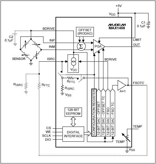
Figure 1. The MAX1458 sensor-interface IC in its ratiometric configuration.
Driven by the temperature and linearity errors of a piezoresistive transducer (PRT), the MAX1458 provides an accuracy of approximately 1%. Its high level of integration provides hands-off calibration without potentiometers. Because it makes corrections in the analog domain, the MAX1458 can also simplify the architecture of analog-output sensors and transmitters. Unlike systems that digitize the raw sensor output, make corrections in microprocessor firmware, and produce the analog output with a DAC, the MAX1458 achieves low cost, low noise, and simple operation with a signal path that is fully analog.
By adjusting the sensor's bridge-excitation current, two 12-bit DACs within the MAX1458 implement fine control of the sensor's gain and temperature coefficient (tempco) of gain. The internal, fully differential PGA/IA (instrumentation amplifier) front end has 90dB of common-mode rejection and digitally controllable gain in the +45V/V to +220V/V range. To achieve control of the sensor offset and the temperature compensation of offset, the signal following the PGA is summed with the outputs of two more 12-bit DACs. An on-board 128-bit EEPROM contains the input data for each DAC, plus a configuration register and 24 bits of "user area" for general use. The IC also includes a high-tempco resistor that is useful as a temperature sensor when compensating certain types of transducers.
The MAX1457 (Figure 2) is a high-accuracy, mixed-signal, linearizedfront-end device. Unlike the MAX1458, it includes a 12-bit ADC that digitizes the raw sensor temperature and develops addresses for an external linearization EEPROM. A 120-segment curve stored in this EEPROM applies the offset and gain corrections that linearize and temperature-correct the MAX1457 output.
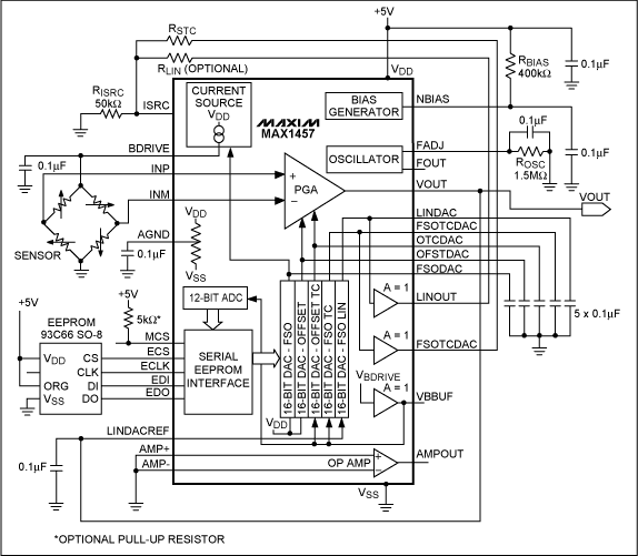
Figure 2.The MAX1457 sensor-linearizer IC in its ratiometric configuration.
Though it lacks an internal EEPROM, the MAX1457 directly addresses standard MICROWIRE™EEEPROMs such as the 93C66 from National Semiconductor Corp. Its analog signal path includes an uncommitted op amp, five 16-bit gain- and offset-controlling DACs, and a 12-bit ADC. In general, the MAX1457 sacrifices low cost and small size in favor of higher absolute accuracy and better linearity. Though larger than the MAX1458, the MAX1457 employs analog-domain corrections that provide an architecture simpler than that of most analog output sensors. The analog output can be scaled to produce a 4–20mA signal, or it can feed directly to a system ADC. With PRT pressure sensors, the MAX1457 can achieve a typical corrected accuracy of 0.1%.
Figure 3 illustrates the MAX1457's ability to compensate for temperature and linearity errors. Graph 3a shows the low-level output of an uncompensated piezoresistive sensor with its huge temperature errors of offset and gain (3b). Graphs 3c and 3d show the signal after conditioning. The MAX1457 scales the sensor output in the 0.5V to 4.5V range (3c), and limits gain and offset errors to 0.1% over a wide temperature range (3d).
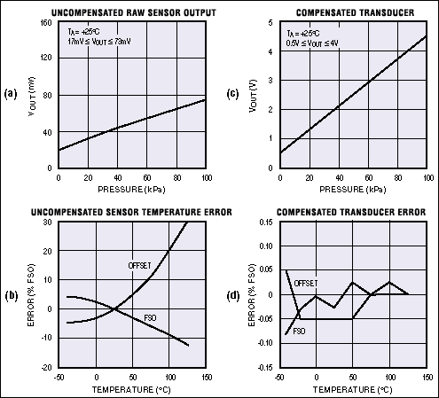
Figure 3.Raw output from a sensor (a) is amplified and conditioned by the MAX1457 (b), and the sensor's temperature errors (c) are compensated by the MAX1457 as well (d).
The MAX1450 is a stripped-down version of the MAX1457/MAX1458, containing only the analog front end of those devices without their DACs, ADCs, or EEPROMs. It offers a controllable sensor-excitation source and a PGA with very flexible calibration and offset features. As a flexible PGA and current source, it offers capabilities not found in standard IAs and PGAs: orthogonal and easily managed inputs for the correction of gain, offset, and other parameters. The coarse PGA gain is controlled digitally, and the offset and excitation current source (gain) are controlled by externally applied analog signals.
Background
Traditional transducers calibrate and compensate the sensor in the analog domain using "analog memory" components such as potentiometers, capacitors, and laser-trimmed thin-film resistors. Such transducers sometimes employ thermistors, diodes, or other analog techniques for temperature compensation. Though unwieldy, diode breakpoints are sometimes used to enhance linearity. All these approaches have major disadvantages:- Compensation accuracy is restricted by nonlinear sensor errors
- Compensation devices are afflicted by temperature drift
- Laser trimmers and other automatic equipment are expensive
- Manual calibration ("pot tweaking") translates to higher cost.
Digital-Sensor Signal Processors (DSSP): DSSP techniques include conversion of sensor signals to the digital domain with an ADC, calibration and compensation in the digital domain using a microcontroller with EEPROM, and the use of a DAC (if required) to convert the compensated result back to an analog signal. The advantage of this approach occurs after digitization by the ADC, when further signal processing occurs in the processor's zero-drift digital domain. Disadvantages include software complexity, memory requirements, and a reduced dynamic range that calls for higher resolution in the ADC. Most of these problems will be solved by the DSSP architecture in the new MAX1460.
Analog-Sensor Signal Processors (ASSP): By adjusting the sensor excitation and digitally adjusting the amplifier offset and gain, ASSP techniques achieve sensor calibration and temperature compensation in the analog domain without quantizing the signal. Through the use of DACs, EEPROMs, and digitally adjustable analog electronics, this hybrid technique offers the best of the all-analog and all-digital approaches—signal processing in the analog domain with the "potless" ease of a digital system.
To linearize the sensor, ASSP systems adjust gain and offset using feedback from the raw sensor output to the DAC reference inputs. This powerful ASSP technique (used in MAX14xx devices) eliminates the unwieldy polynomial curve fitting required in DSSP approaches. The DAC, which multiplies a digital number by an analog voltage (the DAC's reference input), is the key element in an ASSP electronic trimming system.
High-resolution DACs are expensive, however, and a sensor requires several of them for proper ASSP compensation. This problem has been resolved by the development of a new sigma-delta technology for DACs and ADCs (MAX14xx series) that enables low-cost digital trimming. It yields 16-bit converters on very small areas of silicon, which in turn allows complex systems-on-a-chip that include multiple DACs and ADCs.
Test and Calibration Issues
An important consideration in the design of the sensor signal-conditioner architecture was the need to support advanced manufacturing technologies. To meet that requirement, the IC designers lowered manufacturing costs by integrating (along with signal-conditioning functions) the following three traditional sensor-manufacturing operations into one automated process:Pretest: This operation tests sensor performance over the compensated temperature and pressure ranges. The ICs' MICROWIRE interface and three-state outputs enable control by a host test computer. These capabilities enable testing of multiple transducers in a parallel connection (Figure 4), and allow digital communication between the test system and any specific transducer (selected through a chip-select pin).
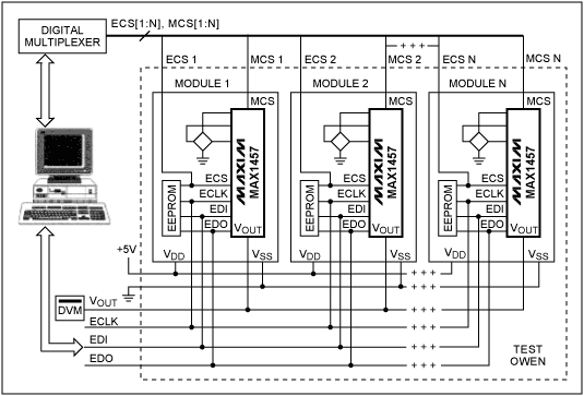
Figure 4. In this automated calibration system, the MICROWIRE interface simplifies the calibration of multiple sensors. The signal-conditioning ICs can be MAX1457s or MAX1458s.
Calibration and Compensation: This operation can be performed immediately after pretest, without removing the transducers from their test sockets. The test computer simply calculates the calibration and compensation coefficients (4kbits) and downloads them through the MICROWIRE interface to the transducer's EEPROM.
Final Test: This operation verifies transducer performance, again without removing the device from its test socket.
MAX1457/MAX1458 Compensation Scheme
Two compensation methods are implemented by the MAX1457. The first is analog, in which two DACs compensate the 1st-order temperature errors: an offset-TC DAC adjusts the output offset, and an FSO-TC DAC adjusts the bridge-excitation voltage by adjusting its excitation current (Figure 5). The less expensive MAX1458 makes these corrections and no others.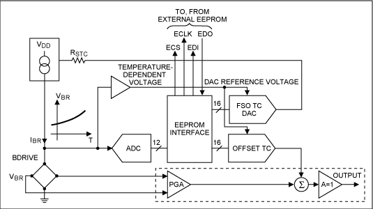
Figure 5. Simplified circuitry within the MAX1457 illustrates the correction of temperature errors. Analog voltage across the sensor bridge generates the DAC reference voltages, which in turn produce the 1st-order analog corrections. The bridge voltage is also digitized to provide fine correction through the EEPROM look-up table.
The second method of compensation is digital. An ADC driven by the bridge-excitation voltage (a temperature signal) generates the EEPROM address. The EEPROM output is a multiple-segment approximation (up to 120 segments) that corrects residual higher-order errors. MAX1457-based compensation employs 16-bit DACs to provide all of the functions listed in Table 1. The MAX1458 employs four 12-bit DACs and a 3-bit offset DAC to provide only those functions marked with asterisks.
Table 1.Digital Compensation DAC Functions
| Function | DAC Type |
| Initial offset calibration* | Offset |
| Initial FSO calibration* | FSO |
| Correction of TC slope for analog offset | Offset TC |
| Correction of TC slope for nonlinear offset | Offset TC |
| Correction of TC slope for analog FSO* | FSO TC |
| Correction of TC nonlinearity for nonlinear FSO* | FSO TC |
| Correction of pressure nonlinearity | FSO linearity |
Initial offset is corrected by feeding to the PGA's summing junction a voltage obtained by multiplying (within the offset DAC) a fraction of the supply voltage by a 16-bit word. The full-span output (FSO, or gain) is calibrated in two adjustments: coarse gain is set by feeding a 3-bit digital word to the PGA, and fine gain is set by adjusting the bridge current using another 16-bit word.
Two DACs connected to the bridge voltage (the offset-TC DAC and FSO TC DAC) compensate linear components of the zero and FSO TC. Bridge voltage is proportional to temperature, and a properly valued digital word (the multiplier coefficient) causes the DAC output to compensate the temperature slope by following the quasilinear change in bridge voltage.
MAX1457 Multislope Compensation Scheme
Digital multislope temperature compensation allows compensation of arbitrary error curves, whose shape is determined only by the shape of the temperature signal and the adjustment range available in the electronics. This compensation is implemented with 120 number pairs (corrections for offset TC and FSO TC) stored in EEPROM look-up tables. The EEPROM address is the output word of a 12-bit ADC driven by the bridge voltage, which (with constant current excitation of the bridge) is temperature dependent. See Figure 5.Pressure nonlinearity is corrected by feedback from the output voltage to the bridge current source. To gain control of this feedback, the output voltage is routed to the reference input of a DAC, whose output connects to the current source and is then subject to the DAC's digital input, driven by a coefficient stored in the EEPROM (Figure 6). Thus, coefficients delivered to the DAC can introduce a nonlinearity in the bridge current that compensates (often by an order of magnitude) for nonlinearity in the sensor output. See the product data sheets for further details on operation.
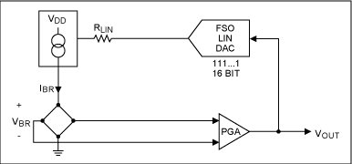
Figure 6. This simplified circuit, also internal to the MAX1457, demonstrates the concept of pressure-nonlinearity correction.
Application Example
Although the MAX1457 was designed as an ASIC, primarily for voltage-output configurations, it also includes support for the popular fixed-output, 4–20mA, 2-wire transducers. An on-chip, uncommitted op amp lets you create the 2-wire current loop. As shown in Figure 7, this amplifier and an external resistor form a program-mable current source. Loop current is set by resistor RA and controlled by feedback via RC. A voltage regulator (REF02) accepts the 4–20mA current-loop voltage (typically 20V to 40V), and provides a stable 5V reference for the MAX1457. Thus, the REF02 increases the circuit's operating voltage while providing independence from changes in the supply voltage.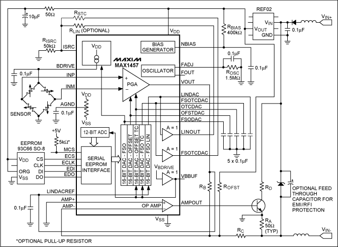
Figure 7. Four milliamps power the transducer in this 4-20mA, 2-wire circuit based on the MAX1457. Pressure is proportional to a 0-16mA current transmitted over the same pair of wires.
A diode in series with the positive power-supply terminal protects against reverse-polarity connections in the field, and another specialized diode (TransZorb™) connected across the power terminals protects against voltage spikes. The optional resistor RD reduces power dissipation in the output transistor.
MICROWIRE is a trademark of National Semiconductor Corp.
TransZorb is a registered trademark of Vishay Intertechnology, Inc.
- 相关推荐
- 热点推荐
- Interface
-
DLPA2000的PWM_IN,CMP_OUT,SENS1,SENS2不用如何处理呢?2025-02-27 416
-
C++内存管理operator new和placement new2023-07-22 1413
-
New Imaging Technologies传感器的特性2021-12-02 702
-
ICS是什么?ICS直放站有什么应用?2021-05-27 2974
-
时钟芯片ICS950208相关资料分享2021-03-31 903
-
时钟芯片ICS950908资料推荐2021-03-30 932
-
时钟芯片ICS950227资料推荐2021-03-25 1683
-
EV_ICS-51360-FX TDK InvenSense ICS多模MEMS麦克风2020-11-11 632
-
Sigfox为尚未建置IoT网络客户 推Sens'It Discovery监控服务2018-05-31 1231
-
placement new详解2018-03-02 537
-
New ICs Revolutionize The Sensor Interface2017-04-10 636
-
各位大神能不能告诉我ICS844021AGI-01 和 ICS844021BGI-01有什么区2012-03-10 2676
-
New RS-232 ICs Feature 1µ2009-04-22 945
-
Analog ICs for Low Voltage Sys2008-09-11 1972
全部0条评论

快来发表一下你的评论吧 !

