
使用DS32x35的8051型微控制器-Using a DS
嵌入式新闻
描述
Overview of the DS32x35
The DS32x35 real-time clock (RTC) is a temperature-compensated clock/calendar that includes an integrated 32.768kHz crystal, an I²C interface, and a bank of nonvolatile memory in a single package. The DS32x35's integration of a crystal resonator enhances the long-term accuracy of the device and reduces the piece-part count in a manufacturing line.The RTC provides seconds, minutes, hours, day, date, month, and year information. The date at the end of the month is automatically adjusted for months with fewer than 31 days, including corrections for leap year. The clock operates in either the 24-hour or 12-hour format with an AM/PM indicator. Additionally, the clock provides two programmable time-of-day alarms and a programmable square-wave output.
Interfacing the DS32x35 to a µC
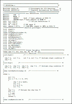
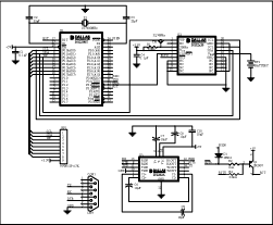
This application note demonstrates how to interface the DS32x35 to an 8051-type microcontroller, such as the DS2250 soft-microcontroller module. Additionally, Figure 1 provides example code, written in C, for implementing basic interface routines, including routines for reading the time and date from the real-time clock (RTC); writing time and date data to the RTC from user entries; writing and reading data to and from the FRAM; reading the temperature from the temperature sensor; and selecting the proper FRAM density. The software supports both FRAM densities: 16kb (DS32B35) and 64kb (DS32C35).Figure 2 is a schematic that illustrates the connections required for interfacing the DS32x35 RTC with an 8051-type microcontroller. The program uses two general-purpose (GP) port pins on the microcontroller to communicate with the DS32x35 using an I²C serial interface; a third GP port pin is used to enable or disable the write-protect (WP) input pin for the FRAM. The microcontroller's internal UART drives two port pins, which are connected to a DS232 line driver/receiver. User inputs and data outputs from the program are passed through the RS-232 interface from a PC's terminal-emulator program to the microcontroller. The RS-232 DTR input line controls the microcontroller's reset input.

Download (TXT, 11.5kB)
Figure 1. Program Listing

More detailed image (PDF, 260kB)
Figure 2. A schematic illustrating the connections for interfacing the DS32x35 with an 8051-type microcontroller.
- 相关推荐
- 热点推荐
- ds3
-
DS1307与兼容8051的微控制器接口2023-03-01 2307
-
DS1302与8051型微控制器接口2023-01-09 1342
-
高速安全微控制器DS5250电子资料2021-04-21 1227
-
DS1318与8051微控制器的接口2018-12-18 1385
-
DS80C310 高速微控制器2009-09-19 939
-
DS5250中文资料 (高速安全微控制器)2009-05-11 1047
-
DS1302 RTC与8051微控制器的接口2009-04-21 2480
-
DS32X35带有铁电随机存取存储器的高精度实时时钟(RTC2009-04-17 887
全部0条评论

快来发表一下你的评论吧 !

