

简单的演示如何使用一个DS1232和MicroMonitor
通信设计应用
66人已加入
描述
Abstract: Discusses how the DS1232 can be used to MicroMonitor an 8051-based system. This supervisor circuit provides power-on-reset (POR), manual reset (push-button) input, a watchdog timer (strobe timer), and an early power-fail comparator. The reset threshold tolerance can set selected to monitor both 5% and 10% supply tolerance systems. In addition, a pin-selectable reset time-out delay is available.
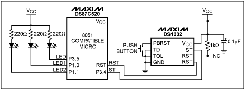
Figure 1. An 8051 Compatible circuit using the DS1232 as a reset controller.
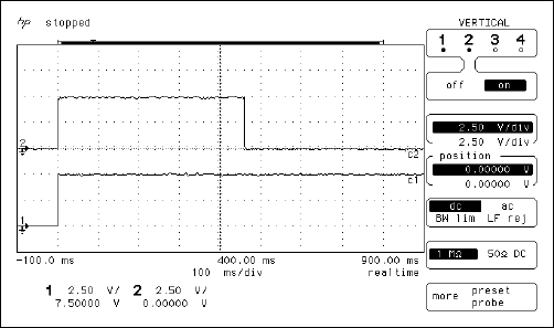
Figure 2. Typical RST signal during power-up sequence: 1) VCC 2) RST.
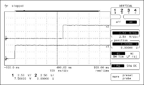
Figure 3. Typical active-low RST signal during power-up sequence: 1) VCC 2) active-low RST.
After the reset signal becomes inactive, the microcontroller must strobe the ST signal low before the watchdog timer elapses. The DS1232's watchdog timer cannot be disabled, so this must occur within n ms of the reset signals becoming inactive, or the microprocessor will be reset. The watchdog time-out values for the DS1232 are programmable and specified with somewhat wide ranges. However, it is best to strobe the ST pin faster than the minimum watchdog time-out specification, because it eliminates the chance that a fast watchdog will cause the system to erroneously reset. The watchdog time-out can be set to one of three values by adjusting the value of the TD pin according to Table 1.
Table 1. Watchdog Time-Out Values for Each TD Pin State
Figure 1 shows the TD pin grounded, and hence ST must see a negative edge every 62.5ms to guarantee that the microprocessor will not be reset. If it is strobed at the typical rate of 150 ms, there is a chance that it would work with one MicroMonitor but not another. The inclusion of the minimum, typical and maximum values informs the end user of the behavior of the watchdog. Program the TD such that the microprocessor can strobe the ST pin before it reaches the minimum time-out and plan on it taking as long as the maximum time-out to reset the microcontroller. The typical value does not apply to any specific MicroMonitor; it simply shows that the critical time is between the minimum and maximum time-out value. Thus, the typical value for any given MicroMonitor could range anywhere between the minimum and maximum time-out values.
Figure 4 (below) shows the strobe signal that was used for the same hardware setup. Trace # 1 shows VCC and #2 shows ST. As the same hardware was used with the reset signals shown in Figures 2 and 3, the reset was de-asserted at ~460ms. The first negative edge of the strobe signal occurs at 496 ms, or 36 ms after reset becomes inactive. This is sufficiently early to guarantee that the watchdog will not reset the system unless the microcontroller enters an unanticipated state.
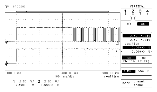
Figure 4. Watchdog strobe signal (ST) at the beginning of execution: 1)VCC 2) ST.
As you can see from Figure 5 (below), the ST signal receives a negative-edge approximately every 20 ms. With a faster microprocessor, there is no reason not to strobe more often than required. Also, on this graph it is easy to see that the strobes start to occur at 496 ms after the voltage is applied.
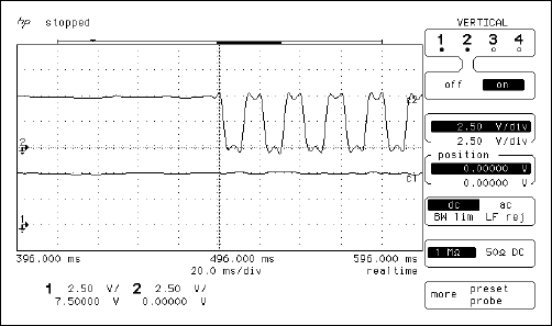
Figure 5. Zoom showing frequence of the ST signal: 1)VCC 2) ST.
The DS1232 will also debounce a momentary switch without additional hardware, making it easy to add a pushbutton reset to over-ride the system. The pushbutton is shown in Figure 1, and the RST and active-low RST signals it causes are shown in Figures 6 and 7. Note that the pushbutton does not bounce when connected to the DS1232 and that the reset is held for approximately the same period of time as a reset during power-up (610 ms typically). Also note that a pull-up resistor is not required for the pushbutton, because an internal pull-up resistor is available within the DS1232.
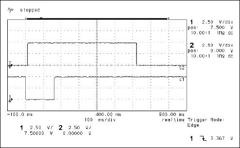
Figure 6. Pushbutton causing reset without bouncing: 1) active-low PBRST 2) RST.
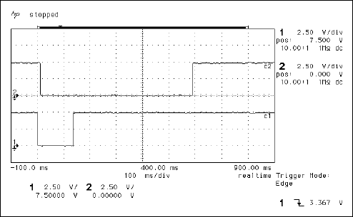
Figure 7. Pushbutton causing reset without bouncing: 1) active-low PBRST 2) active-low RST.
The DS1232 also contains a power failure monitor. The DS1232 monitors VCC at all times and resets the microcontroller if the voltage drops below VCCTP (VCC trip point). VCCTP can be programmed to 5% or 10% below VCC, and the MicroMonitor will hold the reset signals active for 250 ms to 1 second after VCC recovers and returns above VCCTP. VCCTP is programmed with the TOL pin. If the TOL pin is grounded, a 5% tolerance is selected; if it is tied to VCC, then a 10% tolerance is selected. This allows designers to select the tolerance that works best for their systems, allowing maximum flexibility of design. The 5% tolerance forces a reset somewhere between 4.50V and 4.74V, and the 10% tolerance forces the reset pins active between 4.25V and 4.49V.
For the reference design shown in Figure 1, the 5% tolerance was chosen. Looking at the oscilloscope plot in figure 8, VCCTP for this specific MicroMonitor can be determined. X2 on the plot is lined up with the edge of RST and the cross point Y2 is at 4.6V.
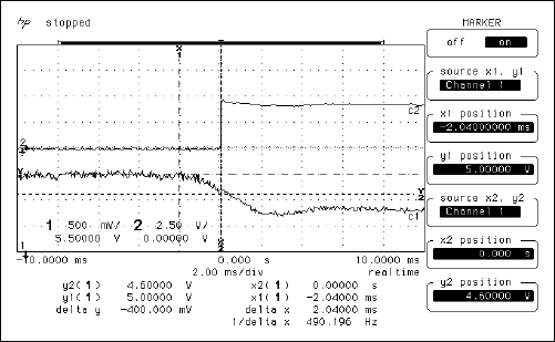
Figure 8. RST Pin behavior when VCC falls below VCCTP: 1) VCC 2) RST.
The skew rate of VCC when falling is ~500mv/ 10 ms or ~50V/s. The DS1232 datasheet specification requires the fall time between 4.75V to 4.25V to be greater than or equal to 300 ms, giving a maximum slew rate of 1.667kV/s. As you can see, this is easily met by this power system.
The next oscilloscope plot shows the power-up sequence as VCC leaves a "brownout" condition. VCC has been static at 4.3V, and it will return to 5.0V. The DS1232 will hold the reset active for the reset active time of 250ms to 1 second after the transition occurs on VCC. In the case below, the MicroMonitor held the reset active for approximately 460 ms.
Figure 9. Voltage recovers from 4.3V "Brownout": 1) VCC 2) RST.
This code is 100% event driven, and hence the main program is simply an infinite loop. The software takes advantage of Maxim's interrupt priority scheme and allows the interrupt hardware to service first the internal power failure interrupt (non- maskable), then the internal watchdog interrupt, and finally the timer 0 interrupt, which is used to strobe the external watchdog on the DS1232. The redundancy provided by using both the internal and external power and code monitoring ensures that these critical functions are performed without error.
Interrupt routines interact as shown in Figure 10 below.
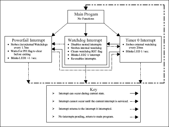
Figure 10. Interrupt interaction / program flow diagram.
Timer 0 is the lowest priority interrupt. Thus, it can be interrupted by either the Watchdog Interrupt (high priority) or the Power-Fail Interrupt (highest priority). If timer 0 is not interrupted, it will toggle the strobe pin (ST) of the DS1232 every 10ms and toggle the heartbeat LED every 50 trips through the ISR (500ms). At the end of its execution, it returns control to the main program.
If the timer ISR (Interrupt Service Routine) is interrupted by the watchdog and/or the power-fail interrupt, then control is immediately transferred to the highest priority pending interrupt. If the watchdog timer elapses, then the watchdog functions (listed on the diagram) are performed to completion, and then control will either be transferred to the Power Fail Interrupt or back to the Timer 0 Interrupt, depending on if a power-fail interrupt was received during the execution of the watchdog functions. If no power-fail interrupt was received, then the timer 0 interrupt will attempt to finish. If the timer 0 ISR is not further bothered by a power-fail interrupt, it will complete and return to the main program. If timer 0 is interrupted by the power-fail interrupt, it will allow the power fail interrupt to occur first.
If the power-fail interrupt does occur, control is transferred to it, and the ISR executes until the voltage level of VCC returns above the DS87C520s early voltage failure warning level. Since this ISR has the highest priority, it cannot be interrupted by the watchdog interrupt or the timer 0 interrupt. This means that the powerfail ISR must strobe both the internal and external watchdogs, or the watchdogs will reset the part when the voltage sags. In reality, this most likely will not occur because the DS1232 is set to a tighter tolerance than the internal voltage monitor on the microcontroller, and hence the DS1232 would reset the microcontroller before the microcontroller's early voltage failure warning level would be reached. Restated another way, the internal voltage monitoring of the DS87C520 will probably never be used and is a redundant function on this system. The interrupt only occurs in the event that the DS1232 fails. Since the DS1232 is a reliable part, you may be waiting a while if you try to test this condition.
When the power-fail interrupt completes, the next highest pending ISR is serviced. Thus, if the watchdog interrupt occurred during the service of the power-fail interrupt, then it would be serviced first. When it completed, the timer 0 ISR would attempt to finish.
Each interrupt strobes a separate LED, indicating which ISR is currently being serviced routinely.
If redundancy is not required for a specific application, the power-fail and watchdog ISRs can be removed. Removing them will also require you to change the vector jump table at the beginning of the program. It is recommended that you place start in the place of all unused vector addresses. The code that initializes and enables the power-fail and the watchdog interrupts in the MainInit routine also needs to be removed. This will leave you with only the timer 0 ISR, the reset detect routine, an empty main program, and the supporting functions for the serial port. A good start for any 8051 application!
打开APP阅读更多精彩内容
To simplify the use of the device, a software execution program is included to show how the 8051 processor can be used in conjunction with the DS1232.
Introduction
Maxim's DS1232 MicroMonitor chip is a highly integrated solution to add power-on reset delay, a pushbutton reset controller, robust power failure monitoring, and watchdog timer functionality to your microprocessor system with the addition of a single chip. The chip also offers both active and low reset signals, and selectivity of the watchdog time out period and the voltage monitoring level. The high level of integration reduces both the cost of implementation and the board space required. The chips are available in several packages including 8-pin mSOP, SOIC, and DIP.Advantages of Using a Dallas Semiconductor DS1232 MicroMonitor
Power-on Reset Delay Allows Board Resources to Stabilize Before Execution Begins
Precise control of a microcontroller's reset pin is important at all times during the operation of a circuit. Thus, it is imperative that the reset pin is controlled during both normal operation and during the power-up time of the circuit. One common problem with many microprocessor circuits is that the microcontroller begins execution before the memory and I/O resources available to it have a stable power supply. Some chips require hundreds of milliseconds to reset themselves and ready for operation. If a microprocessor begins execution within microseconds of a reset, it could be executing based on invalid input from the system resources. This can be resolved by adding a power-on reset (POR) circuit that holds the microprocessor in reset during the power-up sequence for 100s of milliseconds after a reset occurs. The DS1232 will hold a microcontroller's reset pin active for a minimum time of 250ms (typically 610 ms.) Additionally, it can provide either an active high or active low reset, which makes it compatible with any microprocessor.Pushbutton Reset Circuit Debounces a Momentary Switch and Provides a Solid Reset Pulse
Another common problem in microprocessor circuits is that a less than perfect reset signal causes the microprocessor to reset several times, possibly executing some fragment of the initialization routine several times before the reset finally stabilizes. In some circuits, this is trivial. However, in other circuits this could cause major system problems. The DS1232 has internal circuitry that debounces a pushbutton and provides the system a clean reset signal. This eliminates the need to have both a separate power-on reset circuit and pushbutton circuitry attached separately to the reset pin. Plus, the DS1232 will hold the reset pin low for at least 250 ms to guarantee that the manual reset is received correctly by the microprocessor every time.The DS1232 Provides Power Failure Monitoring
Brownouts and power failures are a reality for most microprocessor systems. Since there is no way to avoid the occasional power cycle, a robust microprocessor solution must account for the various power failure modes. The DS1232 monitors the power supply to a microprocessor and forces the microprocessor into its reset state if there is a brownout or if the power fails altogether. This guarantees that the system will not try to operate during irregular supply voltage conditions, and it can prevent the microprocessor from executing code when it should really be waiting for the supply voltage to return to a valid state.An Internal Watchdog Timer MAY Reset a Microprocessor, but an External Watchdog WILL Reset It
Watchdog timers are used to ensure that if the code operating on a microprocessor enters into an unanticipated state, then the processor will reset after some minimal amount of time elapses. Many microprocessors have an internal watchdog timer that handles this function without an external component. However, the internal watchdog timer can be disabled by the pseudo-random code that is executing on the microprocessor. The external watchdog timer on the DS1232 cannot be disabled. This gives you peace of mind, knowing that if the MicroMonitor is not strobed, then the microcontroller will be reset. Another nice feature of the DS1232 is that the strobe period can be varied to one of three different values. The device thus works well with faster and slower microprocessors because you can program the watchdog timer to an appropriate rate for any microcontroller. Another advantage of the external watchdog timer is that the strobe signal is visible to the external world because it is on an I/O pin. This allows easier debugging of watchdog-related problems.Hardware Required for Using a DS1232 with a Microcontroller
The greatest asset of the DS1232 is that all of the functions listed above are implemented in a single package. This functionality does not require a complex chipset. The schematic below shows how the DS1232 is used with a Dallas Semiconductor DS87C520 Microcontroller. Since most systems incorporate a pushbutton reset, the only things added are the DS1232, a pull-up resistor for the active low output, and a decoupling capacitor to reduce the possibility of noise on the power supply causing a reset. The pull-up resistor is added here because it is used to generate the oscilloscope plots shown on the following pages. The active-low RST output of the DS1232 is not required by the DS87C520. The LEDs on the diagram are used to signal when ISRs (Interrupt Service Requests) are being serviced.Figure 1. An 8051 Compatible circuit using the DS1232 as a reset controller.
Using the DS1232 with a Microcontroller
Once the hardware has been configured, the DS1232 begins controlling the reset signals for power-up, pushbutton reset, power failure reset, and watchdog timer reset. The active high (RST) and active low (active-low RST) power-on resets (POR) are shown in Figures 2 and 3, respectively. The active high reset signal rises with VCC and remains high between 250 ms and 1 second. The active low reset remains 0V until the delay elapses and then is pulled high by the pull-up resistor. The pull-up resistor is required because active-low RST is an open collector output. In the examples below, both RST and active-low RST require about 450 ms to become inactive.Figure 2. Typical RST signal during power-up sequence: 1) VCC 2) RST.
Figure 3. Typical active-low RST signal during power-up sequence: 1) VCC 2) active-low RST.
After the reset signal becomes inactive, the microcontroller must strobe the ST signal low before the watchdog timer elapses. The DS1232's watchdog timer cannot be disabled, so this must occur within n ms of the reset signals becoming inactive, or the microprocessor will be reset. The watchdog time-out values for the DS1232 are programmable and specified with somewhat wide ranges. However, it is best to strobe the ST pin faster than the minimum watchdog time-out specification, because it eliminates the chance that a fast watchdog will cause the system to erroneously reset. The watchdog time-out can be set to one of three values by adjusting the value of the TD pin according to Table 1.
Table 1. Watchdog Time-Out Values for Each TD Pin State
| TD Pin State | Minimum Time-Out | Typical Time-Out | Maximum Time-Out |
| Ground | 62.5 ms | 150 ms | 250 ms |
| Floating | 250 ms | 600 ms | 1000 ms |
| VCC | 500 ms | 1200 ms | 2000 ms |
Figure 1 shows the TD pin grounded, and hence ST must see a negative edge every 62.5ms to guarantee that the microprocessor will not be reset. If it is strobed at the typical rate of 150 ms, there is a chance that it would work with one MicroMonitor but not another. The inclusion of the minimum, typical and maximum values informs the end user of the behavior of the watchdog. Program the TD such that the microprocessor can strobe the ST pin before it reaches the minimum time-out and plan on it taking as long as the maximum time-out to reset the microcontroller. The typical value does not apply to any specific MicroMonitor; it simply shows that the critical time is between the minimum and maximum time-out value. Thus, the typical value for any given MicroMonitor could range anywhere between the minimum and maximum time-out values.
Figure 4 (below) shows the strobe signal that was used for the same hardware setup. Trace # 1 shows VCC and #2 shows ST. As the same hardware was used with the reset signals shown in Figures 2 and 3, the reset was de-asserted at ~460ms. The first negative edge of the strobe signal occurs at 496 ms, or 36 ms after reset becomes inactive. This is sufficiently early to guarantee that the watchdog will not reset the system unless the microcontroller enters an unanticipated state.
Figure 4. Watchdog strobe signal (ST) at the beginning of execution: 1)VCC 2) ST.
As you can see from Figure 5 (below), the ST signal receives a negative-edge approximately every 20 ms. With a faster microprocessor, there is no reason not to strobe more often than required. Also, on this graph it is easy to see that the strobes start to occur at 496 ms after the voltage is applied.
Figure 5. Zoom showing frequence of the ST signal: 1)VCC 2) ST.
The DS1232 will also debounce a momentary switch without additional hardware, making it easy to add a pushbutton reset to over-ride the system. The pushbutton is shown in Figure 1, and the RST and active-low RST signals it causes are shown in Figures 6 and 7. Note that the pushbutton does not bounce when connected to the DS1232 and that the reset is held for approximately the same period of time as a reset during power-up (610 ms typically). Also note that a pull-up resistor is not required for the pushbutton, because an internal pull-up resistor is available within the DS1232.
Figure 6. Pushbutton causing reset without bouncing: 1) active-low PBRST 2) RST.
Figure 7. Pushbutton causing reset without bouncing: 1) active-low PBRST 2) active-low RST.
The DS1232 also contains a power failure monitor. The DS1232 monitors VCC at all times and resets the microcontroller if the voltage drops below VCCTP (VCC trip point). VCCTP can be programmed to 5% or 10% below VCC, and the MicroMonitor will hold the reset signals active for 250 ms to 1 second after VCC recovers and returns above VCCTP. VCCTP is programmed with the TOL pin. If the TOL pin is grounded, a 5% tolerance is selected; if it is tied to VCC, then a 10% tolerance is selected. This allows designers to select the tolerance that works best for their systems, allowing maximum flexibility of design. The 5% tolerance forces a reset somewhere between 4.50V and 4.74V, and the 10% tolerance forces the reset pins active between 4.25V and 4.49V.
For the reference design shown in Figure 1, the 5% tolerance was chosen. Looking at the oscilloscope plot in figure 8, VCCTP for this specific MicroMonitor can be determined. X2 on the plot is lined up with the edge of RST and the cross point Y2 is at 4.6V.
Figure 8. RST Pin behavior when VCC falls below VCCTP: 1) VCC 2) RST.
The skew rate of VCC when falling is ~500mv/ 10 ms or ~50V/s. The DS1232 datasheet specification requires the fall time between 4.75V to 4.25V to be greater than or equal to 300 ms, giving a maximum slew rate of 1.667kV/s. As you can see, this is easily met by this power system.
The next oscilloscope plot shows the power-up sequence as VCC leaves a "brownout" condition. VCC has been static at 4.3V, and it will return to 5.0V. The DS1232 will hold the reset active for the reset active time of 250ms to 1 second after the transition occurs on VCC. In the case below, the MicroMonitor held the reset active for approximately 460 ms.
Figure 9. Voltage recovers from 4.3V "Brownout": 1) VCC 2) RST.
8051 Microcontroller Software for Using a DS1232 MicroMonitor Chip
Software designed to work with the hardware of Figure 1 is provided in Appendix A. The software works with a DS1232 MicroMonitor and a Dallas Semiconductor DS87C520 8051-compatible microcontroller. It provides a robust power and code monitoring system with redundant power and code monitoring. The software can distinguish between when the MicroMonitor resets the controller and when the microcontroller's internal POR or watchdog timer causes the reset.This code is 100% event driven, and hence the main program is simply an infinite loop. The software takes advantage of Maxim's interrupt priority scheme and allows the interrupt hardware to service first the internal power failure interrupt (non- maskable), then the internal watchdog interrupt, and finally the timer 0 interrupt, which is used to strobe the external watchdog on the DS1232. The redundancy provided by using both the internal and external power and code monitoring ensures that these critical functions are performed without error.
Interrupt routines interact as shown in Figure 10 below.
Figure 10. Interrupt interaction / program flow diagram.
Timer 0 is the lowest priority interrupt. Thus, it can be interrupted by either the Watchdog Interrupt (high priority) or the Power-Fail Interrupt (highest priority). If timer 0 is not interrupted, it will toggle the strobe pin (ST) of the DS1232 every 10ms and toggle the heartbeat LED every 50 trips through the ISR (500ms). At the end of its execution, it returns control to the main program.
If the timer ISR (Interrupt Service Routine) is interrupted by the watchdog and/or the power-fail interrupt, then control is immediately transferred to the highest priority pending interrupt. If the watchdog timer elapses, then the watchdog functions (listed on the diagram) are performed to completion, and then control will either be transferred to the Power Fail Interrupt or back to the Timer 0 Interrupt, depending on if a power-fail interrupt was received during the execution of the watchdog functions. If no power-fail interrupt was received, then the timer 0 interrupt will attempt to finish. If the timer 0 ISR is not further bothered by a power-fail interrupt, it will complete and return to the main program. If timer 0 is interrupted by the power-fail interrupt, it will allow the power fail interrupt to occur first.
If the power-fail interrupt does occur, control is transferred to it, and the ISR executes until the voltage level of VCC returns above the DS87C520s early voltage failure warning level. Since this ISR has the highest priority, it cannot be interrupted by the watchdog interrupt or the timer 0 interrupt. This means that the powerfail ISR must strobe both the internal and external watchdogs, or the watchdogs will reset the part when the voltage sags. In reality, this most likely will not occur because the DS1232 is set to a tighter tolerance than the internal voltage monitor on the microcontroller, and hence the DS1232 would reset the microcontroller before the microcontroller's early voltage failure warning level would be reached. Restated another way, the internal voltage monitoring of the DS87C520 will probably never be used and is a redundant function on this system. The interrupt only occurs in the event that the DS1232 fails. Since the DS1232 is a reliable part, you may be waiting a while if you try to test this condition.
When the power-fail interrupt completes, the next highest pending ISR is serviced. Thus, if the watchdog interrupt occurred during the service of the power-fail interrupt, then it would be serviced first. When it completed, the timer 0 ISR would attempt to finish.
Each interrupt strobes a separate LED, indicating which ISR is currently being serviced routinely.
If redundancy is not required for a specific application, the power-fail and watchdog ISRs can be removed. Removing them will also require you to change the vector jump table at the beginning of the program. It is recommended that you place start in the place of all unused vector addresses. The code that initializes and enables the power-fail and the watchdog interrupts in the MainInit routine also needs to be removed. This will leave you with only the timer 0 ISR, the reset detect routine, an empty main program, and the supporting functions for the serial port. A good start for any 8051 application!
;*********************************************************************
;* DS87C520 APPS DEVELOMENT SYSTEM *
;* *
;* Application: *
;* *
;* This program was created to demonstrate using a DS1232 for its *
;* power on reset, system power monitoring, pushbutton reset *
;* controller, and watchdog timer. A DS1077 running at 22.2MHz *
;* clocks the system, the and serial port is used to relay status *
;* messages for testing. *
;*********************************************************************
;* Software Revision History *
;* *
;* 1.0 03/21/01 - power management with a DS1232. *
;* *
;* Hardware Description *
;* *
;* P1.0 - LED1 P0.0 - SN74F373N *
;* P1.1 - LED2 P0.1 - " *
;* P1.2 - RXD1 to PC P0.2 - " *
;* P1.3 - TXD1 to PC P0.3 - " *
;* P1.4 - P0.4 - " *
;* P1.5 - P0.5 - " *
;* P1.6 - P0.6 - " *
;* P1.7 - P0.7 - " *
;* *
;* P3.0 - RXD0, Not used P2.0 - Upper *
;* P3.1 - TXD0, Not used P2.1 - Address *
;* P3.2 - P2.2 - Byte *
;* P3.3 - P2.3 - " *
;* P3.4 - ST DS1232 P2.4 - " *
;* P3.5 - LED P2.5 - " *
;* P3.6 - WR\ P2.6 - " *
;* P3.7 - RD\ P2.7 - " *
;* *
;* R0 - Used for HeartBeat in timer0 interrupt. Do Not Destroy! *
;* R5-R7 - Used for wt routine in non-interrupt functions *
;* Do not DESTROY! *
;* *
;* Window 0 = Main Program Execution *
;* Window 3 = Interrupt Execution *
;*********************************************************************
$include (c:\firmware\reg520.inc) ; SFR register defs for compiler
;************* Variable Declarations *************
;** General Variables **
stack equ 02Fh ; bottom of stack
; stack starts at 30h

;************* SFR Declarations *************
;** General SFR Names **
smod_1 equ 0DFh ; buad rate doubler bit declared

;** Port 1 Signal Names **
LED1 equ 90h ; P1.0 is LED1
LED2 equ 91h ; P1.1 is LED2
RX1 equ 92h ; P1.2 is Serial Port 1 RX
TX1 equ 93h ; P1.3 is Serial Port 1 TX

;** Port 3 Signal Names **
ST equ 0B4h ; P3.4 is Watchdog Strobe
LED equ 0B5h ; P3.5 is LED Indicator
;*********************************************************************
;* Hardware Interrupt Vectors (Table on page 95 of DS databook) *
;*********************************************************************

	org 0000h ; Power up and Reset, main program
	ljmp start
	org 0003h ; External Interrupt 0
	ljmp start
	org 000Bh ; Timer 0 Interrupt
	ljmp tmr0_interrupt
	org 0013h ; External Interrupt 1
	ljmp start
	org 001Bh ; Timer 1 Interrupt
	ljmp start
	org 0023h ; Serial Port 0 Interrupt
	ljmp start
	org 002Bh ; Timer 2 Interrupt
	ljmp start
	org 0033h ; PowerFail Interrupt (DS Priority 1)
	ljmp pf_interrupt
	org 003Bh ; Serial Port 1 Interrupt (DALLAS)
	ljmp start
	org 0043h ; External Interrupt 2 (DALLAS)
	ljmp start
	org 004Bh ; External Interrupt 3 (DALLAS)
	ljmp start
	org 0053h ; External Interrupt 4 (DALLAS)
	ljmp start
	org 005Bh ; External Interrupt 5 (DALLAS)
	ljmp start
	org 0063h ; Watchdog Interrupt (DALLAS)
	ljmp wd_interrupt
	org 006Bh ; Real-Time Clock (DALLAS)
	ljmp start
;*********************************************************************
;**** Main Program ****
;**** This program detects the cause of the last reset, then ****
;**** blinks LED while the DS87C520(8051) strobes both the ****
;**** internal and external watchdog timers to keep the watch- ****
;**** dogs from resetting the part. ****
;*********************************************************************
	org 0080h;
start:
	;Code Between start and ASMMain executes after reset only

	clr EA ; Disable Interrupts
	lcall MainInit ; Initialize Main Program

	;Place Application Specific Startup Code Here!!!
ASMMain:
	; Insert Your Application Here! Note: Timing in this interrupt
	; environment will be interrupted every 10ms by timer 0, and every
	; 2^17 clock cycles by the watchdog interrupt. Thus, application
	; timing may not be like expected. If timing requirements
	; are critical, the timer 0 interrupt can be modified to allow
	; simple events to occur on multiples 10ms, but even those events
	; will occasionally be briefly interrupted by the WD interrupt.

	sjmp ASMMain ; Infinite Loop Main Program Does Nothing
				; But Wait For Events to Trigger Interrupts
;*********************************************************************
;**** Main Initialization Routine ****
;**** Initializes Serial Port 1, Timer 1 and 0, Enables the ****
;**** Power Fail Interrupt, Enables Timer 0 Interrupt, ****
;**** Turns on Global Interrupt Enable, Detects Last Rest ****
;**** Cause, Displays Welcome Message on POR ****
;*********************************************************************
;* requires outstr routine *
;* destroys registers A, DPL, DPH, R5, R6, and R7 *
;*********************************************************************
MainInit:
	lcall initSP1 ; Initialize Ser Port 1 & Timer 1/0
	mov R2, #0 ; clear R2 for heartbeat
	setb EPFI ; Enable Power Fail Interrupt
	mov IE, #02h ; Enable Timer 0 Interrupt.
	mov TA, #0AAh ; Timed Access Write
	mov TA, #55h ; " "
	setb EWT ; Enable Watchdog Reset
	setb PWDI ; Give Watchdog Priority Over Timer 0
	setb EWDI ; Enable Watchdog Interrupt
	setb EA ; Turn On Global Interrupt Enable

	lcall reset_detect ; Determines Reset Cause
	cjne A, #0, Main_Init_End ; If POR, Display Welcome Message
	lcall intro ; Welcome Message, Serial Port 1
Main_Init_End:
	ret
;*********************************************************************
;**** Timer 0 Interrupt ****
;**** Selects Reg Window 3, Reset Timer 0 High Register to ****
;**** B8h (forces interrupt to occur every 9.96ms), beats ****
;**** LED every 50 interrupt occurrences, toggles ST every ****
;**** occurrence ****
;*********************************************************************
;* requires no routines, R0 Window 3 is heartbeat counter *
;*********************************************************************
tmr0_interrupt:
	orl PSW, #18h ; select register window 3
	mov TH0, #0B8h ; force overflow every 10ms
	inc R0 ; inc. heartbeat (hb) counter
	cjne R0, #50, tmro_interrupt_end ; if hb counter = 50 then beat
	cpl LED ; beat code, P3.5 = hb LED
	mov R0, #0 ; reset hb counter
tmro_interrupt_end:
	cpl ST ; Complement Strobe Pin (ST)
				; Done each tmr0 interrupt pass
				; Neg Edge every 20 ms

	anl PSW, #0E7h ; reselect register window 0
	reti ; Interrupt Return

;*********************************************************************
;**** Watchdog Timer Interrupt ****
;**** Called when watchdog timer elapses every 2^17cc. Resets ****
;**** the timer by a timed access write to RWT ****
;*********************************************************************
;* requires no routines or registers. *
;*********************************************************************
wd_interrupt:
	clr EA ; Turns Off Global Interrupt Enable,
				; Disables Nested Interrupts, prohibits PF
				; interrupt from stopping internal WD strobe.
	mov TA, #0AAh ; Timed Access Write
	mov TA, #55h ;
	setb RWT ; Reset Watchdog Timer
	mov TA, #0AAh ; Timed Access Write
	mov TA, #55h ;
	clr WDIF ; Clear Watchdog Interrupt Flag
	cpl LED2 ; Complement P1.2 every time interrupt is
				; serviced.
	setb EA ; Turns On Global Interrupt Enable
	reti
;*********************************************************************
;**** Power Fail Interrupt ****
;**** Writes informative message, waits 500ms, attempts to ****
;**** return to normal operation if power not reset. ****
;*********************************************************************
;* requires outstr routine *
;* destroys registers A, R5, R6, and R7 *
;*********************************************************************
pf_interrupt:
	orl PSW, #18h ; selects register window 3
	mov TA, #0AAh ; timed access write
	mov TA, #55h ; " "
	setb RWT ; Reset Internal Watchdog Timer
	cpl ST ; Complement ST, strobe every other

	; time the instruction is hit.
	; provide system specific code required incase a brownout or
	; or total power failure!

wait_powerup:
	clr PFI ; clear pf interrupt status flag
	mov R5, #128 ; set regs for wait function
	mov R6, #1 ; to provide 1.7 ms delay
	mov R7, #1 ; " "
	lcall wt ; call delay function
	mov TA, #0AAh ; timed access write
	mov TA, #55h ; " "
	setb RWT ; Reset Watchdog Timer
	cpl ST ; Complement ST, strobe every other
				; time the instruction is hit.
	inc R0 ; Increment reset counter
	cjne R0, #0, wait_powerup ; complement LED1 Every 256 resets
	cpl LED1 ; complement P1.0
	jb PFI, wait_powerup ; If pf interrupt flag still set
				; remain in interrupt.

	ANL PSW, #0E7h ; reselect register window 0
	reti ; into the pf interrupt

;*********************************************************************
;**** reset_detect ****
;**** Checks reset status flags to determine what the cause ****
;**** of the latest reset was. Can execute reset type ****
;**** specific code if desired. Does not check for WD rst. ****
;*********************************************************************
;* requires outstr routine *
;* destroys registers DTRP, A, R5, R6, and R7 *
;*********************************************************************
reset_detect:
	jb POR, reset_por ; if por reset detected, elseif
	jb WDRF, reset_wd ; wd reset detected, else

	mov DPTR, #mess_DS1232_reset ; point to DS1232 reset message
	lcall outstr ; send reset message
	mov A, #1 ; set reset type flag

	; insert code for non internal WD/POR reset here

	sjmp end_reset_detect ; Goto end of routine, clear
				; POR and WD reset flags.
reset_wd:
	mov DPTR, #mess_wd ; point to wd reset message
	lcall outstr ; send reset message
	mov A, #1 ; set reset type flag

	; insert code for internal watchdog reset

	sjmp end_reset_detect ; Goto end of routine, clear
				; POR and WD reset flags.
reset_por:
	mov DPTR, #mess_por ; point to por reset message
	lcall outstr ; send reset message
	mov A, #0 ; set reset type flag

	; insert POR reset specific code here
end_reset_detect:
	mov TA, #0AAh ; Timed Access Write
	mov TA, #55h ; " "
	clr WDRF ; Clear WD reset flag
	mov TA, #0AAh ; Timed Access Write
	mov TA, #55h ; " "
	clr POR ; Clear POR reset flag
	ret

;*********************************************************************
;**** Initialize Serial Port 1 for PC interface ****
;**** Set up serial port 1 for use with a 22.1 MHz crystal ****
;**** Uses timer 1 for 19200 baud, Mode 1 ****
;*********************************************************************
;* Uses no other routines or registers *
;*********************************************************************
initSP1:
	setb smod_1 ;enable baud rate doubler
	mov SCON1, #50h ;Serial Port 0 asynch, 10 bits
	mov TMOD,#21H ;MSB-T1 on and in 8bit auto-load-mode
				;LSB-T0 on and in 16-bit count mode
				; T0 is free running 2^16cc
				; overflow rate (35.59ms)
	mov TCON, #50H ;t1/0 enabled, not using ext int
				; edge/level select and detect
				; flag/reg
	mov TH1, #0FAH ;set t1 reset val / baud rate=19200
	ret
;*********************************************************************
;**** Intro Display Message Routine ****
;**** Sends out a greeting message ****
;*********************************************************************
;* Uses outstr function *
;* Destroys DPTR *
;*********************************************************************
intr mov DPTR, #mess_welcome ;send welcome message
	lcall outstr
	mov DPTR, #mess_ret ;send (2) CR and (2) LF
	lcall outstr
	mov dptr, #mess_app ;send application specific message
	lcall outstr
	mov DPTR, #mess_ret ;send (2) CR and (2) LF
	lcall outstr
	ret
;*********************************************************************
;**** Outstring Routine - Serial Port 1 ****
;**** writes a null terminated string to PC via Ser. Port 1 ****
;*********************************************************************
;* Uses outchar routine *
;* Destroys dptr and A *
;*********************************************************************
outstr: clr A ; clear A to get data
	movc A,@A+DPTR ; get data from string at data pointer
	jz exitstr ; if data zero, eos
	lcall outchar ; else send character
	inc dptr ; increment data pointer
	sjmp outstr ; continue, zero condition will terminate
exitstr:
	ret
;*********************************************************************
;**** Outchar routine - Serial Port 1 ****
;**** writes character in Acc to the PC via serial port 1 ****
;*********************************************************************
;* Uses no routines or registers *
;*********************************************************************
outchar:
	mov SBUF1,A ; place A into Serial Port 1 Buffer
waitchar:
	jnb SCON1.1, waitchar ; wait buffer empty flag is set
	clr SCON1.1 ; clear buffer empty flag
	ret
;*********************************************************************
;**** General Wait Function ****
;**** Can wait anywhere between 14.42us to 221 sec. ****
;**** Waits R7 * 867.6 ms if R5 = R6 = 255 ****
;**** Waits R6 * 3.4 ms if R5 = 255 and R7 = 1 ****
;**** Waits R5 * 13.34us if R6 = R7 = 1 ****
;*********************************************************************
;* requires WriteBits3 routine *
;* destroys R2 and A registers *
;*********************************************************************
wt:
	lcall wait16us ; 12.8us of waits
	lcall wait16us
	lcall wait16us
	lcall wait16us
	lcall wait16us
	lcall wait16us
	lcall wait16us
	lcall wait16us
	djnz R5, wt ;3.4ms if R5=255, R6 = R7 = 1
	djnz R6, wt ;867.6ms if R5=255 and R7=1
	djnz R7, wt ;R7*867.6ms if R5 = R6 = 255
	ret
;*********************************************************************
;**** Wait 1.6 us Function ****
;**** Wastes 1.6us of processor time with call, nop and return ****
;*********************************************************************
;* Requires no other routines or registers *
;*********************************************************************
wait16us:
	nop ; 1 nops @4cc each + lcall @16cc + ret @16cc
				; produces approximately 1.6us of delay with a
				; 22.22MHz clock
	ret
;*********************************************************************
;**** MESSAGES ****
;*********************************************************************
mess_welcome:
	db ' Jason''s Proto-board, Rev. 0.2',0Dh,0Ah
	db ' Now uses DS1077 for a clock, DS1267 for a 3-Wire Demo,'
	db 0Dh,0Ah
	db ' and a DS1803 for a 2-Wire Demo., and a DS1232 for',0Dh,0Ah
	db ' power management.',0

mess_ret:
	db 0Dh,0Ah,0DH,0AH,0

mess_app:
	db ' This program demonstrates using a DS1232 MicroMonitor and'
	db 0Dh, 0Ah
	db ' interrupts to provide robust power management, and event'
	db 0Dh, 0Ah
	db ' event handling',0

mess_wd:
	db 'Internal Watchdog Reset',0Dh,0Ah,0

mess_por:
	db 'POR reset', 0Dh, 0Ah, 0

mess_DS1232_reset:
	db 'DS1232 Reset (PushButton/Power Failure/External Watchdog)'
	db 0Dh,0Ah,0

END ;End of program
声明:本文内容及配图由入驻作者撰写或者入驻合作网站授权转载。文章观点仅代表作者本人,不代表电子发烧友网立场。文章及其配图仅供工程师学习之用,如有内容侵权或者其他违规问题,请联系本站处理。
举报投诉
-
探索DS1232LP/LPS低功耗微监控芯片:功能、特性与应用2026-02-27 503
-
使用微控制器的优势和演示DS1232使用的简单应用2023-02-21 3592
-
DS1232LPU+ PMIC - 监控器2023-01-03 115
-
DS1232SN PMIC - 监控器2022-12-12 117
-
DS1232+ PMIC - 监控器2022-12-01 97
-
使用 MicroMonitor 的优势和演示 DS1232 使用的简单应用程序2022-11-18 520
-
DC1232A-演示手册2021-04-20 514
-
ds1232 pdf datasheet (MicroMon2008-09-24 875
全部0条评论

快来发表一下你的评论吧 !
