
Battery Monitoring in NV SRAM
电源设计应用
454人已加入
描述
Abstract: As a prerequisite to this article, it is recommended that Application Note 505 be reviewed to gain a better understanding of the general behavior of lithium coin-cell batteries.
Dallas Semiconductor offers a variety of products that incorporate lithium coin-cell batteries. In some applications, the ability to monitor the battery status is desired to prevent any accidental loss of data when the battery is approaching its useful end-of-life. Battery monitoring is an integral function of the DS1330, DS1345, DS1350 NV SRAM PowerCap Modules, as well as the DS38464 NV SRAM SIMM.
This battery monitoring feature is also featured for sorting in our Parametric Search of memory products at http://para.maxim-ic.com/compare.asp?Fam=Memory&Tree=Memory&HP=Memory.cfm
Installations such as servers or RAID applications that are designed to be 'always-on' rely on the NV SRAM to preserve mission-critical data should a power outage occur. Reliable and expedient system recovery after power restoration is therefore a fundamental necessity, and may warrant some additional overhead in the system architecture.
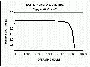
Figure 1 shows the typical voltage characteristics observed with a lithium coin-cell battery under a fixed 100kΩ load. Dallas has designed a battery monitoring circuit that utilizes the characteristics of lithium batteries under exposure to a known load to determine if the cell remains a viable power source for battery back-up. As this load exposure also requires consumption of some small amount of the battery capacity, the frequency of this exposure was also of concern during the design definition.

Figure 1. Battery discharge plot.
** load selected to accelerate battery discharge for purposes of the graph.
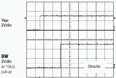
At power-up, and again approximately every 24 hours, an internal 1MΩ test resistor is connected across the battery terminals for one second and the battery voltage is sampled. During that one second period, should the battery voltage (VBAT) fall below a factory-programmed battery warning trip-point (~2.6V), the battery warning output (BW) will be asserted. (see Figure 2) Once asserted, battery testing will be performed approximately every 5 seconds to detect battery removal, and BW will remain active until the weak battery is physically removed and replaced with a fresh cell. Once a fresh cell has been attached, the first passing test result will deassert the BW output and the test interval will return to 24 hours. (see Figure 3) BW is an open-drain output driver.
Battery replacement, in the case of the PowerCap products, should generally be performed when system power is on so that the internal memory content is not corrupted. Normal memory write/read operations are not inhibited while BW is active, but preservation of the data during a power loss cannot be assured. Due to the 5 second test interval, it is required that the battery be removed for more than one test interval, or about 7 seconds, prior to attaching a new battery.
The battery is retested after each power-up, even if BW had been active at power-down.

Figure 2. Power-on battery test fails (VBAT = 2.55V).

Figure 3. Battery Test Passes with Fresh Cell (VBAT = 3.15V).
Based upon the characteristics of the end-of-life voltage profile on the primary batteries used, the occurrence of a valid BW signal should provide the user roughly 500 hours (~3 weeks) advanced notice of an impending battery failure.
打开APP阅读更多精彩内容
Dallas Semiconductor offers a variety of products that incorporate lithium coin-cell batteries. In some applications, the ability to monitor the battery status is desired to prevent any accidental loss of data when the battery is approaching its useful end-of-life. Battery monitoring is an integral function of the DS1330, DS1345, DS1350 NV SRAM PowerCap Modules, as well as the DS38464 NV SRAM SIMM.
This battery monitoring feature is also featured for sorting in our Parametric Search of memory products at http://para.maxim-ic.com/compare.asp?Fam=Memory&Tree=Memory&HP=Memory.cfm
Which Applications Might Require Battery Monitoring?
In field installations requiring very long service lifetimes or those where the environment may introduce some uncertainty in the overall reliability of the battery back-up system, some ability to periodically check the remaining battery capacity is beneficial.Installations such as servers or RAID applications that are designed to be 'always-on' rely on the NV SRAM to preserve mission-critical data should a power outage occur. Reliable and expedient system recovery after power restoration is therefore a fundamental necessity, and may warrant some additional overhead in the system architecture.
How Does the Battery Monitoring Circuit Work?
As outlined in AN505, there are several characteristics of lithium coin-cell batteries that must be understood to accurately predict the service lifetime of the battery. With the flat voltage characteristics of lithium batteries over time, and faced with the environmental variables that an NV SRAM module might be exposed to during the system's life cycle, use of simple open-circuit voltage (OCV) monitoring is not a sufficient gauge of the remaining battery capacity.Figure 1 shows the typical voltage characteristics observed with a lithium coin-cell battery under a fixed 100kΩ load. Dallas has designed a battery monitoring circuit that utilizes the characteristics of lithium batteries under exposure to a known load to determine if the cell remains a viable power source for battery back-up. As this load exposure also requires consumption of some small amount of the battery capacity, the frequency of this exposure was also of concern during the design definition.

Figure 1. Battery discharge plot.
** load selected to accelerate battery discharge for purposes of the graph.
At power-up, and again approximately every 24 hours, an internal 1MΩ test resistor is connected across the battery terminals for one second and the battery voltage is sampled. During that one second period, should the battery voltage (VBAT) fall below a factory-programmed battery warning trip-point (~2.6V), the battery warning output (BW) will be asserted. (see Figure 2) Once asserted, battery testing will be performed approximately every 5 seconds to detect battery removal, and BW will remain active until the weak battery is physically removed and replaced with a fresh cell. Once a fresh cell has been attached, the first passing test result will deassert the BW output and the test interval will return to 24 hours. (see Figure 3) BW is an open-drain output driver.
Battery replacement, in the case of the PowerCap products, should generally be performed when system power is on so that the internal memory content is not corrupted. Normal memory write/read operations are not inhibited while BW is active, but preservation of the data during a power loss cannot be assured. Due to the 5 second test interval, it is required that the battery be removed for more than one test interval, or about 7 seconds, prior to attaching a new battery.
The battery is retested after each power-up, even if BW had been active at power-down.

Figure 2. Power-on battery test fails (VBAT = 2.55V).

Figure 3. Battery Test Passes with Fresh Cell (VBAT = 3.15V).
Based upon the characteristics of the end-of-life voltage profile on the primary batteries used, the occurrence of a valid BW signal should provide the user roughly 500 hours (~3 weeks) advanced notice of an impending battery failure.
How Should the Battery Warning Output be Monitored?
The BW output is an open-drain device, and requires an external pullup resistor (~3kΩ-10kΩ) to VCC to achieve a Logic 1 output state. When asserted, the BW pin can sink up to 10mA. It is recommended to connect this pin to a available interrupt or I/O input on the user's microprocessor device. Due to the battery monitoring periodicity, check the BW state at least once every 24 hours if not tied directly to a microprocessor hardware interrupt.What Corrective Action Should be Taken when a Battery Warning is Observed?
Depending upon the system, corrective action could potentially range anywhere from illumination of a panel indicator or sending warning messages to the operator to something more elaborate as an automated service dispatch function using external communications ports and a predetermined error protocol. In any case, the relative safety of many days of prior warning should allow the user sufficient reaction time to execute a controlled procedure for battery replacement without experiencing data loss. Questions/comments/suggestions concerning this application note can be sent t MixedSignal.Apps@dalsemi.com
声明:本文内容及配图由入驻作者撰写或者入驻合作网站授权转载。文章观点仅代表作者本人,不代表电子发烧友网立场。文章及其配图仅供工程师学习之用,如有内容侵权或者其他违规问题,请联系本站处理。
举报投诉
评论(0)
发评论
-
elecfans网友 2014-02-04
0 回复 举报-1' 收起回复
- 相关推荐
- 热点推荐
- Battery
-
ADBMS6948: 16-Channel Battery Pack Monitoring System Data Sheet ADBMS6948: 16-Channel Battery Pack Monitoring System Data Sheet2023-10-12 138
-
电池备份NV SRAM和NOVRAMS之间的比较2023-01-10 2033
-
NV-SRAM是什么,它的主要特征是什么2022-06-10 1421
-
NV-SRAM与BBSRAM之间的比较2022-01-25 519
-
赛普拉斯NV-SRAM的解决方案,它的优势是什么2020-12-22 843
-
非易失性存储器NV-SRAM的关键属性是什么2020-12-18 1210
-
DS1249W 2048kb非易失(NV) SRAM2010-11-24 1073
-
DS1265W 8Mb非易失(NV) SRAM2010-11-07 985
-
DS1330 256k非易失(NV) SRAM2010-10-22 1897
-
DS1350 4096k非易失(NV) SRAM2010-10-21 1204
-
MAX11068,pdf (battery-monitoring smart data acquisition)2010-07-05 1686
-
Battery Monitoring in NV SRAM2009-04-24 1733
-
新一代NV SRAM技术2008-11-26 1226
全部0条评论

快来发表一下你的评论吧 !

