

实现MAXQ2000微控制器的JTAG加载主机
应用电子电路
904人已加入
描述
摘要:MAXQ®微控制器提供的JTAG启动加载程序使外部JTAG主机能够利用一组标准命令,轻松地识别MAXQ微控制器,并对其进行编程。本应用笔记中的代码可以用作构建全功能JTAG启动加载主机应用程序的出发点。主机应用程序能够识别、初始化、装载、验证支持标准启动加载程序命令集MAXQ微控制器的程序和数据存储器内容。
本应用笔记涉及到实现MAXQ2000 JTAG启动加载程序主机的基本步骤。这些步骤包括JTAG端口接口,测试访问端口(TAP)控制器通信,激活启动加载程序模式,向基于ROM的启动加载程序发送命令等。由于所有MAXQ器件的JTAG端口工作情况一般相同,MAXQ启动加载程序采用共享命令集工作,因此,在实现MAXQ微控制器JTAG启动加载程序主机时可以参考本应用笔记涉及到的大部分主题(以及大部分实例代码)。
除了串口,应用笔记并没有使用MAXQ2000的特殊功能。这表明,这里的实例代码很容易重新用于程序存储器空间足够大的任何MAXQ20器件。代码以MAXQ汇编语言编写,采用MAX-IDE开发环境编译。可以下载这些代码。
在原型区安装一个2 x 5引脚插座对主机MAXQ2000评估板进行改动,原型区提供JTAG电缆主机侧连接。插座的引脚符合标准MAXQ JTAG插座布局,按照表1所示进行连接。
表1. MAXQ2000 JTAG连接
不需要对从机MAXQ2000评估板进行改动。按照上面的说明在主机MAXQ2000评估板的原型区安装2 x 5 JTAG插座。然后,将两块评估板连接起来;主机评估板原型区的2 x 5 JTAG插座和从机评估板的标准JTAG插座(J4)之间连接标准2 x 5 JTAG电缆(这种JTAG一般用于连接串口至JTAG板和MAXQ评估板)。JTAG 2 x 5连接器含在MAXQ2000评估套件中。
为简化起见,没有对主机评估板和从机评估板的JTAG电缆电源或者参考电压连接进行试验。而是设置两块评估板采用同一VDDIO电压(大约3.6V)工作。这种设置保证了主机和从机MAXQ2000采用公共I/O电源电平工作。
从机评估板还在插座J3上安装了LCD子卡(MAXQ2000-K01)。表2列出了两块电路板(以及串口至JTAG电路板)的跳线和DIP开关设置。注意:应断开未列出的所有跳线。图1所示为最终设置。
表2. 电路板开关和跳线设置
图1. JTAG演示板配置
表3. JTAG接口信号
从技术上看,nRESET引脚并不是JTAG接口的组成部分。它含在JTAG电缆中,使JTAG主机能够复位从机微控制器。重新设置从机微控制器是进入启动加载程序模式需要的步骤,如果JTAG通信意外中断,也需要重新设置从机微控制器。
JTAG接口是全双工的,数据在TDI线上由主机送入从机,同时,数据在TDO线上由从机送入主机。从机在TCK上升沿对到达数据(在TDI和TMS上)进行采样,在TCK下降沿,数据在TDO上被驱动输出至主机。对于到达和输出数据,最先传送最低有效位。本应用笔记简要介绍JTAG接口和TAP控制器,以解释实例代码的工作。关于这些特性的详细讨论,请参考MAXQ系列用户指南(English only)的测试访问端口(TAP)、在线调试模式、在系统编程等章节,公司网站上有该文档。
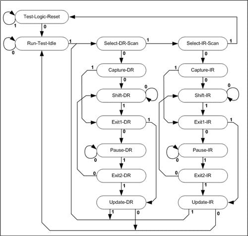
图2. 测试访问端口(TAP)状态机
TAP控制器的状态机提供对两个控制寄存器的访问,而寄存器提供启动加载程序接口、调试接口以及其他功能。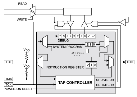
图3. TAP控制器中的寄存器访问
如图3所示,DR根据IR值而指向三个内部寄存器之一。
由于这一例子中的从机MAXQ2000安装了8MHz时钟晶振,主机能够驱动JTAG时钟达到1MHz,而不会出现问题。对于这个例子,100kHz JTAG时钟足够了。
对于所有的JTAG移位寄存器操作,随着新数值的移入,寄存器的当前内容被移出(由TDO)。但是,移出的数值总是固定的(001b);这是由JTAG标准在测试JTAG接口功能时决定的。
比特移入和移出移位寄存器的过程(IR或者DR)是一样的;TAP状态机必须分别处于Shift-IR或者Shift-DR状态,TAP控制器在每个TCK周期的上升沿对输入比特(在TDI)进行采样,而在TCK周期下降沿驱动输出比特(在TDO)。
作为一个例子,在表4中,JTAG主机将数值100b (系统编程模式)移入到IR寄存器中。IR寄存器开始设置旁路值011b;TAP控制器最初为Run-Test-Idle状态。如下面的图4所示,比特以最低有效位在前、最高有效位在后移入(移出)TAP控制器。因此,在第一个移位周期,新数值的第0位被移入,旧数值的第0位被移出。
表4. 指令寄存器移位实例
下面是执行这一操作的例程shiftIR3。
激活系统编程模式后,装入和卸载DR寄存器的操作如下。
然而,启动加载程序代码和JTAG主机并不同步。只要JTAG时钟保持低于MAXQ系统时钟1/8的最大值,由于JTAG是同步接口,因此,两路时钟的确切值并不影响通信。但是,MAXQ系统时钟速率以及接收到的启动加载程序命令特性将决定启动加载程序接收命令和发送回应之间的延时。例如,1MHz运行的MAXQ2000响应某一启动加载程序命令的时间要比10MHz的MAXQ2000时间长,即使两个微控制器都可以采用100kHz的JTAG时钟进行通信。只是读并返回信息的命令,例如返回ROM标志ID的命令以及从程序存储器读取的命令,花费的时间也要少于编程闪存操作等命令。
通过JTAG接口传送的数据没有被缓冲。如果在前一命令被读取之前,发送了另一10位命令,前一命令的结果丢失。ROM代码和TAP控制器保证前一数据被JTAG主机卸载前,启动加载程序不会发送其他数据,但反方向还是需要同步。JTAG主机需要通过某种方式知道移入DR的前一字节是否已经被启动加载程序读取了。这样,JTAG主机能够知道什么时候发送下一字节。采用的方法是利用TAP控制器发送的其他两个状态位,以及启动加载程序输出的每个8位字节。
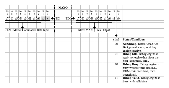
图4. 通过DR的移位数据和状态位
2x5 如上面的图4所示,在TAP调试模式下,移入和移出DR的数据包括8个数据位(第2位到第9位)和两个状态位(第0位和第1位)。当JTAG主机移入数据时,只使用8个数据位。TAP控制器没有使用的两个状态位(也必须被移入),可以被设置为零,或者任何其他值。
在TAP控制器移出的10位数值中,两个状态位提供启动加载程序或者调试引擎的状态信息。当启动加载程序运行时,一般只能达到最后两个状态(调试忙或者调试有效),这是因为其他两个状态值不会出现在启动加载程序模式中。(参见图4中的状态/条件)
对于其他的MAXQ启动加载程序,MAXQ2000启动加载程序提供的命令被划分成从0到15的命令集。每一命令以命令字节开始,它包括命令集(前四个比特)以及命令专用数(后四个比特),如表5所示。作为一般规则,命令集0的命令本质上用于提供信息,所有器件均采用它;其他命令集可选。为确定某一MAXQ器件支持的命令集,请参考器件文档。命令集0的命令05h (获得支持的命令)返回一个位掩码,说明启动加载程序支持的其他命令集。
MAXQ2000支持以下的启动加载程序命令集。
表5. MAXQ加载程序命令集
作为演示的一部分,我们的实例程序获得该信息,然后打印输出至串口。用于实现该功能的例程是getBanner。
取决于MAXQ器件,这一02h (主机擦除)命令可能需要几秒钟的时间来完成。由于这是一个单字节命令,确定该命令什么时候完成的最简单方法是不断发送无操作(00h)命令,其后是1毫秒的延迟,直到启动加载程序返回3Eh,表明命令已经完成。下面的 masterErase例程说明了这一方法。
如果最后一条命令成功完成,状态码总是00h (无错误)。非零状态码指示有错误。MAXQ2000用户指南附录(English only)列出了所有的状态码;这里列出了几个常见错误码。
装入MAXQ2000的代码基于下面的简单演示工程。
在装入代码前,JTAG通信演示应用程序首先告诉用户输入一个4位十进制数,然后修改要装入的应用程序,如下所示。
硬件
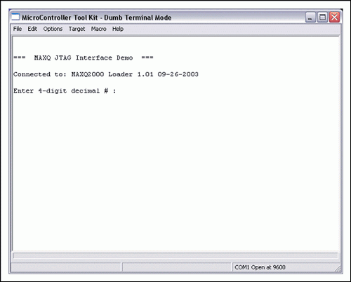
图5. 演示应用程序,串口提示符
现在输入一个4位十进制数;不需要随后按下回车键。演示应用程序会完成剩下的操作(主机擦除、装入代码和卸载代码),并输出结果,以及从程序存储器中卸载的十六进制字节值,如图6所示。
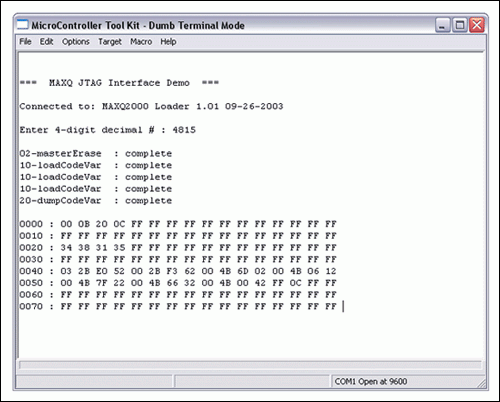
图6. 演示应用程序,串口输出
打开APP阅读更多精彩内容
简介
具有可在线编程的程序存储器(例如MAXQ2000和MAXQ3210)的MAXQ微控制器一般还提供基于ROM的启动加载程序,利用微控制器的JTAG兼容调试端口,实现程序存储器的加载。尽管不同的器件有不同的JTAG启动加载程序功能,但是通常都包括程序和数据存储器写、读、验证和擦除等命令。有的器件为启动加载程序提供其他接口(例如,串口或者SPI™接口),而JTAG接口是最常用的,原因有两个。第一,JTAG接口支持在线调试功能,第二,最终用户应用程序并没有充分发挥JTAG接口的功能(与串口不同)。一旦加载程序代码后,可选择的加密机制限制了对启动加载程序的访问,或在线调试。关于每个MAXQ器件功能的详细信息,请参考产品说明,包括数据资料和用户指南等。本应用笔记涉及到实现MAXQ2000 JTAG启动加载程序主机的基本步骤。这些步骤包括JTAG端口接口,测试访问端口(TAP)控制器通信,激活启动加载程序模式,向基于ROM的启动加载程序发送命令等。由于所有MAXQ器件的JTAG端口工作情况一般相同,MAXQ启动加载程序采用共享命令集工作,因此,在实现MAXQ微控制器JTAG启动加载程序主机时可以参考本应用笔记涉及到的大部分主题(以及大部分实例代码)。
除了串口,应用笔记并没有使用MAXQ2000的特殊功能。这表明,这里的实例代码很容易重新用于程序存储器空间足够大的任何MAXQ20器件。代码以MAXQ汇编语言编写,采用MAX-IDE开发环境编译。可以下载这些代码。
硬件设置
采用一对MAXQ2000评估(EV)板来开发本应用笔记的实例代码。需要两块MAXQ2000评估板执行这里的软件。一个MAXQ2000 (JTAG主机)运行实例代码;第二个MAXQ2000用作JTAG从机,由主机对它重新编程。两个MAXQ2000微控制器都采用了标准8.00MHz晶振。在原型区安装一个2 x 5引脚插座对主机MAXQ2000评估板进行改动,原型区提供JTAG电缆主机侧连接。插座的引脚符合标准MAXQ JTAG插座布局,按照表1所示进行连接。
表1. MAXQ2000 JTAG连接
| JTAG Header Pin | JTAG Cable Function | MAXQ2000 JTAG Master Connection |
MAXQ2000 JTAG Slave Connection |
| 1 | TCK (Test Clock) | P0.0 (Output) | P4.0 (Input) |
| 2 | GND | GND | GND |
| 3 | TDO (Test Data Out) | P0.1 (Input) | P4.3 (Output) |
| 4 | VREF | – | – |
| 5 | TMS (Test Mode Select) | P0.2 (Output) | P4.2 (Input) |
| 6 | nRESET | P0.4 (Open Drain) | nRESET (Input) |
| 7 | Keyed pin | – | – |
| 8 | +5V | – | – |
| 9 | TDI (Test Data In) | P0.3 (Output) | P4.1 (Input) |
| 10 | GND | GND | GND |
不需要对从机MAXQ2000评估板进行改动。按照上面的说明在主机MAXQ2000评估板的原型区安装2 x 5 JTAG插座。然后,将两块评估板连接起来;主机评估板原型区的2 x 5 JTAG插座和从机评估板的标准JTAG插座(J4)之间连接标准2 x 5 JTAG电缆(这种JTAG一般用于连接串口至JTAG板和MAXQ评估板)。JTAG 2 x 5连接器含在MAXQ2000评估套件中。
为简化起见,没有对主机评估板和从机评估板的JTAG电缆电源或者参考电压连接进行试验。而是设置两块评估板采用同一VDDIO电压(大约3.6V)工作。这种设置保证了主机和从机MAXQ2000采用公共I/O电源电平工作。
从机评估板还在插座J3上安装了LCD子卡(MAXQ2000-K01)。表2列出了两块电路板(以及串口至JTAG电路板)的跳线和DIP开关设置。注意:应断开未列出的所有跳线。图1所示为最终设置。
表2. 电路板开关和跳线设置
| Board | Switch or Jumper | Setting | Notes |
| Serial-to-JTAG Board | JH1 | Connected | |
| JH2 | Connected | ||
| JH3 | Connected | Supplies 5V power over JTAG cable | |
| Master MAXQ2000 EV Kit | JU1 | Pins 1 and 2 connected | Powers VDD from 2.5V supply |
| JU2 | Pins 1 and 2 connected | Powers VDDIO from 3.6V supply | |
| JU3 | Pins 1 and 2 connected | Powers VLCD from 3.6V supply | |
| JU11 | Connected | Powers kit board from JTAG 5V supply | |
| DIP SW1 | Switches #4 and #8 ON; all other switches OFF | Enables serial port 0 output to J5 | |
| DIP SW3 | All switches OFF | ||
| DIP SW6 | All switches OFF | ||
| Slave MAXQ2000 EV Kit | JU1 | Pins 1 and 2 connected | Powers VDD from 2.5V supply |
| JU2 | Pins 1 and 2 connected | Powers VDDIO from 3.6V supply | |
| JU3 | Pins 1 and 2 connected | Powers VLCD from 3.6V supply | |
| DIP SW1 | All switches OFF | ||
| DIP SW3 | All switches OFF | ||
| DIP SW6 | All switches OFF |
图1. JTAG演示板配置
MAXQ JTAG接口
MAXQ微控制器的JTAG接口由四条信号线组成,用于测试访问端口(TAP)控制器的信息输入和输出。TAP控制器支持对MAXQ启动加载程序的访问,提供在线调试功能(注意,调试主机的实现和启动加载程序主机的实现类似,但是已经超出了本应用笔记的范围)。表3对四条JTAG信号线进行了说明。表3. JTAG接口信号
| JTAG Signal | Signal Name | Direction (Master) | Direction (Slave) | Signal Description |
| TMS | Test Mode Select | Output | Input | This signal line, along with the TCK line, is used to shift the TAP controller from one operational state to the next. |
| TCK | Test Clock | Output | Input | This signal provides the clock for the JTAG interface. The JTAG clock is limited to a maximum of the slave's clock frequency divided by 8. For example, if the slave is running at a clock frequency of 8MHz, the JTAG clock at TCK cannot run any faster than 1MHz. |
| TDI | Test Data In | Output | Input | This signal carries data that is sent from the master to the slave. |
| TDO | Test Data Out | Input | Output | This signal carries data that is sent from the slave back to the master. |
从技术上看,nRESET引脚并不是JTAG接口的组成部分。它含在JTAG电缆中,使JTAG主机能够复位从机微控制器。重新设置从机微控制器是进入启动加载程序模式需要的步骤,如果JTAG通信意外中断,也需要重新设置从机微控制器。
JTAG接口是全双工的,数据在TDI线上由主机送入从机,同时,数据在TDO线上由从机送入主机。从机在TCK上升沿对到达数据(在TDI和TMS上)进行采样,在TCK下降沿,数据在TDO上被驱动输出至主机。对于到达和输出数据,最先传送最低有效位。本应用笔记简要介绍JTAG接口和TAP控制器,以解释实例代码的工作。关于这些特性的详细讨论,请参考MAXQ系列用户指南(English only)的测试访问端口(TAP)、在线调试模式、在系统编程等章节,公司网站上有该文档。
TAP控制器通信
TAP控制器围绕状态机进行构建,如下面的图2所示。TAP状态机中有16个分立状态。根据TMS信号值,在TCK的上升沿从一个状态向下一个状态转变。例如,如果TAP控制器处于Select-DR-Scan状态,TCK出现了上升沿:- 如果TMS = 1,TAP控制器将转换到Select-IR-Scan状态。
- 如果TMS = 0,TAP控制器将转换到Capture-DR状态。
- 5个'1'转换(保持TMS高电平,同步TCK 5个周期)总是使状态机回到Test-Logic-Reset,而不论起始状态如何。这表明,如果不确定TAP控制器当前的状态,或者在某些情况下JTAG主机和从机间的通信中断,总是可以通过同步5个'1'转换,使TAP控制器回到已知状态。
- 即使TCK时钟继续运行,也可以暂停JTAG通信,不确定地保持在Run-Test-Idle、Pause-DR或者Pause-IR状态,而不影响TAP控制器的状态。

图2. 测试访问端口(TAP)状态机
TAP控制器的状态机提供对两个控制寄存器的访问,而寄存器提供启动加载程序接口、调试接口以及其他功能。
- IR (指令寄存器)宽度总是3位。该寄存器可以用作指数寄存器,控制DR的功能(参见下面)。
- DR (数据寄存器)是TAP控制器中几个寄存器的访问点。当比特移入或者移出DR时实际访问的寄存器取决于IR当前值。

图3. TAP控制器中的寄存器访问
如图3所示,DR根据IR值而指向三个内部寄存器之一。
- 如果IR = 011b,TAP控制器处于Bypass模式。在这一模式下(这是TAP控制器的默认模式),通过TDO,移入到DR (通过TDI)的数据被直接移回送出。通过TAP控制器移动数据并没有改变内部寄存器。
- 设置IR = 100b,使TAP控制器处于System Programming模式。在这种模式下,移入DR中的数据被移入到3位系统编程寄存器中。该寄存器(也可以通过MAXQ微控制器ICDF寄存器的[3:1]位进行访问)控制MAXQ复位后进入正常程序执行模式还是启动加载程序模式。如果使能启动加载程序模式,它还控制启动加载程序使用哪一接口(JTAG、串口或者SPI)。
- 设置IR = 010b,使TAP控制器进入Debug模式。在这一模式下,移入DR的数据被移入到内部10位调试寄存器中,可以被启动加载程序读取。启动加载程序输出的数据也通过该寄存器,在TDO上被移回送出(以及两个状态位)。该寄存器被用于启动加载程序模式和在线调试模式时的数据传送。
控制JTAG端口和复位线
从机MAXQ2000 (TMS, TCK, TDO和TDI) JTAG/TAP端口的四条线以及nRESET线分别连接至主机MAXQ2000的一个端口引脚。控制JTAG接口的第一步是正确配置这些线。#define TCK PO0.0 ; Test Clock - Master output #define TDO PI0.1 ; Test Data Out - Slave output, master input #define TMS PO0.2 ; Test Mode Sel - Master output #define TDI PO0.3 ; Test Data In - Master output #define RST PD0.4 ; Reset - Master open-drain output (on 1)四条JTAG线工作在标准驱动模式下。从主机角度看,TMS、TCK和TDI总是被驱动为输出,而TDO (由从机驱动)总是为输入。JTAG线的方向固定,不是双向的。nRESET线是特殊情况,被配置为主机侧开漏输出。通常,从机将自己的nRESET线拉至高电平,因此,主机只能将该线拉低(复位从机时),或者完全释放它(在其他所有时间)。主机不应将从机的nRESET线驱动为高电平。
;==============================================================================
;=
;=  initializeJTAG
;=
;=  Sets up the port pins for the JTAG interface.
;=
;=  Inputs   : None
;=  Outputs  : None
;=  Destroys : None
;=

initializeJTAG:
   move    PD0.0, #1      ; TCK - master output
   move    PO0.0, #1      ; Drive high
   move    PD0.1, #0      ; TDO - master input
   move    PO0.1, #1      ; Weak pullup on
   move    PD0.2, #1      ; TMS - master output
   move    PO0.2, #1      ; Drive low
   move    PD0.3, #1      ; TDI - master output
   move    PO0.3, #1      ; Drive high
   move    PD0.4, #0      ; RST - open drain when 1, tristate when 0
   move    PO0.4, #0      ; Weak pullup off
   ret
端口引脚初始化之后,采用例程clock0和clock1来同步TMS线上的静态0和1,使TAP控制器从一个状态转换到另一状态。只要JTAG时钟速率保持低于从机微控制器系统时钟速率1/8的最大值,JTAG时钟可以采用任何频率。这里不需要考虑主机的系统时钟速率;它不需要和从机系统时钟速率相匹配。主机可以比从机运行的快或者慢,而不会导致出现JTAG通信问题。
由于这一例子中的从机MAXQ2000安装了8MHz时钟晶振,主机能够驱动JTAG时钟达到1MHz,而不会出现问题。对于这个例子,100kHz JTAG时钟足够了。
#define   JCLOCK           40        ; 100kHz : (((10us / (1/8MHz)) / 2)

;==============================================================================
;=
;=  clock0
;=
;=  Clocks a zero TMS bit into the JTAG interface.
;=
;=  Inputs   : None
;=  Outputs  : None
;=  Destroys : LC[0]

clock0:
   move    TMS, #0           ; Drive TMS low
   move    LC[0], #JCLOCK
   djnz    LC[0], $
   move    TCK, #1           ; Clock rising edge
   move    LC[0], #JCLOCK
   djnz    LC[0], $
   move    TCK, #0           ; Clock falling edge
   move    LC[0], #JCLOCK
   djnz    LC[0], $
   ret


;==============================================================================
;=
;=  clock1
;=
;=  Clocks a one TMS bit into the JTAG interface.
;=
;=  Inputs   : None
;=  Outputs  : None
;=  Destroys : LC[0]

clock1:
   move    TMS, #1           ; Drive TMS high
   move    LC[0], #JCLOCK
   djnz    LC[0], $
   move    TCK, #1           ; Clock rising edge
   move    LC[0], #JCLOCK
   djnz    LC[0], $
   move    TCK, #0           ; Clock falling edge
   move    LC[0], #JCLOCK
   djnz    LC[0], $
   ret
利用这两个例程,我们可以增加另一个例程来初始化TAP控制器,迫使它回到Test-Logic-Reset状态。注意Test-Logic-Reset状态,正如其名称的含义,它对TAP逻辑进行彻底复位,包括确定启动加载程序是否使能以及启动加载程序使用哪一接口位(SPE和PSS[1:0])。因此,一旦进入启动加载程序模式,设置TAP控制器为Test-Logic-Reset,对器件进行复位,退出启动加载程序模式。演示应用程序中使用的JTAG例程(除了testLogicReset本身之外)都假定TAP控制器在例程启动时处于Run-Test-Idle状态。在JTAG通信期间,TAP控制器在不同状态间转换;例程最后,TAP控制器总是返回到Run-Test-Idle。
;==============================================================================
;=
;=  testLogicReset
;=     clock0, clock1
;=
;=  Resets the JTAG/TAP controller to its starting state.
;=
;=  Inputs   : None
;=  Outputs  : None
;=  Destroys : LC[0]
;=

testLogicReset:
   call    clock1
   call    clock1
   call    clock1
   call    clock1
   call    clock1
   call    clock1
   call    clock1
   call    clock0            ; Brings us to Run-Test-Idle
   ret
写入TAP指令寄存器
TAP状态机向下转换到Shift-IR状态,同步输入一个新的3位数值,将数值装入TAP控制器的IR。在进入Update-IR状态之前,该数值并没有实际从移位寄存器复制到指令寄存器中。对于所有的JTAG移位寄存器操作,随着新数值的移入,寄存器的当前内容被移出(由TDO)。但是,移出的数值总是固定的(001b);这是由JTAG标准在测试JTAG接口功能时决定的。
比特移入和移出移位寄存器的过程(IR或者DR)是一样的;TAP状态机必须分别处于Shift-IR或者Shift-DR状态,TAP控制器在每个TCK周期的上升沿对输入比特(在TDI)进行采样,而在TCK周期下降沿驱动输出比特(在TDO)。
;==============================================================================
;=
;=  shift
;=
;=  In a shift register state, clocks in a TDI bit and clocks out a TDO bit.
;=
;=  Inputs   : C - Bit to shift in to TDI.
;=  Outputs  : C - Bit shifted out from TDO.
;=  Destroys : PSW, LC[0]
;=

shift:
   jump    C, shift_bit1
shift_bit0:
   move    TDI, #0           ; Shift in zero bit
   jump    shift_bitEnd
shift_bit1:
   move    TDI, #1           ; Shift in one bit
   jump    shift_bitEnd
shift_bitEnd:
   move    LC[0], #JCLOCK
   djnz    LC[0], $
   move    TCK, #1           ; Rising edge, TDI is sampled
   move    LC[0], #JCLOCK
   djnz    LC[0], $
   move    TCK, #0           ; Falling edge, TDO is driven out
   move    LC[0], #JCLOCK
   djnz    LC[0], $
   move    C, TDO            ; Latch TDO value
   ret
对于传送的每一位,除了最后一位之外,TMS必须保持低电平。这非常重要,因为当每一位移入和移出时,状态机保持在Shift-IR或者Shift-DR状态。在最后一个比特周期,TMS必须被驱动为高电平,这样,随着最后一位的输入和输出,TAP控制器将进入Exit1-DR或者Exit1-IR状态。
作为一个例子,在表4中,JTAG主机将数值100b (系统编程模式)移入到IR寄存器中。IR寄存器开始设置旁路值011b;TAP控制器最初为Run-Test-Idle状态。如下面的图4所示,比特以最低有效位在前、最高有效位在后移入(移出)TAP控制器。因此,在第一个移位周期,新数值的第0位被移入,旧数值的第0位被移出。
表4. 指令寄存器移位实例
| TCK | TMS | TDI | TDO | TAP State | Shift Register | Instruction Register | ||||
| bit 2 | bit 1 | bit 0 | bit 2 | bit 1 | bit 0 | |||||
| 0 | 1 | x | x | Run-Test-Idle | x | x | x | 0 | 1 | 1 |
| 1 | 1 | x | x | Select-DR-Scan | x | x | x | 0 | 1 | 1 |
| 0 | 1 | x | x | Select-DR-Scan | x | x | x | 0 | 1 | 1 |
| 1 | 1 | x | x | Select-IR-Scan | x | x | x | 0 | 1 | 1 |
| 0 | 0 | x | x | Select-IR-Scan | x | x | x | 0 | 1 | 1 |
| 1 | 0 | x | x | Capture-IR | 0 | 0 | 1 | 0 | 1 | 1 |
| 0 | 0 | x | x | Capture-IR | 0 | 0 | 1 | 0 | 1 | 1 |
| 1 | 0 | x | x | Shift-IR | 0 | 0 | 1 | 0 | 1 | 1 |
| 0 | 0 | 0 | x | Shift-IR | 0 | 0 | 1 | 0 | 1 | 1 |
| 1 | 0 | 0 | x | Shift-IR | 0 | 0 | 1 | 0 | 1 | 1 |
| 0 | 0 | 0 | 1 | Shift-IR | 0 | 0 | 0 | 0 | 1 | 1 |
| 1 | 0 | 0 | 1 | Shift-IR | 0 | 0 | 0 | 0 | 1 | 1 |
| 0 | 1 | 1 | 0 | Shift-IR | 0 | 0 | 0 | 0 | 1 | 1 |
| 1 | 1 | 1 | 0 | Exit1-IR | 0 | 0 | 0 | 0 | 1 | 1 |
| 0 | 1 | x | 0 | Exit1-IR | 1 | 0 | 0 | 0 | 1 | 1 |
| 1 | 1 | x | 0 | Update-IR | 1 | 0 | 0 | 1 | 0 | 0 |
| 0 | 0 | x | x | Update-IR | 1 | 0 | 0 | 1 | 0 | 0 |
| 1 | 0 | x | x | Run-Test-Idle | x | x | x | 1 | 0 | 0 |
下面是执行这一操作的例程shiftIR3。
;==============================================================================
;=
;=  shiftIR3
;=     clock0, clock1, shift
;=
;=  Shifts a 3-bit value into the IR register.
;=
;=  Inputs   : A[0] - Low three bits contain value to shift into IR
;=  Outputs  : None
;=  Destroys : AP, APC, A[0], PSW, LC[0]
;=

shiftIR3:
   move    APC, #80h         ; Acc => A[0], turn off auto inc/dec
   call    clock1            ; (Select DR Scan)
   call    clock1            ; (Select IR Scan)
   call    clock0            ; (Capture IR - loads 001b to shift register)
   call    clock0            ; (Shift IR)
   move    TMS, #0           ; Drive TMS low
   move    C, TDO            ; xxxxx210   c = s
   rrc                       ; sxxxxx21   c = 0
   call    shift             ; Shift in IR bit 0
   rrc                       ; ssxxxxx2   c = 1
   call    shift             ; Shift in IR bit 1
   rrc                       ; sssxxxxx   c = 2
   move    TMS, #1           ; Drive TMS high for last bit
   call    shift             ; Shift in IR bit 2 (Exit1 IR)
   call    clock1            ; (Update IR)
   call    clock0            ; (Run Test Idle)
   ret
写入TAP数据寄存器
数值移入或者移出TAP控制器DR的操作与装入/卸载IR的方式相似。通常,只有当IR被设置为两个数值之一时才能进行这一操作:100b (使TAP控制器进入系统编程模式)或者010b (使TAP控制器进入调试模式)。激活系统编程模式后,装入和卸载DR寄存器的操作如下。
- DR寄存器移入和移出宽度为3比特。所有三个比特都代表有效数据。
- 当到达Update-DR状态时,送入DR寄存器的数值被复制到从机微控制器的内部系统编程寄存器中。这三个比特的用法如下。
- 从机微控制器可访问第0位(读/写),它作为寄存器位ICDF.1 (SPE),也被称为系统编程使能位。复位后,程序ROM检查该位,确定应进入启动加载程序模式(SPE = 1)还是正常程序执行模式(SPE = 0)。
- 从机微控制器可访问第1位和第2位(读/写),它作为寄存器位ICDF.2-3 (PSS0-PSS1),也被称为编程源选择位。对于能够为启动加载程序提供多个接口的微控制器,例如MAXQ2000,这些位用于当SPE = 1时应选择哪一启动加载程序接口。当SPE = 0 (正常程序执行模式)时,这些位的设置不起作用。
- DR寄存器传送出去的数值是系统编程寄存器以前的数值(当进入Capture-DR状态后,锁存到移位寄存器中)。
- DR寄存器移入和移出宽度为10比特。对于移出数据,所有10个比特都代表有效数据(8个数据位和2个状态位)。对于移入数据,只使用了8个数据位;没有使用两个状态位。
- 然后,将移入DR寄存器的高8位卸载,作为启动加载程序命令的一部分,被启动加载程序(从程序ROM中运行)读取。
- 移出DR寄存器的10个比特含有8位由启动加载程序装入的数值(作为命令输出的一部分),以及由TAP控制器设置的两个状态信息位。
;==============================================================================
;=
;=  shiftDR3
;=
;=  Shifts a 3-bit value into the DR register.  This operation should only be
;=  performed when IR =100b (System Programming Mode).
;=
;=  Inputs   : A[0] - Low 3 bits contain value to shift into SPB (PSS1:PSS0:SPE)
;=  Outputs  : None
;=  Destroys : AP, APC, A[0], PSW, LC[0]

shiftDR3:
   move    APC, #80h         ; Acc => A[0], turn off auto inc/dec
   call    clock1            ; (Select DR Scan)
   call    clock0            ; (Capture DR)
   call    clock0            ; (Shift DR)
   move    TMS, #0           ; Drive TMS low
   move    C, TDO            ; xxxxx210   c = s
   rrc                       ; sxxxxx21   c = 0
   call    shift             ; Shift in DR bit 0
   rrc                       ; ssxxxxx2   c = 1
   call    shift             ; Shift in DR bit 1
   rrc                       ; sssxxxxx   c = 2
   move    TMS, #1           ; Drive TMS high for last bit
   call    shift             ; Shift in DR bit 2 (Exit1 DR)
   call    clock1            ; (Update DR)
   call    clock0            ; (Run Test Idle)
   ret


;==============================================================================
;=
;=  shiftDR
;=     clock0, clock1, shift
;=
;=  Shifts a 10-bit value into and out of the DR register.  This operation
;=  should only be performed when IR = 010b (Debug/Loader Mode).
;=
;=  Inputs   : A[0]  - Byte value (input) to shift into DR
;=  Outputs  : A[0]  - Byte value (output) shifted out of DR
;=             A[1]  - Low two bits are status bits 1:0 shifted out of DR
;=             A[15] - Byte value shifted in, cached for use by shiftDR_next
;=  Destroys : AP, APC, PSW, LC[0]

shiftDR:
   move    APC, #80h         ; Acc => A[0], turn off auto inc/dec
   move    A[15], A[0]       ; Cache input byte value for use by shiftDR_next
   sla2                      ; Add two empty bits (for status)
   call    clock1            ; (Select DR Scan)
   call    clock0            ; (Capture DR)
   call    clock0            ; (Shift DR)

   move    TMS, #0           ; Drive TMS low
   move    C, TDO            ; xxxxxxxx76543210   c = s
   rrc
   call    shift             ; Shift in DR bit 0
   rrc
   call    shift             ; Shift in DR bit 1
   rrc
   call    shift             ; Shift in DR bit 2
   rrc
   call    shift             ; Shift in DR bit 3
   rrc
   call    shift             ; Shift in DR bit 4
   rrc
   call    shift             ; Shift in DR bit 5
   rrc
   call    shift             ; Shift in DR bit 6
   rrc
   call    shift             ; Shift in DR bit 7
   rrc
   call    shift             ; Shift in DR bit 8
   rrc
   move    TMS, #1           ; Drive TMS high for last bit
   call    shift             ; Shift in DR bit 9 (Exit1 DR)
   call    clock1            ; (Update DR)
   call    clock0            ; (Run Test Idle)

   push    Acc               ; sddd dddd 10xx xxxx
   sra4                      ; ssss sddd dddd 10xx
   sra2                      ; ssss sssd dddd dd10
   and     #0003h            ; ---- ---- ---- --10
   move    A[1], Acc         ; Return status bits only in A[1]
   pop     Acc
   and     #0FF00h
   xch                       ; Return data bits only in A[0]
   ret
进入JTAG程序加载模式
需要按照以下步骤使MAXQ2000进入JTAG启动加载程序模式。- 初始化TAP控制器,重新设置它,进入Test-Logic-Reset状态。
- 设置指令寄存器(IR)为100b,使能系统编程模式。
- 设置数据寄存器(DR)为001b。这使得SPE(系统编程使能)位为1,使能启动加载程序,设置PSS[1:0] (编程源选择)位为00b,选择JTAG接口。
- 保持nRESET低电平,复位MAXQ2000。
- 释放nRESET。这导致MAXQ2000指向程序ROM (8000h)中的标准复位点。程序ROM代码将检查SPE和PSS位值,相应地激活JTAG启动加载程序。在这一点,启动加载程序运行,准备接收JTAG命令。
- 设置指令寄存器(IR)为010b,使能调试模式。该模式用于和JTAG启动加载程序或者调试引擎进行通信;在这一例子中,我们将使用该模式和启动加载程序进行通信。
- 10位数据移位通过DR,开始向JTAG启动加载程序发送命令。
#define  IR_DEBUG         010b      ; Debug Mode
#define  IR_BYPASS        011b      ; Bypass Mode (default)
#define  IR_SYSTEM_PROG   100b      ; System Programming Mode (activate loader)

; System Programming Register settings

#define  SP_EXECUTE       000b      ; Bootloader disabled
#define  SP_LOAD_JTAG     001b      ; Activate JTAG bootloader
#define  SP_LOAD_UART     011b      ; Activate UART bootloader
#define  SP_LOAD_SPI      101b      ; Activate SPI bootloader (invalid on 2000)
#define  SP_RESERVED      111b      ; Reserved value

   ...

   call    initializeJTAG    ; Set up port pins for JTAG
   call    testLogicReset    ; Reset JTAG port (ending state: Run-Test-Idle)

   move    Acc, #IR_SYSTEM_PROG
   call    shiftIR3          ; Load the System Programming instruction into IR

   move    Acc, #SP_LOAD_JTAG
   call    shiftDR3          ; Enable the bootloader in JTAG interface mode

   move    RST, #1           ; Drive nRESET low
   move    Acc, #100         ; Delay for 100ms
   call    delayMS

   call    clock0            ; Remain in Run-Test-Idle

   move    RST, #0           ; Release nRESET
   move    Acc, #100         ; Delay for 100ms
   call    delayMS

   move    Acc, #IR_DEBUG
   call    shiftIR3          ; Enable access to the 10-bit debug shift register

   ;;;;  Bootloader commands may now be shifted through the DR register

   call    waitForPrompt     ; Verify that the bootloader is responding

   ...
与加载程序通信
一旦启动加载程序运行,程序ROM中的启动加载程序代码读取内部寄存器的命令代码,命令代码由DR移位寄存器装入。程序ROM还把结果数据写入另一内部寄存器,由JTAG主机通过DR寄存器移出。通过这种方式,启动加载程序代码和JTAG主机交换信息。然而,启动加载程序代码和JTAG主机并不同步。只要JTAG时钟保持低于MAXQ系统时钟1/8的最大值,由于JTAG是同步接口,因此,两路时钟的确切值并不影响通信。但是,MAXQ系统时钟速率以及接收到的启动加载程序命令特性将决定启动加载程序接收命令和发送回应之间的延时。例如,1MHz运行的MAXQ2000响应某一启动加载程序命令的时间要比10MHz的MAXQ2000时间长,即使两个微控制器都可以采用100kHz的JTAG时钟进行通信。只是读并返回信息的命令,例如返回ROM标志ID的命令以及从程序存储器读取的命令,花费的时间也要少于编程闪存操作等命令。
通过JTAG接口传送的数据没有被缓冲。如果在前一命令被读取之前,发送了另一10位命令,前一命令的结果丢失。ROM代码和TAP控制器保证前一数据被JTAG主机卸载前,启动加载程序不会发送其他数据,但反方向还是需要同步。JTAG主机需要通过某种方式知道移入DR的前一字节是否已经被启动加载程序读取了。这样,JTAG主机能够知道什么时候发送下一字节。采用的方法是利用TAP控制器发送的其他两个状态位,以及启动加载程序输出的每个8位字节。

图4. 通过DR的移位数据和状态位
2x5 如上面的图4所示,在TAP调试模式下,移入和移出DR的数据包括8个数据位(第2位到第9位)和两个状态位(第0位和第1位)。当JTAG主机移入数据时,只使用8个数据位。TAP控制器没有使用的两个状态位(也必须被移入),可以被设置为零,或者任何其他值。
在TAP控制器移出的10位数值中,两个状态位提供启动加载程序或者调试引擎的状态信息。当启动加载程序运行时,一般只能达到最后两个状态(调试忙或者调试有效),这是因为其他两个状态值不会出现在启动加载程序模式中。(参见图4中的状态/条件)
- 如果状态位被设置为调试忙(10b),启动加载程序还没有读取被JTAG主机移入到DR中的前一数值。这也表明,移出的8位数据没有意义,因为启动加载程序还没有执行完命令。接收到该数值后,JTAG主机必须以前一发送的字节值重新装入DR,这样,启动加载程序可以访问它。正确执行这一操作的状态顺序如下。
- 在Shift-DR状态,将最后一个比特移入到DR中,转换到Exit1-DR之后,JTAG主机应检查两个状态位。
- 如果接收到调试忙值,转换到Pause-DR状态,从这里到Exit2-DR,然后再次返回Shift-DR。重新装入前一DR值(这次不是移位的数值),然后通过Exit1-DR和Update-DR,忽略第二次通过的状态位值。
- 延迟较短的一段时间(取决于所执行的命令),重试字节传送。
- 如果状态位被设置为调试有效(11b)值,表明启动加载程序读取了移入的最后字节,已经装入了应答字节。移出的8位数值含有有效数据。
;==============================================================================
;=
;=  sendCommand
;=
;=  Transmits a loader command by shifting bytes through DR.
;=
;=  Inputs   : DP[0] - Points to area of RAM which stores input bytes
;=                     for command and which will be filled with output.
;=             LC[1] - Number of bytes to transmit/receive
;=  Outputs  : C - Set on JTAG communication error
;=  Destroys : AP, APC, A[0], A[1], A[2], A[15], PSW, LC[0]
;=

sendCommand:
   move    APC, #80h         ; Acc => A[0], turn off auto inc/dec
   push    LC[1]
   call    waitForPrompt
   pop     LC[1]
   jump    C, sendCommand_fail

   move    Acc, @DP[0]       ; Read first byte to transmit
   call    shiftDR
   push    Acc
   move    Acc, A[1]
   cmp     #3                ; Should be valid status since we had a prompt
   pop     Acc
   jump    NE, sendCommand_fail

   move    @DP[0], Acc       ; Store first received byte
   move    NUL, @DP[0]++     ; Increment data pointer
   djnz    LC[1], sendCommand_loop
   jump    sendCommand_pass

sendCommand_loop:
   move    A[2], #10         ; Number of retries allowed
sendCommand_retry:
   move    Acc, @DP[0]       ; Get next byte to transmit
   call    shiftDR_next
   push    Acc
   move    Acc, A[1]
   cmp     #3
   pop     Acc
   jump    NE, sendCommand_stall

   move    @DP[0], Acc       ; Store received byte
   move    NUL, @DP[0]++     ; Increment data pointer
   djnz    LC[1], sendCommand_loop
   jump    sendCommand_pass

sendCommand_stall:
   move    LC[0], #8000      ; About a millisecond
   djnz    LC[0], $
   move    Acc, A[2]
   sub     #1
   jump    NZ, sendCommand_retry
   jump    sendCommand_fail
加载程序提供的功能
MAXQ微控制器的启动加载程序功能一般采用共享模式,这意味着器件之间很多命令和状态代码都是相同的。不同器件根据内部程序存储器结构和其他要求,可以采用不同的启动加载程序命令子集。关于这方面的详细信息,请参考您正在使用的MAXQ微控制器用户指南附录(English only)。对于这一情况,可以参考MAXQ2000用户指南附录(English only)中"在系统编程"一节的启动加载程序命令。对于其他的MAXQ启动加载程序,MAXQ2000启动加载程序提供的命令被划分成从0到15的命令集。每一命令以命令字节开始,它包括命令集(前四个比特)以及命令专用数(后四个比特),如表5所示。作为一般规则,命令集0的命令本质上用于提供信息,所有器件均采用它;其他命令集可选。为确定某一MAXQ器件支持的命令集,请参考器件文档。命令集0的命令05h (获得支持的命令)返回一个位掩码,说明启动加载程序支持的其他命令集。
MAXQ2000支持以下的启动加载程序命令集。
- 命令集0—信息和状态。该集的命令可用于获得MAXQ器件的基本信息,包括ROM/启动加载程序的标识和版本,最近命令的结果(状态码),程序和数据存储器的容量等。该集还包括主机擦除命令,清除器件所有的程序和数据存储器。
- 命令集1—装入可变长度。该集中的这一命令可用于装入程序(闪存)或者数据(RAM)存储器。
- 命令集2—卸载可变长度。该集中的这一命令可用于读取程序或者数据存储器的内容。
- 命令集3—CRC可变长度。该集中的这一命令可用于获得对某一范围程序或者数据存储器计算得到的CRC-16值。
- 命令集4—验证可变长度。该集中的这一命令可用于验证某一范围的程序或者数据存储器是否和JTAG主机提供的数据匹配。
- 命令集5—装入和验证可变长度。该集中的这一命令在一个命令中结合了装入和验证命令的功能。
- 命令集6—擦除可变长度。对于MAXQ2000,该命令可用于把数据RAM中的某一区域清零。
- 命令集7—擦除固定长度。对于MAXQ2000,该命令可用于擦除闪存程序存储器中的每一页面,而不必利用主机擦除命令将所有闪存一次擦除。
表5. MAXQ加载程序命令集
| Bit 7 | Bit 6 | Bit 5 | Bit 4 | Bit 3 | Bit 2 | Bit 1 | Bit 0 | Code | Family/Command |
| 0 | 0 | 0 | 0 | x | x | x | x | 0 x h | Family 0—Informational Commands |
| 0 | 0 | 0 | 0 | 0 | 0 | 0 | 0 | 00h | No Operation |
| 0 | 0 | 0 | 1 | 01h | Exit Loader | ||||
| 0 | 0 | 1 | 0 | 02h | Master Erase | ||||
| 0 | 0 | 1 | 1 | 03h | Password Match | ||||
| 0 | 1 | 0 | 0 | 04h | Get Status | ||||
| 0 | 1 | 0 | 1 | 05h | Get Supported Commands | ||||
| 0 | 1 | 1 | 0 | 06h | Get Code Memory Size | ||||
| 0 | 1 | 1 | 1 | 07h | Get Data Memory Size | ||||
| 1 | 0 | 0 | 0 | 08h | Get Loader Version | ||||
| 1 | 0 | 0 | 1 | 09h | Get Utility ROM Version | ||||
| 1 | 0 | 1 | 0 | 0Ah | Set Word/Byte Access Mode | ||||
| 1 | 1 | 0 | 1 | 0Dh | Get ID Information | ||||
| 0 | 0 | 0 | 1 | x | x | x | x | 1 x h | Family 1—Variable-Length Load |
| 0 | 0 | 0 | 1 | 0 | 0 | 0 | 0 | 10h | Load Code Variable Length |
| 0 | 0 | 0 | 1 | 0 | 0 | 0 | 1 | 11h | Load Data Variable Length |
| 0 | 0 | 1 | 0 | x | x | x | x | 2 x h | Family 2—Variable-Length Dump |
| 0 | 0 | 1 | 0 | 0 | 0 | 0 | 0 | 20h | Dump Code Variable Length |
| 0 | 0 | 1 | 0 | 0 | 0 | 0 | 1 | 21h | Dump Data Variable Length |
| 0 | 0 | 1 | 1 | x | x | x | x | 3 x h | Family 3—Variable-Length CRC |
| 0 | 0 | 1 | 1 | 0 | 0 | 0 | 0 | 30h | CRC Code Variable Length |
| 0 | 0 | 1 | 1 | 0 | 0 | 0 | 1 | 31h | CRC Data Variable Length |
| 0 | 1 | 0 | 0 | x | x | x | x | 4 x h | Family 4—Variable-Length Verify |
| 0 | 1 | 0 | 0 | 0 | 0 | 0 | 0 | 40h | Verify Code Variable Length |
| 0 | 1 | 0 | 0 | 0 | 0 | 0 | 1 | 41h | Verify Data Variable Length |
| 0 | 1 | 0 | 1 | x | x | x | x | 5 x h | Family 5—Variable-Length Load and Verify |
| 0 | 1 | 0 | 1 | 0 | 0 | 0 | 0 | 50h | Load/Verify Code Variable Length |
| 0 | 1 | 0 | 1 | 0 | 0 | 0 | 1 | 51h | Load/Verify Data Variable Length |
| 0 | 1 | 1 | 0 | x | x | x | x | 6 x h | Family 6—Variable-Length Erase |
| 0 | 1 | 1 | 0 | 0 | 0 | 0 | 0 | 60h | Erase Code Variable Length |
| 0 | 1 | 1 | 0 | 0 | 0 | 0 | 1 | 61h | Erase Data Variable Length |
| 0 | 1 | 1 | 1 | x | x | x | x | 7 x h | Family 7—Reserved (for expansion) |
| 1 | 0 | 0 | 0 | x | x | x | x | 8 x h | Family 8—Reserved (for expansion) |
| 1 | 0 | 0 | 1 | x | x | x | x | 9 x h | Family 9—Fixed-Length Load |
| 1 | 0 | 0 | 1 | 0 | 0 | 0 | 0 | 90h | Load Code Fixed Length |
| 1 | 0 | 0 | 1 | 0 | 0 | 0 | 1 | 91h | Load Data Fixed Length |
| 1 | 0 | 1 | 0 | x | x | x | x | A x h | Family A —Fixed-Length Dump |
| 1 | 0 | 1 | 0 | 0 | 0 | 0 | 0 | A0h | Dump Code Fixed Length |
| 1 | 0 | 1 | 0 | 0 | 0 | 0 | 1 | A1h | Dump Data Fixed Length |
| 1 | 0 | 1 | 1 | x | x | x | x | B x h | Family B—Fixed-Length CRC |
| 1 | 0 | 1 | 1 | 0 | 0 | 0 | 0 | B0h | CRC Code Fixed Length |
| 1 | 0 | 1 | 1 | 0 | 0 | 0 | 1 | B1h | CRC Data Fixed Length |
| 1 | 1 | 0 | 0 | x | x | x | x | C x h | Family C—Fixed-Length Verify |
| 1 | 1 | 0 | 0 | 0 | 0 | 0 | 0 | C0h | Verify Code Fixed Length |
| 1 | 1 | 0 | 0 | 0 | 0 | 0 | 1 | C1h | Verify Data Fixed Length |
| 1 | 1 | 0 | 1 | x | x | x | x | D x h | Family D—Fixed-Length Load and Verify |
| 1 | 1 | 0 | 1 | 0 | 0 | 0 | 0 | D0h | Load/Verify Code Fixed Length |
| 1 | 1 | 0 | 1 | 0 | 0 | 0 | 1 | D1h | Load/Verify Data Fixed Length |
| 1 | 1 | 1 | 0 | x | x | x | x | E x h | Family E —Fixed-Length Erase |
| 1 | 1 | 1 | 0 | 0 | 0 | 0 | 0 | E0h | Erase Code Fixed Length |
| 1 | 1 | 1 | 0 | 0 | 0 | 0 | 1 | E1h | Erase Data Fixed Length |
| 1 | 1 | 1 | 1 | x | x | x | x | F x h | Family F—Reserved (device specific) |
识别JTAG从机控制器
启动加载程序启动并运行后,下一步是识别从机MAXQ微控制器。命令集0的命令0Dh (获得ID信息)返回一个长度可变的ASCII字符串(以零结束),确定器件和程序ROM版本。作为演示的一部分,我们的实例程序获得该信息,然后打印输出至串口。用于实现该功能的例程是getBanner。
;==============================================================================
;=
;=  getBanner
;=     waitForPrompt
;=        shiftDR
;=           clock0, clock1, shift
;=
;=  Executes command 0Dh to retrieve the ROM (device ID) banner and prints
;=  the banner text out over the serial port.
;=
;=  Inputs   : None
;=  Outputs  : C - Set on JTAG communication error
;=  Destroys : AP, APC, Acc, PSW, LC[0]
;=

getBanner:
   call    waitForPrompt
   jump    C, getBanner_fail

   move    Acc, #CMD_GET_ROM_BANNER
   call    shiftDR
   move    Acc, #00h
   call    shiftDR

getBanner_loop:
   move    Acc, #00h
   call    shiftDR
   cmp     #0FFh             ; The banner is ASCII, so receiving this character
                             ; most likely indicates that the JTAG lines are
                             ; floating high and that no device is connected
   jump    E, getBanner_fail
   jump    Z, getBanner_done
   call    txChar
   jump    getBanner_loop

getBanner_done:
   call    txNewline
   jump    getBanner_pass

getBanner_fail:
   move    C, #1
   ret
getBanner_pass:
   move    C, #0
   ret
擦除程序存储器
在对MAXQ2000包含的闪存程序存储器进行编程之前,必须擦除它(设置为0FFFFh)。JTAG演示应用程序发送02h (主机擦除)启动加载程序命令,指示启动加载程序擦除所有的程序和数据存储器,从而擦除闪存。该命令还清除了密码锁定位,使能所有支持的命令集。取决于MAXQ器件,这一02h (主机擦除)命令可能需要几秒钟的时间来完成。由于这是一个单字节命令,确定该命令什么时候完成的最简单方法是不断发送无操作(00h)命令,其后是1毫秒的延迟,直到启动加载程序返回3Eh,表明命令已经完成。下面的 masterErase例程说明了这一方法。
;==============================================================================
;=
;=  masterErase
;=
;=  Executes command 02h (Master Erase) to clear all program and data memory.
;=
;=  Inputs   : None
;=  Outputs  : C - Set on JTAG communication error
;=  Destroys : Acc, PSW, LC[0], LC[1]
;=

masterErase:
   call    waitForPrompt
   jump    C, masterErase_fail

   move    Acc, #CMD_MASTER_ERASE
   call    shiftDR
   move    Acc, #00h
   call    shiftDR

   move    LC[1], #5000      ; Number of retries before returning an error
masterErase_loop:
   move    Acc, #CMD_NOP
   call    shiftDR
   cmp     #3Eh
   jump    E, masterErase_pass
   move    LC[0], #8000      ; Delay for about a millisecond
   djnz    LC[0], $
   djnz    LC[1], masterErase_loop

masterErase_pass:
   move    C, #0
   ret
masterErase_fail:
   move    C, #1
   ret
重新获得状态信息
MasterErase (或者任何其他启动加载程序命令)完成后,可利用04h (获得状态)命令来确定命令是否成功完成。获得状态命令返回两个数据字节:一个字节含有状态标志(说明密码锁定设置/解除设置、字/字节模式有效以及其他信息),第二个字节是单字节状态码。如果最后一条命令成功完成,状态码总是00h (无错误)。非零状态码指示有错误。MAXQ2000用户指南附录(English only)列出了所有的状态码;这里列出了几个常见错误码。
- 01h/02h—不支持命令集/无效命令。这些错误代码通常指示JTAG主机出现通信干扰或者校准错误。如果对于某一命令代码,JTAG主机发送的字节多于(或者少于)启动加载程序预期的字节,启动加载程序会把数据字节之一理解为新命令开始。
- 03h—密码不匹配。这一错误代码通常指示JTAG主机在没有清除密码锁定之前,试图使用受到密码保护的命令(一般包括不在命令集0中的命令)。如果JTAG主机访问的部分已经有装入字节地址0010h – 001Fh的代码,则会出现这一错误。在这种情况下,这一部分必须被主机擦除,或者使用密码匹配命令(03h)来解锁这一部分。
- 05h—验证失败。对于装入/验证或者验证命令,验证步骤失败。通信干扰会导致这一错误,或者对以前已经编程过的闪存没有擦除就进行重新编程也会出现这一错误。
将代码装入程序存储器
为演示JTAG启动加载程序的功能,演示应用程序需要通过JTAG连接,把代码装入到从机MAXQ2000中。在这个例子中,装入的代码是一个简单例程,它启动LCD控制器,在LCD显示屏上显示一个4位数。装入MAXQ2000的代码基于下面的简单演示工程。
org 0
   ljump   main

org 20h

main:
   move    LCRA, #03E0h      ; xxx0001111100000
                             ;    00            - DUTY : Static
                             ;      0111        - FRM  : Frame freq
                             ;          1       - LCCS : HFClk / 128
                             ;           1      - LRIG : Ground VADJ
                             ;            00000 - LRA  : RADJ = Min

   move    LCFG, #0F3h       ; 1111xx11
                             ; 1111     - PCF  : All segments enabled
                             ;       1  - OPM  : Normal operation
                             ;        1 - DPE  : Display enabled

   move    LCD0, #LCD_CHAR_0
   move    LCD1, #LCD_CHAR_0
   move    LCD2, #LCD_CHAR_0
   move    LCD3, #LCD_CHAR_2
   move    LCD4, #00h

   sjump   $
然而,由于我们是从演示应用程序中装入代码字节,而不是从硬件编码的十六进制文件中装入(当采用MTK或者MAX-IDE装入代码时会有这种情况),因此,演示应用程序会根据用户输入来修改装入的应用程序。在装入代码前,JTAG通信演示应用程序首先告诉用户输入一个4位十进制数,然后修改要装入的应用程序,如下所示。
- LCD上显示的数字是用户输入的4位数。
- 密码区的前4个字节(从字地址010h开始)被设置为用户输入的4字符ASCII值。
   ;;;;
   ;;;;  First load - LJUMP 0020h at start of program memory
   ;;;;

   move    DP[0], #0
   move    @DP[0],   #CMD_LOAD_CODE_VARIABLE
   move    @++DP[0], #4        ; Length - 4 bytes
   move    @++DP[0], #00h      ; AddrL (byte address 0000h)
   move    @++DP[0], #00h      ; AddrH

   move    @++DP[0], #000h     ; 00 0B 20 0C - ljump 0020h
   move    @++DP[0], #00Bh
   move    @++DP[0], #020h
   move    @++DP[0], #00Ch
   move    @++DP[0], #000h     ; Padding
   move    @++DP[0], #000h     ; Padding
   move    @++DP[0], #55h
   move    LC[1], DP[0]
   move    DP[0], #0

   nop
   call    sendCommand
   nop
   jump    C, main_failJTAG
   call    getStatus
   jump    C, main_failJTAG
   move    Acc, A[3]         ; Check that loader status is 00h (no error)
   jump    NZ, main_failStatus
以同样的方式装入其他两个存储器代码块。
验证程序存储器代码
一旦装入代码后,有几种方法来验证是否正确装入。- 没有使用装入代码可变长度命令(10h),而是使用装入和验证代码可变长度命令(50h)。后一命令结合了代码装入操作和验证步骤。
- 或者,也可以调用验证代码可变长度命令(40h)来单独进行验证。
- 没有让启动加载程序验证装入的代码,而是使用卸载代码可变长度(20h)命令验证装入的代码是否匹配发送的数据,JTAG主机直接验证装入的数值。
从程序存储器卸载代码
装入所有代码后,JTAG演示的最后一步是读回一个块中的所有代码。向启动加载程序发送卸载代码可变长度(20h)命令来完成这一读操作。这一命令的参数是开始卸载的地址(读),以及卸载的字节数。注意,对于所有的JTAG启动加载程序命令,必须为每一读回的字节发送一个字节。因此,这一命令需要大量的零填充字节,从程序存储器读取每一字节都需要一个。;;;; ;;;; Dump program code ;;;; move DP[0], #str_dumpCodeVariable call txString move DP[0], #0 move @DP[0], #CMD_DUMP_CODE_VARIABLE move @++DP[0], #1 ; Indicates single byte length (<256 bytes) move @++DP[0], #00h ; AddrL (byte address 0000h) move @++DP[0], #00h ; AddrH move @++DP[0], #128 ; Length - 128 bytes move LC[1], #128 main_loop1: move @++DP[0], #00h djnz LC[1], main_loop1 move @++DP[0], #000h ; Padding move @++DP[0], #000h ; Padding move @++DP[0], #55h move LC[1], DP[0] move DP[0], #0 nop call sendCommand nop jump C, main_failJTAG call getStatus jump C, main_failJTAG move Acc, A[3] ; Check that loader status is 00h (no error) jump NZ, main_failStatus读取这些代码字节后,JTAG演示应用程序通过串口以十六进制格式输出这些代码字节。
退出启动加载程序
单字节命令集0中的命令01h (退出启动加载程序)导致启动加载程序完成操作,并退出,如下所示。- 启动加载程序启动内部复位,把SPE和PSS位清零,复位微控制器。
- 微控制器退出复位,开始执行程序ROM的8000h。
- 现在SPE已经清为零,程序ROM代码导致执行开始于地址0000h的用户应用程序。
   ;;;;
   ;;;;  Exit loader mode and allow program code to execute
   ;;;;

   call    waitForPrompt
   move    Acc, #CMD_EXIT_LOADER
   call    shiftDR
   move    Acc, #00h
   call    shiftDR
   move    Acc, #00h
   call    shiftDR
   move    Acc, #00h
   call    shiftDR
操作演示
需要下面的硬件和软件来运行JTAG启动加载程序演示。硬件
- 两块MAXQ2000评估板(MAXQ2000-K00 REV B);一块评估板用作主机MAXQ2000板,另一块用作从机MAXQ2000板。
- MAXQ2000 LCD子卡(MAXQ2000-K01 REV B)
- 两条2 x 5 JTAG接口电缆(含在MAXQ2000评估套件中)
- 串口至JTAG接口板(MAXQJTAG-001 REV B)
- DB9直通串行电缆
- 两个5V稳压(±5%)直流墙插电源,中心正极,CUI公司。DPR050030-P6或者等效电源。
- 两个HC49US 8.00MHz晶振
- 2 x 5 0.100英寸引脚插座
- JTAG演示软件包
- http://files.dalsemi.com/microcontroller/app_note_software/an4012_sw.zip
- MAXQ的MAX-IDE开发环境
- http://files.dalsemi.com/microcontroller/maxq/dev_tool_software/MAX-IDE/MAX-IDE.zip
- MAXQ的微控制器工具包(MTK)
- http://files.dalsemi.com/microcontroller/dev_tool_software/mtk/
- 如果还没有安装MAX-IDE,按照MAXQ2000评估套件中的文档说明进行下载并安装。
- 如果还没有安装MTK,按照MAXQ2000评估套件中的文档说明进行下载并安装。
- 连接LCD子卡和从机MAXQ2000板的J3插座,如前面的图1所示。LCD子卡应固定在MAXQ2000评估板的上部。
- 在两块MAXQ2000评估板(在Y1)上安装8.00MHz晶振。
- 在主机MAXQ2000板的原型区安装2 x 5 JTAG插座,引脚连接至主机MAXQ2000引脚,如表1所列。
- 配置串口至JTAG板以及两块MAXQ2000评估板上的跳线和DIP开关,如表2所列。
- 使用DB9串行电缆连接PC的COM1口和串口至JTAG板的J1。
- 将第一个5V电源连接至串口至JTAG板的J2。
- 将第二个5V电源连接至从机MAXQ2000评估板的J1。
- 使用第一条JTAG电缆,连接串口至JTAG板的P2和主机MAXQ2000板的J4。红色线应连接两个JTAG插座的引脚1。
- 使用第二条JTAG电缆,连接主机MAXQ2000板原型区的JTAG插座和从机MAXQ2000板的J4。红色线应连接两个JTAG插座的引脚1。
- 下载JTAG演示软件包,把它解压缩到工作路径中。
- 启动MAX-IDE。
- 打开两路5V电源。
- 从菜单中选择Project
 Open Project ,选择maxqjtag.prj工程文件,打开它。
- 从菜单中选择Debug
 Make。应出现"Build Successful"消息。
- 从菜单中选择Debug
 Run。应出现一连串的"Loading"消息,随后是"Done"。
- 从菜单中选择Debug
 Stop。
Stop。
- 关闭MAX-IDE。
- 关掉电源。
- 在断电情况下,从串口至JTAG板断开DB9串行电缆。
- DB9电缆连接至主机MAXQ2000板的J5。
- 启动MTK。在起始对话框中选择"Dumb Terminal"。
- 从菜单中选择Options
 Configure Serial Port。在对话框中,设置Port为COM1,Speed为9600波特率。
- 从菜单中选择Target
 Open COM1 at 9600 baud。
- 打开电源。

图5. 演示应用程序,串口提示符
现在输入一个4位十进制数;不需要随后按下回车键。演示应用程序会完成剩下的操作(主机擦除、装入代码和卸载代码),并输出结果,以及从程序存储器中卸载的十六进制字节值,如图6所示。

图6. 演示应用程序,串口输出
结论
利用一组标准命令,MAXQ微控制器提供的JTAG启动加载程序使外部JTAG主机能够轻松地识别MAXQ微控制器,并对其进行编程。本应用笔记中的代码可以用作构建全功能JTAG启动加载主机应用程序的出发点,以识别、初始化、装入和验证支持标准启动加载程序命令集MAXQ微控制器的程序和数据存储器内容。
声明:本文内容及配图由入驻作者撰写或者入驻合作网站授权转载。文章观点仅代表作者本人,不代表电子发烧友网立场。文章及其配图仅供工程师学习之用,如有内容侵权或者其他违规问题,请联系本站处理。
举报投诉
- 相关推荐
- MAXQ2000
-
MAXQ2000微控制器与MAX4397是如何连接的?2021-06-04 0
-
利用MAXQ2000微控制器实现快速傅里叶变换2010-12-13 616
-
用uIP堆栈实现MAXQ微控制器联网-MAXQ2000的应用2008-08-04 510
-
选择MAXQ2000微控制器和MAX1132 ADC接口的S2008-08-04 551
-
MAXQ2000 业内最高MIPS/mA的16位、RISC微2009-02-06 769
-
MAXQ2000微控制器软件I2C驱动2009-04-23 727
-
利用MAXQ2000设计电压表2009-04-23 837
-
采用MAXQ2000进行音频滤波2009-04-23 1085
-
采用MAXQ2000微控制器和MAX6970 LED驱动器显2009-07-25 867
-
使用uIP堆栈将MAXQ微控制器联网2023-01-11 1222
-
在MAXQ2000数据存储器中实现软堆栈2023-02-14 819
-
为MAXQ2000微控制器实现JTAG自举加载程序主控2023-02-21 1163
-
使用MAXQ2000进行音频滤波2023-03-02 935
-
使用MAXQ2000微控制器进行基于温度的风扇控制2023-03-02 1066
全部0条评论

快来发表一下你的评论吧 !

