

MAXQ揭密
嵌入式操作系统
57人已加入
描述
摘要:MAXQ内核是功能强大的、单周期、基于传递触发的CPU。本文通过演示如何根据简单的MOVE操作建立整个指令集来证明MAXQ的强大性能。
MAXQ处理器家族包括功能强大的8位、16位与32位单周期微控制器,能够在一个时钟周期内执行多个操作。本文探讨了MAXQ20内核的工作机制,并展示了其强劲性能。
注意,对于一个基于MAXQ20内核的处理器来说,这些存储器空间大部分是空的。另外,由于固定用途ROM与数据RAM位于代码空间的高32kb内,访问这一区域的用户代码需要用到专门的内核特性,本文不讨论这一部分内容。
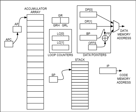
图1. MAXQ20内核的程序员模型包括16个通用累加器,两个循环计数器和一组数据指针。
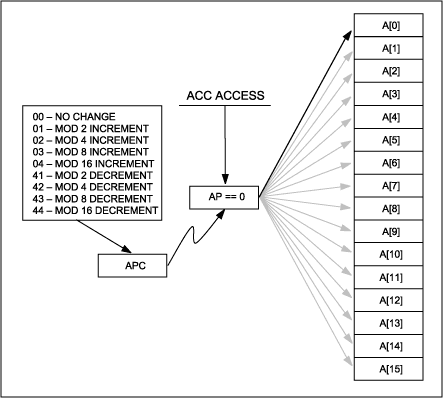
图2. 有效累加器通过AP寄存器指定,AP寄存器本身可通过累加器访问指令来修改。

图3. GR寄存器支持字节提取、字节交换以及16位符号扩展功能。
注意,数据存储器通过这三个数据指针之一进行寻址,与此不同,代码存储器通过指令指针寻址。尽管所有MAXQ处理器都包含存储器管理单元(MMU),允许将任意存储器片段作为代码或者数据来处理,但代码与数据总线是分离的。采用独立的总线来提取代码与数据是MAXQ20内核的基本特点,允许在一个时钟周期内同时访问代码和数据。
传送-触发技术能够以简单的MOVE指令完成CPU提供的各项功能。尽管MAXQ汇编器支持30条以上的指令操作码,我们可以采用以下方式对MAXQ指令集包含的每条指令进行编程:
执行一条MAXQ指令时,会将源寄存器的值或一个立即数载入目的寄存器。此外,这个数据传送操作还会触发其它事件,如递增或递减一个指针、设置某些状态位或者执行其它功能。因此,这种架构具有传送-触发特性。为实现这种架构,需要大量辅助寄存器的支持。在MAXQ20内核中,总计有512个寄存器地址,被划分为两大类:外设寄存器空间与系统寄存器空间(图4)。
前六个寄存器模块(模块0到5)专门用作外设寄存器;后九个模块(模块7到F)用作系统寄存器(模块6被保留)。尽管对应不同的MAXQ处理器类型其外设寄存器模块各不相同,但所有MAXQ处理器的系统寄存器配置是相同的(图5)。
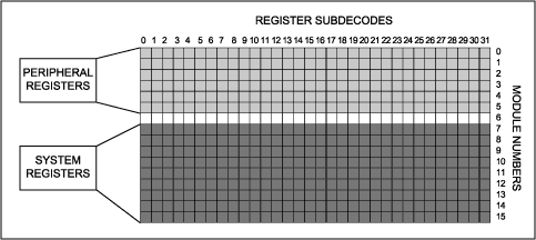
图4. MAXQ20内核中的寄存器划分为两大部分:寄存器组0到5是外设寄存器,不同的MAXQ器件会有所不同;寄存器组7到15是系统寄存器,在所有MAXQ器件中保持相对固定。
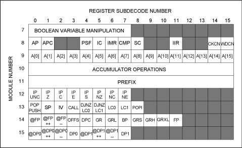
图5. MAXQ系统寄存器分配表,包括所有MAXQ20处理器共有的寄存器和用来执行指令集的附加寄存器。
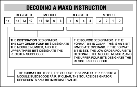
图6. 一条MAXQ指令包含三个部分:一个源标识符、一个目的标识符和一个用来指明源标识符是立即操作数还是寄存器操作数的源格式位。
以指令操作码0x0923为例,该指令的FORMAT位被清零,表示源标识符(23)应当被视作一个8位立即数来处理。目标模块是模块9,对应累加器阵列。该阵列中的寄存器0是累加器A[0]。所以,这条指令的作用是将值0x0023加载到寄存器A[0]。在本例当中,源标识符与目的标识符均不提供附加功能。
第二个例子可考虑操作码0xBF09。在这条指令中,FORMAT位被置为1,表示源标识符应当被看作是一个寄存器。上文已对模块9的寄存器0进行了分析:即表示累加器A[0]。在目的字段,模块F是数据指针模块,寄存器3 (指令中第12至14位)表示数据指针DP[0]。因此,这条指令将A[0]的内容传送至DP[0]中。
注意,在某些情况下寄存器模块中的个别位置并不一定对应实际的寄存器。或者,它们可以对应一个实际寄存器,但访问这个寄存器时会实现一些附加功能。举例来说,我们将前一个例子稍作修改,采用操作码0xAF09。只是目的寄存器模块中的寄存器子译码发生了变化。这条指令现在并不加载寄存器DP[0],而是使DP[0]递减,并将源数据存储到DP[0]所指向的新存储器位置。也就是说,这条指令执行了一个预先递减指针指向位置的间接存储操作。在MAXQ汇编器中,这可以按照@ DP[0], A[0]的形式进行编程,但也可以简单地编程为M15[2], M9[0]。
表1. 模块8功能
值得特别注意的是AP与APC寄存器。AP寄存器确定哪个累加寄存器是有效的,也就是说,它指定了执行算术、逻辑与位运算的目标寄存器。它可以指向阵列中的任意累加器。
APC寄存器包含了一组位,它们定义了累加器操作完成后AP寄存器是如何改变的。因此,AP寄存器能够以2的幂为模进行循环递增或递减,从而简化了多倍精度运算。
表2. 模块10作为源寄存器
如果源寄存器处于模块10,而目的寄存器处于模块10以外的任意模块,则累加器的内容被传送到目的寄存器。如果模块10的子译码值为0,则根据APC寄存器的位对AP寄存器进行修改;如果子译码值为1,则AP寄存器值不变。
注意,当前版本的宏汇编器并不支持子译码1。这是因为没有助记符或者修饰符表示子译码1。所以,指令move A[1], ACC生成的操作代码永远是0x990A,而绝不会是0x991A (表3)。
表3. 模块10作为目的寄存器
当模块10被指定为目的标识符,并且源标识符是一个立即数或者处于模块10以外的任意模块时,源信息会传送到ALU;目的信息通过ALU的输出来获取,而不是直接来自源信息。算术与逻辑指令就是通过这种方式完成操作的。
注意,对于源寄存器的表示方式并没有限制。它可以是一个立即数,一个间接存储器位置,甚至可以是堆栈中的数值或一个外设寄存器(表4)。
表4. 模块10既作为源寄存器、又作为目的寄存器
当源与目的标识符均为模块10时,它或者是一个纯累加器指令,或者是一个包含进位的位操作。在任何情况下,都使用源与目的寄存器来指示特定操作。
目的子译码0指定了所有的纯累加器指令,包括取补码、取反码以及所有移位、循环与交换指令。目的子译码1、2、3、6与7涵盖了按位加载与带进位操作。最终,目的子译码5实现纯进位操作:载入0和1与取补码。
注意,目的子译码5的一个源子译码为指定的NOP指令。在任何情况下,对于既无附加功能又访问空寄存器的操作都会视为NOP操作;MOVE M10[5], M10[3]命令特定用来保证在当前或将来的MAXQ器件中不执行操作。这条指令(0xDA3A)是所有当前汇编程序中的运行代码,用于NOP助记符。
模块12—指令指针
模块12的独特之处在于它包含了一些条件加载操作。如果模块12被用作源模块,只是简单地将IP复制到目的标识符。但如果模块12是目的模块,则除非满足指定的条件,否则不会执行任何操作(表5)。
表5. 模块12子译码
模块12还有一个独特之处,也就是当加载8位立即数源时,源数值被解释为一个有符号整型数,并加到指令指针中预先递增的数据上。这个加法操作使得相对短跳转更为简单,进而大大节省了代码尺寸。这也同样意味着任意短或长跳转指令都可以是有条件的。
这个模块仅仅支持指令指针寄存器(IP)的简单加载与存储。CALL指令被当作一个可同样加载IP的堆栈指令,而不是作为一个执行压栈的IP指令。因此,CALL指令的传送在堆栈指针模块(模块13)中实现。同样,不存在直接RET指令,它由POP IP所代替。
表6. 模块13子译码
子译码3、4和5用作IP寄存器的代理。将递增后的指令指针压栈之后,子译码3加载指令指针,从而实现一个传统的CALL指令。子译码4和5将指定的循环计数器递减后重新加载到循环计数器,并且如果预先递减的循环计数器不为零,则将源操作数也加载到指令指针中。载入目的子译码的源可以是任意形式,例如,指令DJNZ LC[0], A[1]完全有效,该指令会递减LC[0],当递减结果不为零时跳转至A[1]存储的地址位置。
表7. 模块14子译码
数据指针控制寄存器(DPC)说明了数据指针是如何发挥作用的。特别地,它为每一个数据指针提供了一个位,用来定义该指针是工作于字模式还是字节模式。它同样包含了一个字段,用于定义哪个指针是当前的源指针。这一点非常必要,因为当源指针被加载后,访问源时只有一条用于操作数的数据总线。
当需要按字节来访问16位数据时,使用GR寄存器就会很方便。只要GR装入了16位数据,就可以分别通过GRL和GRH寄存器提取低字节与高字节。GRS寄存器中包含GR数据字节交换后的结果;GRXL寄存器与GRL寄存器相同,区别仅在于它的高字节是低字节的符号扩展。
基址指针寄存器(BP)是MAXQ架构中三个数据存储器指针寄存器之一,并且只有它支持偏移量寄存器。BP通常指向数据结构的基址,8位无符号偏移寄存器指向该结构的某一个数据单元。注意,该寄存器的递增或递减操作仅仅会修改偏移寄存器,绝不会修改基址寄存器的内容。
表8. 模块15子译码
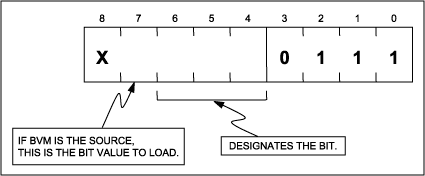
图7. 模块7的子译码指定了要提取或者替换的位,如果作为源标识符,则表示要加载的立即数位值。
作为目的标识符,BVM代理进位功能。源的一位数据被提取并复制到进位中。如果BVM是源标识符,子译码第3位(整个源标识符的第7位)的值将被复制到目的寄存器的指定位中。
需注意,BVM仅仅作用于外设寄存器的第0位至第7位。由于大多数外设寄存器(尤其是I/O端口)仅为8位长度,所以这种工作模式是可以接受的。但如果访问16位外设寄存器,只有低8位是可用的。
有几种解决方案来处理这种局限性,比如采用可变长度的指令和寄存器,并允许独立访问低字节和高字节(MAXQ中的GR寄存器就是这样一个例子)。但这些方案都不尽完美,因为它们使得译码逻辑变得非常复杂,或者需要引入新的寄存器(图8)。
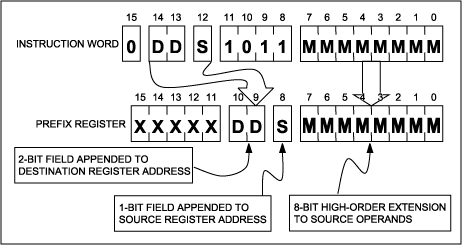
图8. 当前缀寄存器作为目的寄存器时,8位立即数源提供16位立即操作数的高字节;目的子译码则为源操作数和目的操作数提供附加位,以寻址每个模块当中的所有32个寄存器。
前缀机制从两方面改善了这一操作过程。首先,这种机制仅向那些需要附加位的特定指令添加前缀,从而节省了代码空间与执行时间。其次,由于既可为立即数又可为寄存器标识符提供附加位,该机制在扩展寄存器空间的同时又保持了整体架构的性能。
前面提到,尽管每一个寄存器模块都包含32个寄存器,但源寄存器只有4位标识符,目标寄存器只有3位标识符。前缀机制则可提供这些附加位。
前缀机制的鲜明特色表现为几个方面。首先,前缀指令中目的部分的特定位被用作立即数源位,用来访问子译码大于15的源地址寄存器,以及子译码大于7的目的地址寄存器。通过这种方式,单条前缀指令既能够访问任何寄存器或立即数,也能够访问任何寄存器子译码。
其次,前缀寄存器还有另一个独特之处,即它载入的任意值仅能够保持一个时钟周期。在此之后,该寄存器会自动清零。也就是说,必须在紧靠被前缀寄存器修改的指令之前,向前缀寄存器传送所需数据。这同样意味着前缀指令是不可中断的。如果紧随一个前缀操作之后发生了一次中断,则当中断返回主函数时前缀信息会丢失。
如图9所示,前缀寄存器中的位分别送至源标识符、目的标识符和立即数中。所以,尽管绝大多数指令可以在单周期内执行,以下指令仍然需要两个周期:寻址子译码大于7的目标寄存器;寻址子译码大于15的源寄存器;或者加载大于255的立即数。
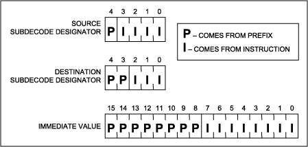
图9. 前缀寄存器可提供附加位,以实现16位立即操作数,以及寻址每个模块中所有32个源和目的寄存器。
为了说明这个过程,我们考虑指令move A[0], #010h。这条指令将一个立即数传送到模块9的寄存器0中,因此汇编器会生成如下的操作码:0910。但如果指令是A[10], #0320h的话,汇编器会自动地插入一条前缀指令:2B03 2920。
如果没有前缀指令,操作码2920会被解释为A[2], #020h。而前缀将一位添加到目的标识符,并将一些位添加到立即数中,从而允许处理器向任意寄存器子译码加载任意值,并且永远不会超过两个执行周期。
向量表中的最后一个入口地址用来重新初始化指针,并且任务调度器开始重新扫描向量表。
对于这个例子,假设该列表包含由标记、长度和数据串组成的数据对象。遍历该列表的程序如下:
打开APP阅读更多精彩内容
MAXQ处理器家族包括功能强大的8位、16位与32位单周期微控制器,能够在一个时钟周期内执行多个操作。本文探讨了MAXQ20内核的工作机制,并展示了其强劲性能。
程序模型
MAXQ20内核是一个16位CPU,这意味着所有的累加器以及大多数工作寄存器(堆栈、数据指针和计数器)均为16位长度。MAXQ20能够寻址64k字的代码空间(也就是64kB指令)与64k字(128kB)的数据空间(图1)。注意,对于一个基于MAXQ20内核的处理器来说,这些存储器空间大部分是空的。另外,由于固定用途ROM与数据RAM位于代码空间的高32kb内,访问这一区域的用户代码需要用到专门的内核特性,本文不讨论这一部分内容。

图1. MAXQ20内核的程序员模型包括16个通用累加器,两个循环计数器和一组数据指针。
累加器
十六个作为“累加器”的寄存器组成了一个通用寄存器阵列。累加器指针寄存器(AP)所指向的寄存器被指定为“有效累加器”,成为算术与逻辑运算的目标寄存器。因此,通过改变AP寄存器的值,这十六个寄存器当中的任意一个均可被指定为算术逻辑单元(ALU)的操作目标。无论何时访问有效累加器,均可通过累加器指针控制寄存器(APC)实现累加器指针AP的自动增减,从而简化多倍精度运算过程。在图2中,A[0]是有效累加器,但是任何累加器访问操作都可以使A[1]或者A[15]变为有效累加器,具体取决于APC寄存器的值。
图2. 有效累加器通过AP寄存器指定,AP寄存器本身可通过累加器访问指令来修改。
GR寄存器
通用寄存器(GR)有助于从16位字中提取单独字节。程序员可以使用GR将字节组装为一个字:低字节加载到GRL (通用寄存器-低字节)内,高字节加载到GRH (通用寄存器-高字节)内,然后可从GR中读取组装完毕的字。反过来,程序员也可以使用GR将一个字分解为两个字节。加载到GR的字可以在GRS (通用寄存器-字节交换)中以字节交换的形式读出。最后,通过读取GRXL (通用寄存器扩展低字节),可以将加载到GRL寄存器的字节扩展为有符号的字。参见图3。
图3. GR寄存器支持字节提取、字节交换以及16位符号扩展功能。
循环计数器
提供两个循环计数器:循环计数器0 (LC[0])与循环计数器1 (LC[1])。这些寄存器可以作为通用寄存器来使用,但主要用作循环计数器,从而在计数器值不为零时执行递减和跳转(DJNZ)操作。堆栈
MAXQ20内核具有一个专用的16级内部堆栈。一个堆栈指针指示下次使用的堆栈位置或者指示PUSH或CALL操作。数据存储器指针
MAXQ微控制器有三个访问数据存储器的指针。DP[0]和DP[1]是两个简单的16位指针。通过一个基址指针(BP)与一个8位无符号偏移量(OFFS)相加获得第三个指针。注意,数据存储器通过这三个数据指针之一进行寻址,与此不同,代码存储器通过指令指针寻址。尽管所有MAXQ处理器都包含存储器管理单元(MMU),允许将任意存储器片段作为代码或者数据来处理,但代码与数据总线是分离的。采用独立的总线来提取代码与数据是MAXQ20内核的基本特点,允许在一个时钟周期内同时访问代码和数据。
传送-触发架构
观察程序员模型,有些人会认为该架构采用传统的指令获取-译码单元实现装载指令、指令译码,随后激活CPU的特定单元。然而,这却是一个误区。MAXQ架构与其它较为传统的CPU相比,根本区别在于MAXQ内核的传送-触发特性。传送-触发技术能够以简单的MOVE指令完成CPU提供的各项功能。尽管MAXQ汇编器支持30条以上的指令操作码,我们可以采用以下方式对MAXQ指令集包含的每条指令进行编程:
        move Ma[b], Mc[d]
or
        move Ma[b], #immediate_value
其中,标识符Ma[b]指示寄存器模块a与寄存器子译码b。简而言之:包括ADD、位操作和寻址外部存储器在内的每一条指令,都可编程为两个寄存器之间的传送操作,或将立即数传送至寄存器的形式。执行一条MAXQ指令时,会将源寄存器的值或一个立即数载入目的寄存器。此外,这个数据传送操作还会触发其它事件,如递增或递减一个指针、设置某些状态位或者执行其它功能。因此,这种架构具有传送-触发特性。为实现这种架构,需要大量辅助寄存器的支持。在MAXQ20内核中,总计有512个寄存器地址,被划分为两大类:外设寄存器空间与系统寄存器空间(图4)。
前六个寄存器模块(模块0到5)专门用作外设寄存器;后九个模块(模块7到F)用作系统寄存器(模块6被保留)。尽管对应不同的MAXQ处理器类型其外设寄存器模块各不相同,但所有MAXQ处理器的系统寄存器配置是相同的(图5)。

图4. MAXQ20内核中的寄存器划分为两大部分:寄存器组0到5是外设寄存器,不同的MAXQ器件会有所不同;寄存器组7到15是系统寄存器,在所有MAXQ器件中保持相对固定。

图5. MAXQ系统寄存器分配表,包括所有MAXQ20处理器共有的寄存器和用来执行指令集的附加寄存器。
MAXQ指令译码
因为每条MAXQ指令实际上都是一个传送操作,每条指令都可划分为三个字段:源(SOURCE)指定数据从何处移出;目标(DESTINATION)指定数据传送到何处;格式位则指明源是一个立即数(FORMAT == 0),还是一个寄存器标示符(FORMAT == 1) (图6)。
图6. 一条MAXQ指令包含三个部分:一个源标识符、一个目的标识符和一个用来指明源标识符是立即操作数还是寄存器操作数的源格式位。
以指令操作码0x0923为例,该指令的FORMAT位被清零,表示源标识符(23)应当被视作一个8位立即数来处理。目标模块是模块9,对应累加器阵列。该阵列中的寄存器0是累加器A[0]。所以,这条指令的作用是将值0x0023加载到寄存器A[0]。在本例当中,源标识符与目的标识符均不提供附加功能。
第二个例子可考虑操作码0xBF09。在这条指令中,FORMAT位被置为1,表示源标识符应当被看作是一个寄存器。上文已对模块9的寄存器0进行了分析:即表示累加器A[0]。在目的字段,模块F是数据指针模块,寄存器3 (指令中第12至14位)表示数据指针DP[0]。因此,这条指令将A[0]的内容传送至DP[0]中。
注意,在某些情况下寄存器模块中的个别位置并不一定对应实际的寄存器。或者,它们可以对应一个实际寄存器,但访问这个寄存器时会实现一些附加功能。举例来说,我们将前一个例子稍作修改,采用操作码0xAF09。只是目的寄存器模块中的寄存器子译码发生了变化。这条指令现在并不加载寄存器DP[0],而是使DP[0]递减,并将源数据存储到DP[0]所指向的新存储器位置。也就是说,这条指令执行了一个预先递减指针指向位置的间接存储操作。在MAXQ汇编器中,这可以按照@ DP[0], A[0]的形式进行编程,但也可以简单地编程为M15[2], M9[0]。
前缀寄存器
每个模块包含32个寄存器,但只有四位用于选择源寄存器,三位用于指定目的寄存器。乍一看,这似乎意味着无法读取一半的源寄存器子译码,并且不能对四分之三的目的寄存器子译码进行写操作。幸好MAXQ的架构设计解决了这个问题。每一款MAXQ处理器都提供一个前缀寄存器,用来提供这些额外的寄存器地址位,并提供按字传送操作中的高字节数据。详细信息请参阅模块11—前缀一节。一次一个模块地创建MAXQ指令集
以下各节详细阐述了系统寄存器模块,以及它们如何相互作用以创建所有列出和未列出的指令。我们首先来研究MAXQ20内核的核心:累加器阵列。模块9—累加器
尽管大多数衍生器件只提供16个累加器,MAXQ架构可支持最多32个累加器。通过模块9直接访问这些累加器。该模块内每个寄存器代表一个累加器。从概念上讲,模块9是最简单的模块,但是还有两个模块会影响累加器阵列。模块8—系统控制
这个模块包含一些管理系统操作的寄存器,比如中断控制和程序状态标志位。其中的许多寄存器超出了本文的讨论范围,若需了解更多信息请参考器件规格资料。表1列出了一部分寄存器模块。表1. 模块8功能
| Sub | Function | S/D | Description |
| 0 | Accumulator Pointer Register | S/D | Designates the active accumulator, i.e., the accumulator that serves as the destination of ALU operations. |
| 1 | Accumulator Pointer Control Register | S/D | Tells the AP how to behave. For this discussion, it is a general-purpose 8-bit register. |
| 4 | Program Status Flags Register | S/D | Contains the flags (carry, zero, equal) that a user may wish to monitor in the main program. The register is usually used as a source, but can also serve as a destination. Note that some of the bits are read-only (e.g., the Z flag is the logical NOR of all the bits in the active accumulator). |
| 5 | Interrupt Control Register | S/D | Manages the interrupt subsystem. |
| 6 | Interrupt Mask Register | S/D | Typically contains bits that mask interrupts at the module level. |
| 7 | Comparator Register | DO | Write-only subdecode. Not really a register, since there is no actual memory behind it. When this subdecode is written, the Equal bit is set in the PSF if the source operand matches the contents of the current accumulator; otherwise, the Equal bit is cleared. |
| 8 | System Control Register | S/D | Contains bits that control aspects of system operation (read/write). |
| 11 | Interrupt Identification Register | SO | Contains a collection of bits that identify the source of an interrupt. |
| 14 | Clock Control Register | S/D | Contains bits pertaining to the system clock. In particular, controls the master clock divide ratio, as well as clock source if more than one source is present in the particular microcontroller. |
| 15 | Watchdog Control Register | S/D | Controls the operation of the watchdog timer. Most MAXQ parts contain a watchdog timer that can reset the processor if it becomes stuck in a program loop. |
值得特别注意的是AP与APC寄存器。AP寄存器确定哪个累加寄存器是有效的,也就是说,它指定了执行算术、逻辑与位运算的目标寄存器。它可以指向阵列中的任意累加器。
APC寄存器包含了一组位,它们定义了累加器操作完成后AP寄存器是如何改变的。因此,AP寄存器能够以2的幂为模进行循环递增或递减,从而简化了多倍精度运算。
模块10—累加器功能
累加器的大部分实际工作是在模块10中完成的。它能够访问传统ALU功能以及有效累加器的数据位。模块10非常独特,它在作为源寄存器、目的寄存器或者既作为源寄存器又作为目的寄存器的情况下有着不同的行为(表2)。表2. 模块10作为源寄存器
| Sub | Function | Description |
| 0 | Active Accumulator | The contents of the active accumulator are moved to the destination and the AP is changed according to the APC. |
| 1 | Active Accumulator | The contents of the active accumulator are moved to the destination and the AP is unchanged. |
如果源寄存器处于模块10,而目的寄存器处于模块10以外的任意模块,则累加器的内容被传送到目的寄存器。如果模块10的子译码值为0,则根据APC寄存器的位对AP寄存器进行修改;如果子译码值为1,则AP寄存器值不变。
注意,当前版本的宏汇编器并不支持子译码1。这是因为没有助记符或者修饰符表示子译码1。所以,指令move A[1], ACC生成的操作代码永远是0x990A,而绝不会是0x991A (表3)。
表3. 模块10作为目的寄存器
| Sub | Function | Description |
| 0 | MOVE | The source is moved to the accumulator. |
| 1 | AND | The contents of the source are logically ANDed with the accumulator. |
| 2 | OR | The contents of the source are logically ORed with the accumulator. |
| 3 | XOR | The contents of the source are logically exclusive-ORed with the accumulator. |
| 4 | ADD | The contents of the source are arithmetically added to the accumulator. Overflow out of the MSB sets the carry bit. |
| 5 | SUB | The contents of the source are arithmetically subtracted from the accumulator. Underflow sets the carry bit. |
| 6 | ADDC | The contents of the source and the carry bit are added to the accumulator. |
| 7 | SUBB | The contents of the source and the carry bit are subtracted from the accumulator. |
当模块10被指定为目的标识符,并且源标识符是一个立即数或者处于模块10以外的任意模块时,源信息会传送到ALU;目的信息通过ALU的输出来获取,而不是直接来自源信息。算术与逻辑指令就是通过这种方式完成操作的。
注意,对于源寄存器的表示方式并没有限制。它可以是一个立即数,一个间接存储器位置,甚至可以是堆栈中的数值或一个外设寄存器(表4)。
表4. 模块10既作为源寄存器、又作为目的寄存器
| Dest Sub | SRC Sub | Function | Description |
| 0 | 0 | MOVE | The contents of the accumulator are moved to the accumulator; logically, an NOP. However, the AP register can be changed. |
| 1 | CPL | The accumulator is complemented bitwise. | |
| 2 | SLA | The accumulator is shifted left one bit; low-order bit is set to zero. High-order bit is copied to carry. | |
| 3 | SLA2 | The accumulator is shifted left two bits; low-order two bits are set to zero. Bit 14 is copied to carry. | |
| 4 | RL | Accumulator is rotated left by one bit, with bit 15 copied to bit 0. Bit 15 is also copied to carry. | |
| 5 | RLC | Accumulator is rotated left by one bit, with bit 15 copied to carry and carry copied to bit 0. | |
| 6 | SLA4 | Accumulator is shifted left four bits; low-order four bits are set to zero. Bit 12 is copied to carry. | |
| 7 | XCHN | The nibbles in each byte of the accumulator are reversed; 0x1234 becomes 0x2143. | |
| 8 | XCH | The bytes of the accumulator are reversed; 0x1234 becomes 0x3412. | |
| 9 | NEG | The accumulator is arithmetically negated. | |
| 10 | SR | The accumulator is shifted right one bit. Bit 15 is loaded with zero. Bit 0 is moved to carry. | |
| 11 | SRA4 | Accumulator is shifted right four bits; high-order four bits are set to zero. Bit 3 is copied to carry. | |
| 12 | RR | Accumulator is rotated right by one bit, with bit 0 copied to bit 15. Bit 0 is also copied to carry. | |
| 13 | RRC | Accumulator is rotated right by one bit, with bit 0 copied to carry and carry copied to bit 15. | |
| 14 | SRA2 | The accumulator is shifted right two bits; high-order two bits are set to zero. Bit 1 copied to carry. | |
| 15 | SRA | The accumulator is shifted right one bit; high-order bit is set to zero. Low-order bit copied to carry. | |
| 1 | Bit | AND C | The carry bit is logically ANDed with the designated bit in the accumulator. |
| 2 | Bit | OR C | The carry bit is logically ORed with the designated bit in the accumulator. |
| 3 | Bit | XOR C | The carry bit is logically XORed with the designated bit in the accumulator. |
| 5 | 0 | C ← 0 | The carry bit is set to zero. |
| 1 | C ← 1 | The carry bit is set to one. | |
| 2 | C ← C | The carry bit is complemented. | |
| 3 | NOP | Guaranteed NOP | |
| 6 | Bit | C ← ACC | The designated bit in the accumulator is loaded into carry. |
| 7 | Bit | ACC ← C | Carry is loaded into the designated bit in the accumulator. |
当源与目的标识符均为模块10时,它或者是一个纯累加器指令,或者是一个包含进位的位操作。在任何情况下,都使用源与目的寄存器来指示特定操作。
目的子译码0指定了所有的纯累加器指令,包括取补码、取反码以及所有移位、循环与交换指令。目的子译码1、2、3、6与7涵盖了按位加载与带进位操作。最终,目的子译码5实现纯进位操作:载入0和1与取补码。
注意,目的子译码5的一个源子译码为指定的NOP指令。在任何情况下,对于既无附加功能又访问空寄存器的操作都会视为NOP操作;MOVE M10[5], M10[3]命令特定用来保证在当前或将来的MAXQ器件中不执行操作。这条指令(0xDA3A)是所有当前汇编程序中的运行代码,用于NOP助记符。
模块12—指令指针
模块12的独特之处在于它包含了一些条件加载操作。如果模块12被用作源模块,只是简单地将IP复制到目的标识符。但如果模块12是目的模块,则除非满足指定的条件,否则不会执行任何操作(表5)。
表5. 模块12子译码
| Sub | Description |
| 0 | If source, load the destination from IP. If destination, load IP from the source. |
| 1 | If source, load the destination from IP. If destination, load IP from source only if ACC == 0. |
| 2 | If source, load the destination from IP. If destination, load IP from source only if C == 1. |
| 3 | If source, load the destination from IP. If destination, load IP from source only if the most recent CMP instruction set the EQ flag. |
| 4 | If source, load the destination from IP. If destination, load IP from source only if the high-order bit of the accumulator is set. |
| 5 | If source, load the destination from IP. If destination, load IP from source only if ACC == 0. |
| 6 | If source, load the destination from IP. If destination, load IP from source only if C == 0. |
| 7 | If source, load the destination from IP. If destination, load IP from source only if the most recent CMP instruction cleared the EQ flag. |
模块12还有一个独特之处,也就是当加载8位立即数源时,源数值被解释为一个有符号整型数,并加到指令指针中预先递增的数据上。这个加法操作使得相对短跳转更为简单,进而大大节省了代码尺寸。这也同样意味着任意短或长跳转指令都可以是有条件的。
这个模块仅仅支持指令指针寄存器(IP)的简单加载与存储。CALL指令被当作一个可同样加载IP的堆栈指令,而不是作为一个执行压栈的IP指令。因此,CALL指令的传送在堆栈指针模块(模块13)中实现。同样,不存在直接RET指令,它由POP IP所代替。
模块13—堆栈指针
模块13不仅包含与堆栈指针相关的寄存器,还包含循环计数器与中断向量。注意,部分子译码仅仅作为目的时有效。子译码8只在作为源时才有效(表6)。表6. 模块13子译码
| Sub | Function | S/D | Description |
| 0 | PUSH/POP | S/D | If the destination, increment the stack pointer and store the source operand on the stack. If the source, load the value on the stack to the destination and decrement the stack pointer. |
| 1 | Stack Pointer | S/D | Points to the most recently used location on the internal dedicated stack. |
| 2 | Interrupt Vector | S/D | Points to the location in program memory where the interrupt service routine resides. |
| 3 | CALL | DO | Pushes the current IP to the stack, then loads IP from the source operand. Will cause unpredictable results if used as a source operand. |
| 4 | DJNZ LC[0] | DO | Decrements LC[0] and loads IP with the source IF LC[0] != 0. Will cause unpredictable results if used as a source operand. |
| 5 | DJNZ LC[1] | DO | Decrements LC[1] and loads IP with the source IF LC[1] != 0. Will cause unpredictable results if used as a source operand. |
| 6 | LC[0] | S/D | Data is moved to/from loop counter 0. |
| 7 | LC[1] | S/D | Data is moved to/from loop counter 1. |
| 8 | POPI | SO | The value on the stack is copied to the destination, the stack point is decremented, and the IN SERVICE bit is cleared. Primarily used to implement a RETI operation. |
子译码3、4和5用作IP寄存器的代理。将递增后的指令指针压栈之后,子译码3加载指令指针,从而实现一个传统的CALL指令。子译码4和5将指定的循环计数器递减后重新加载到循环计数器,并且如果预先递减的循环计数器不为零,则将源操作数也加载到指令指针中。载入目的子译码的源可以是任意形式,例如,指令DJNZ LC[0], A[1]完全有效,该指令会递减LC[0],当递减结果不为零时跳转至A[1]存储的地址位置。
模块14—GR、BP和DPC
模块14包含DPC寄存器、GR寄存器和全部与基址指针和偏移寄存器相关的寄存器(表7)。表7. 模块14子译码
| Sub | Function | S/D | Description |
| 0 | @BP[offs] | S/D | Reads or writes the data memory location pointed to by BP+offs |
| 1 | @BP[offs++] | S/D | If source, reads the data memory location pointed to by BP+offs and then increments offs. If destination, increments offs and then stores the source data at BP+offs. |
| 2 | @BP[offs--] | S/D | If source, reads the data memory location pointed to by BP+offs and then decrements offs. If destination, decrements offs and then stores the source data at BP+offs. |
| 3 | offs | S/D | The 8-bit offset register |
| 4 | DPC | S/D | The data pointer control register defines which data pointer is the current source pointer and the word/byte status of each data pointer. |
| 5 | GR | S/D | The 16-bit general register |
| 6 | GRL | S/D | The low-order byte of the 16-bit general register |
| 7 | BP | S/D | The 16-bit base memory pointer |
| 8 | GRS | SO | The byte-swapped version of the GR |
| 9 | GRH | S/D | The high-order byte of the 16-bit general register |
| 10 | GRXL | SO | The sign-extended low byte of the GR |
| 11 | BP[offs] | SO | The sum of the base pointer and the offset |
数据指针控制寄存器(DPC)说明了数据指针是如何发挥作用的。特别地,它为每一个数据指针提供了一个位,用来定义该指针是工作于字模式还是字节模式。它同样包含了一个字段,用于定义哪个指针是当前的源指针。这一点非常必要,因为当源指针被加载后,访问源时只有一条用于操作数的数据总线。
当需要按字节来访问16位数据时,使用GR寄存器就会很方便。只要GR装入了16位数据,就可以分别通过GRL和GRH寄存器提取低字节与高字节。GRS寄存器中包含GR数据字节交换后的结果;GRXL寄存器与GRL寄存器相同,区别仅在于它的高字节是低字节的符号扩展。
基址指针寄存器(BP)是MAXQ架构中三个数据存储器指针寄存器之一,并且只有它支持偏移量寄存器。BP通常指向数据结构的基址,8位无符号偏移寄存器指向该结构的某一个数据单元。注意,该寄存器的递增或递减操作仅仅会修改偏移寄存器,绝不会修改基址寄存器的内容。
模块15—数据指针
模块15包含了MAXQ架构中三个数据指针中的两个。根据子译码的不同,访问这个模块将执行一个直接或间接加载,或者存储操作,并可能在间接访问后递增或递减数据指针。这些寄存器子译码既可以用作源寄存器又可以用作目的寄存器(表8)。表8. 模块15子译码
| Sub | Function | Description |
| 0 | @DP[0] | Reads or writes the data memory location pointed to by DP[0]. |
| 1 | @DP[0]++ | If source, reads the data memory location pointed to by DP[0] and then increments DP[0]. If destination, increments DP[0] and then stores the source data at DP[0]. |
| 2 | @DP[0]-- | If source, reads the data memory location pointed to by DP[0] and then decrements DP[0]. If destination, decrements DP[0] and then stores the source data at DP[0]. |
| 3 | DP[0] | Data pointer 0 |
| 4 | @DP[1] | Reads or writes the data memory location pointed to by DP[1] |
| 5 | @DP[1]++ | If source, reads the data memory location pointed to by DP[1] and then increments DP[1]. If destination, increments DP[1] and then stores the source data at DP[1]. |
| 6 | @DP[1]-- | If source, reads the data memory location pointed to by DP[1] and then decrements DP[1]. If destination, decrements DP[1]. and then stores the source data at DP[1]. |
| 7 | DP[1] | Data pointer 1 |
模块7—布尔变量操作
借助布尔变量操作(BVM)模块(模块7),允许对典型MAXQ处理器中的许多寄存器进行按位提取和置位/清零(图7)操作。需要注意,并不是所有模块均与BVM模块连接。通常情况下,只有外设模块会与BVM相连;系统寄存器则不会。因此,在BVM与系统寄存器之间传送数据可能产生不可预料的结果。
图7. 模块7的子译码指定了要提取或者替换的位,如果作为源标识符,则表示要加载的立即数位值。
作为目的标识符,BVM代理进位功能。源的一位数据被提取并复制到进位中。如果BVM是源标识符,子译码第3位(整个源标识符的第7位)的值将被复制到目的寄存器的指定位中。
需注意,BVM仅仅作用于外设寄存器的第0位至第7位。由于大多数外设寄存器(尤其是I/O端口)仅为8位长度,所以这种工作模式是可以接受的。但如果访问16位外设寄存器,只有低8位是可用的。
模块11—前缀
前缀模块是MAXQ架构独有的特性,它解决了所有16位微控制器共同面临的局限性。由于采用16位寄存器,立即数载入指令需要一个16位的操作数,这意味着一个有效的立即数载入指令需要多于16位的代码。有几种解决方案来处理这种局限性,比如采用可变长度的指令和寄存器,并允许独立访问低字节和高字节(MAXQ中的GR寄存器就是这样一个例子)。但这些方案都不尽完美,因为它们使得译码逻辑变得非常复杂,或者需要引入新的寄存器(图8)。

图8. 当前缀寄存器作为目的寄存器时,8位立即数源提供16位立即操作数的高字节;目的子译码则为源操作数和目的操作数提供附加位,以寻址每个模块当中的所有32个寄存器。
前缀机制从两方面改善了这一操作过程。首先,这种机制仅向那些需要附加位的特定指令添加前缀,从而节省了代码空间与执行时间。其次,由于既可为立即数又可为寄存器标识符提供附加位,该机制在扩展寄存器空间的同时又保持了整体架构的性能。
前面提到,尽管每一个寄存器模块都包含32个寄存器,但源寄存器只有4位标识符,目标寄存器只有3位标识符。前缀机制则可提供这些附加位。
前缀机制的鲜明特色表现为几个方面。首先,前缀指令中目的部分的特定位被用作立即数源位,用来访问子译码大于15的源地址寄存器,以及子译码大于7的目的地址寄存器。通过这种方式,单条前缀指令既能够访问任何寄存器或立即数,也能够访问任何寄存器子译码。
其次,前缀寄存器还有另一个独特之处,即它载入的任意值仅能够保持一个时钟周期。在此之后,该寄存器会自动清零。也就是说,必须在紧靠被前缀寄存器修改的指令之前,向前缀寄存器传送所需数据。这同样意味着前缀指令是不可中断的。如果紧随一个前缀操作之后发生了一次中断,则当中断返回主函数时前缀信息会丢失。
如图9所示,前缀寄存器中的位分别送至源标识符、目的标识符和立即数中。所以,尽管绝大多数指令可以在单周期内执行,以下指令仍然需要两个周期:寻址子译码大于7的目标寄存器;寻址子译码大于15的源寄存器;或者加载大于255的立即数。

图9. 前缀寄存器可提供附加位,以实现16位立即操作数,以及寻址每个模块中所有32个源和目的寄存器。
为了说明这个过程,我们考虑指令move A[0], #010h。这条指令将一个立即数传送到模块9的寄存器0中,因此汇编器会生成如下的操作码:0910。但如果指令是A[10], #0320h的话,汇编器会自动地插入一条前缀指令:2B03 2920。
如果没有前缀指令,操作码2920会被解释为A[2], #020h。而前缀将一位添加到目的标识符,并将一些位添加到立即数中,从而允许处理器向任意寄存器子译码加载任意值,并且永远不会超过两个执行周期。
实例
独特的MAXQ20内核结构可以实现一些其它处理器不能完成的操作。向量中断
MAXQ20内核仅具有一个中断向量寄存器,一些用户可能认为这是一个缺陷。但实际情况是:考虑到具有两个外部中断的系统,可将其中的设备A连接至端口0位0,设备B连接至端口0位1;对应的中断选择可以像跳转PIO一样操作简单。在地址0上,编码为: 0000: IRET
0001: jump SERVICE_DEVICE_A
0002: jump SERVICE_DEVICE_B
0003: jump SERVICE_DEVICE_A
该例中,设备A具有中断服务优先权。也就是说,如果两个中断请求线同时有效(端口0上位0和位1均有效),先响应设备A。在中断服务程序结束时,只有当设备A中断不再有效时,才能够响应设备B中断。任务管理器
在多数应用程序中,轮询任务列表非常重要,以便产生一个多任务处理环境下的原始数据类型。这点在无需优先权限时非常有用(或不需要实时操作的情况)。MAXQ结构简化了这种程序:task_wheel_init:
move dp[0], #task_list
task_wheel:
move dp[0], dp[0]
jump @dp[0]++
.
.
.
task_list:
dw task_01
dw task_02
dw task_03
dw task_wheel_init
在该例子中,DP[0]指向任务列表。在task_wheel程序中,DP[0]被选中用来作为源指针,并接着从任务列表中加载指令指针。每当完成一个任务时,不是执行一个RET,而是简单地跳转至task_wheel程序即可。向量表中的最后一个入口地址用来重新初始化指针,并且任务调度器开始重新扫描向量表。
遍历列表
通常,为做好标记的入口快速搜索非标准大小的对象是非常有用的。但对于某些处理器结构来说实现此功能是有困难的,因为其存储器访问功能已从ALU删除。在MAXQ中,这是一个非常简单的任务。| TAG | LEN | Data | |||||||||||||
| 3F | 09 | 00 | 01 | 02 | 03 | 04 | 05 | 06 | 07 | 08 | |||||
| 17 | 0E | 10 | 11 | 12 | 13 | 14 | 15 | 16 | 17 | 18 | 19 | 1A | 1B | 1C | 1D |
| 35 | 07 | 20 | 21 | 21 | 22 | 23 | 24 | 25 | |||||||
对于这个例子,假设该列表包含由标记、长度和数据串组成的数据对象。遍历该列表的程序如下:
item_seek:
        move acc, @dp[0]++     ;Get tag
        jump z, item_not_found ;Tag==0 means end of list
        cmp  a[1]              ;A[1] has target tag
        jump e, item_found     ;If item==target, exit
        move acc, @dp[0]++     ;If no match, get data len
        add  dp[0]             ;Add to pointer
        move dp[0], acc        ;Store pointer back
        jump item_seek         ;...and seek next item.
该程序8个指令遍历列表,寻找匹配项或标记为零的项,以此来终止列表。采用8MHz MAXQ20内核时,该程序每秒遍历一百万次。结论
尽管MAXQ的内核看起来比较简单,但是传送-触发架构使得它在速度与灵活性方面具有突出的优势。由于通过寄存器接口直接寻址外设,嵌入式外设的数据传送速度极快。总的来说,MAXQ内核在任何方面都是大多数微控制器应用的上佳选择。
声明:本文内容及配图由入驻作者撰写或者入驻合作网站授权转载。文章观点仅代表作者本人,不代表电子发烧友网立场。文章及其配图仅供工程师学习之用,如有内容侵权或者其他违规问题,请联系本站处理。
举报投诉
- 相关推荐
- 热点推荐
- MAXQ1061
-
MAXQ1065EVKIT: Evaluation Kit for the MAXQ1065 Data Sheet MAXQ1065EVKIT: Evaluation Kit for the MAXQ1065 Data Sheet2023-10-17 32
-
MAXQ3120电表参考设计的定制功能是什么2021-05-12 884
-
USB收发器的微控制电路MAXQ612相关资料下载2021-04-19 1291
-
MAXQ8913芯片结束资料分享2012-09-28 1987
-
MAXQ612/MAXQ622低功耗、16位MAXQ微控制器2011-05-28 1662
-
揭密数字可编程电位计技术2011-02-12 3455
-
MAXQ1850评估套件(EV kit)和面向MAXQ30的CrossWorks编译器的设计方案2010-12-24 3966
-
基于MAXQ3180/MAXQ3183的电能表参考设计2010-10-28 1879
-
浦科特大揭密-PlexUTILITIES应用2010-03-27 2427
-
MAXQ612, MAXQ622 具有红外模块和USB (可2010-03-03 961
-
DVD光盘造假骗术大揭密2010-01-12 1711
-
MAXQ610 16-Bit MAXQ® Micro2009-02-06 1414
-
MAXQ7665,MAXQ7665A, MAXQ7665B2009-01-22 747
-
MAXQ610 pdf,MAXQ610 datasheet2008-10-10 643
全部0条评论

快来发表一下你的评论吧 !

