
NRZ码应用-NRZ Applications
通信设计应用
描述
This application note applies to following single-chip transceivers: (T1) DS21352, DS21552, DS21Q352, and DS21Q552; (E1) DS21354, DS21554, DS21Q354, and DS21Q554; and (combination) DS2155, DS2156, DS21Q55, and DS21Q56.
Overview
The line interface unit (LIU) can be completely decoupled from the framer/formatter to interface to optical, HDSL, or other devices with an NRZ interface. It can then be used to corrupt data, insert framing errors, or insert CRC errors, etc.
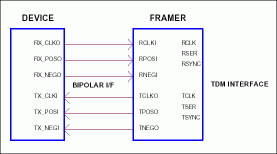
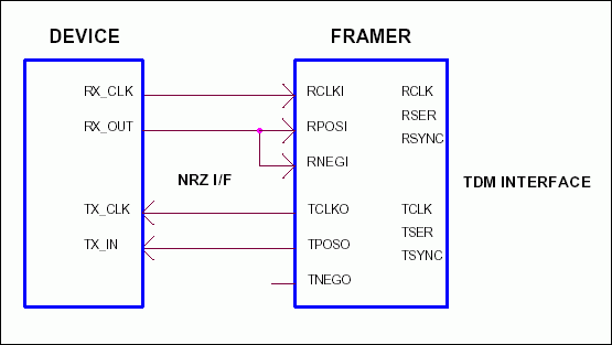
The framer/formatter can generate/detect either bipolar or NRZ data format (determined by the ODF bit). Table 1 shows the register settings for the output data format. Figures 1 and 2 show how to interface the framer/formatter to devices with bipolar or NRZ data modes.
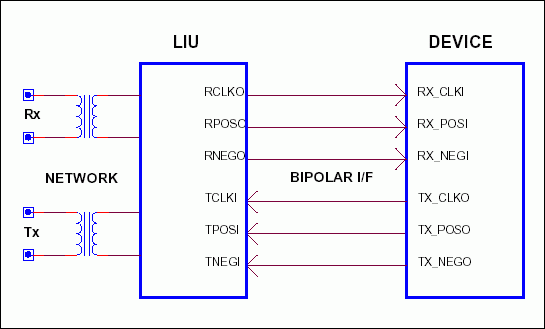
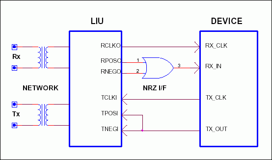
When the LIU receive side is interfaced to a device with NRZ data format, an OR-gate must be added to convert the bipolar data format into NRZ. See Figures 3 and 4 for both data mode applications.
Table 1. Output data format (ODF) regsiter settings
DS21352/552/Q352/Q552
CCR1: Common Control Register 1 (Address = 37 Hex)
| TESE | ODF | RSAO | TSCLKM | RSCLKM | RESE | PLB | FLB | FUNCTION |
| X | 0 | X | X | X | X | X | X | Bipolar data |
| X | 1 | X | X | X | X | X | X | NRZ data |
DS21354/554/Q354/Q554
TCR1: Transmit Control Register 1 (Address = 12 Hex)
| ODF | TFPT | T16S | TUA1 | TSiS | TSA1 | TSM | TSIO | FUNCTION |
| 0 | X | X | X | X | X | X | X | Bipolar data |
| 1 | X | X | X | X | X | X | X | NRZ data |
DS2155/56/Q55/Q56
IOCR1: I/O Configuration Register 1 (Address = 01 Hex)
| RSMS | RSMS2 | RSMS1 | RSIO | TSDW | TSM | TSIO | ODF | FUNCTION |
| X | X | X | X | X | X | X | 0 | Bipolar data |
| X | X | X | X | X | X | X | 1 | NRZ data |
The DS2155/56 provides a software control bit to separate or connect the LIU/framer when the LIUC pin is hardwired high. If the LIUC pin is connected low, then the LIUC bit has no effect (Table 2).
DS2155/56/Q55/Q56
LBCR: Loopback Control Register (Address = 4A Hex)
| -- | -- | -- | LIUC | LLB | RLB | PLB | FLB | FUNCTION |
| X | X | X | 0 | X | X | X | 0 | LIUC control |
Table 2. LIU mux control
| LIUC PIN | LIUC BIT | FUNCTION |
| 0 | 0 | LIU and framer separated |
| 0 | 1 | LIU and framer separated |
| 1 | 0 | LIU and framer connected |
| 1 | 1 | LIU and framer separated |

Figure 1. Framer connection to bipolar mode device.

Figure 2. Framer connection to NRZ mode device.

Figure 3. LIU connection to bipolar device.

Figure 4. LIU connection to NRZ mode device.
- 相关推荐
- 热点推荐
- NRZ
-
请问DAC38J82如何开启NRZ输出模式?2024-11-25 384
-
实现10GHz信号的NRZ-RZ转换,请问应该选择的器件/模块型号是什么呢?2018-08-10 2570
-
如何在Spartan3中将NRZ-单极(即(0,1))中的序列数据转换为NRZ-双极性?2019-10-28 1189
-
PAM4和NRZ信号的区别是什么2021-03-11 15746
-
关于200G NRZ光模块选择(推荐收藏)2021-06-03 1838
-
PAM-4信令取代NRZ有哪些优势?2021-06-17 2882
-
如何去分析把NRZ信号变为一个GSG信号可以回归共模信号的电路?2021-06-25 2178
-
NRZ-HDB3码转换器的高速长距离通信设计2009-04-15 621
-
NRZ-HDB3码转换器的高速长距离通信2006-03-11 3061
-
NRZ Applications2009-04-20 1463
-
不归零码(NRZ),不归零码(NRZ)是什么意思2010-03-17 28259
-
NRZ测试码型的频谱成分2012-03-07 3095
-
NRZ码的应用资料下载2017-04-12 1480
-
关于NRZ与PAM4信号差异2020-07-02 36415
-
pam4和nrz区别2023-12-29 9471
全部0条评论

快来发表一下你的评论吧 !

