
DS2153, DS2154 Selectable 120
通信设计应用
65人已加入
描述
Abstract: Different values of resistor can be selected between DS2153 or DS2154 single chip transceiver (SCT) and the transformer when interfacing to the E1 line with secondary overvoltage protection or in a high return loss configuration.
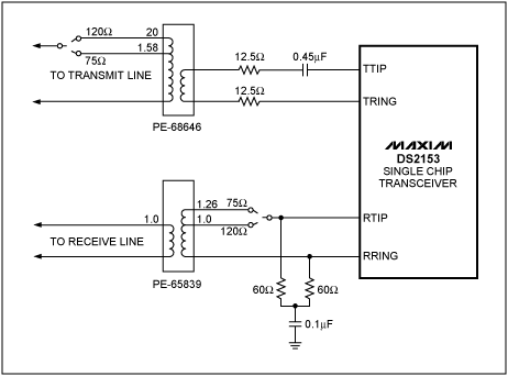
When interfacing to the E1 line with Secondary Over Voltage protection or in a high return loss configuration, resistors are added between the DS2153 outputs and the transformer. Normally the resistors are of different values depending on whether the interface is driving a 75Ω coax or 120Ω twisted wire pair line. Also a change in the termination resistor is required. A single set of resistors can be utilized in both situations by using the circuit shown in Figure 1. The dotted lines indicate jumper positions for selecting 75Ω or 120Ω operation.

Figure 1. E1 interface.
Table 1. Line Interface Control Register Settings
打开APP阅读更多精彩内容
When interfacing to the E1 line with Secondary Over Voltage protection or in a high return loss configuration, resistors are added between the DS2153 outputs and the transformer. Normally the resistors are of different values depending on whether the interface is driving a 75Ω coax or 120Ω twisted wire pair line. Also a change in the termination resistor is required. A single set of resistors can be utilized in both situations by using the circuit shown in Figure 1. The dotted lines indicate jumper positions for selecting 75Ω or 120Ω operation.

Figure 1. E1 interface.
Table 1. Line Interface Control Register Settings
| Line Type | L2 | L1 | L0 |
| 75Ω | 0 | 1 | 0 |
| 120Ω | 0 | 1 | 0 |
Notes:
- Transformers shown are available from Pulse.
- Resistors shown are within 1" of best value.
声明:本文内容及配图由入驻作者撰写或者入驻合作网站授权转载。文章观点仅代表作者本人,不代表电子发烧友网立场。文章及其配图仅供工程师学习之用,如有内容侵权或者其他违规问题,请联系本站处理。
举报投诉
- 相关推荐
- 热点推荐
- Interface
-
DS2153和DS2154的一般网络接口设计标准2023-01-13 1565
-
ds2154数据手册2016-12-26 613
-
DS2151,DS2153连接的ADSP-2181-DS212009-04-29 979
-
DS2154L vs. DS2153Q2009-04-20 1145
全部0条评论

快来发表一下你的评论吧 !

