
Step-Up Supply Charges Battery
电源新闻
20人已加入
描述
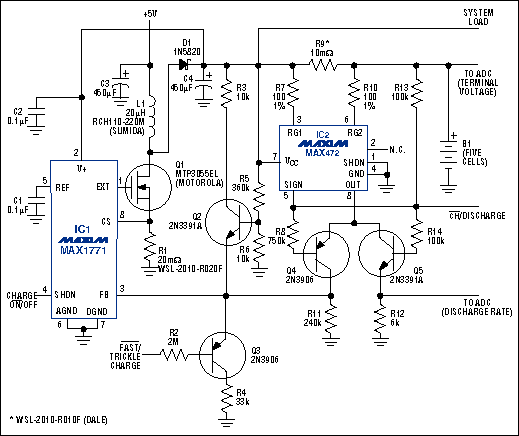
The circuit of Figure 1 supports the many portable applications in which a microprocessor (µP) or microcontroller (µC) controls charging of the battery. IC1 is a step-up switching regulator that boosts VIN (nominally 5V) as necessary to supply the combination of charging current and load current. The 5V source must include short-circuit protection. IC2 is a high-side current-sense amplifier that monitors the charging current. Commands from the processor include CHARGE active-low ON/OFF and active-low FAST/TRICKLE CHARGE.

Figure 1. This circuit controls charging of the battery while delivering current to the system load.
IC2 produces an output current (OUT) equal to 10-4 of the current through sense resistor R9. Q3 and Q4 are on during a fast-charge operation, so this output current flows through the parallel combination of R11 and (approximately) R4. The resulting feedback to IC1 (pin 3) maintains the fast-charge current through R9 at 500mA. This feedback also enables the regulator to supply as much as 500mA of load current in addition to the fixed 500mA of charging current. Q2 limits the battery voltage to 10V (2V/cell).
During the fast charge, an external processor and multi-channel A/D converter (ADC) must monitor the battery's terminal voltage. When the ADC senses a change of slope in this voltage, the processor terminates the fast charge by asserting a high on active-low FAST/ TRICKLE CHARGE. Q3 turns off, causing a rise in the feedback (FB) that lowers the charging current to the trickle-charge rate (approximately 60mA).
If IC1 shuts down, or if load current plus charging current exceeds the capability of IC1, the R9 current reverses as current flows out of the battery. IC2 indicates the reversal by allowing R13 to pull its open-collector SIGN output high, turning off Q4 and turning on Q5. Current through R12 then produces a voltage proportional to the battery's discharge current (5A through R9 produces a full-scale response of 3V across R12).
By integrating this voltage over time (sampling at fixed intervals and multiplying by the time interval), the A/D-processor system can monitor energy removed from the battery. Based on this measurement and the terminal-voltage measurement, the processor can then re-initiate a fast charge (by asserting active-low FAST/TRICKLE CHARGE low) before the battery reaches its end of life.
A related idea appeared in the 6/8/95 issue of EDN.
打开APP阅读更多精彩内容

Figure 1. This circuit controls charging of the battery while delivering current to the system load.
IC2 produces an output current (OUT) equal to 10-4 of the current through sense resistor R9. Q3 and Q4 are on during a fast-charge operation, so this output current flows through the parallel combination of R11 and (approximately) R4. The resulting feedback to IC1 (pin 3) maintains the fast-charge current through R9 at 500mA. This feedback also enables the regulator to supply as much as 500mA of load current in addition to the fixed 500mA of charging current. Q2 limits the battery voltage to 10V (2V/cell).
During the fast charge, an external processor and multi-channel A/D converter (ADC) must monitor the battery's terminal voltage. When the ADC senses a change of slope in this voltage, the processor terminates the fast charge by asserting a high on active-low FAST/ TRICKLE CHARGE. Q3 turns off, causing a rise in the feedback (FB) that lowers the charging current to the trickle-charge rate (approximately 60mA).
If IC1 shuts down, or if load current plus charging current exceeds the capability of IC1, the R9 current reverses as current flows out of the battery. IC2 indicates the reversal by allowing R13 to pull its open-collector SIGN output high, turning off Q4 and turning on Q5. Current through R12 then produces a voltage proportional to the battery's discharge current (5A through R9 produces a full-scale response of 3V across R12).
By integrating this voltage over time (sampling at fixed intervals and multiplying by the time interval), the A/D-processor system can monitor energy removed from the battery. Based on this measurement and the terminal-voltage measurement, the processor can then re-initiate a fast charge (by asserting active-low FAST/TRICKLE CHARGE low) before the battery reaches its end of life.
A related idea appeared in the 6/8/95 issue of EDN.
声明:本文内容及配图由入驻作者撰写或者入驻合作网站授权转载。文章观点仅代表作者本人,不代表电子发烧友网立场。文章及其配图仅供工程师学习之用,如有内容侵权或者其他违规问题,请联系本站处理。
举报投诉
-
AME5138 pdf datasheet (step-up2008-12-01 501
-
MAX1817 pdf datasheet (Step-Up2009-01-11 708
-
max1703 pdf datasheet (Step-Up2009-01-12 762
-
MAX1771 pdf datasheet (step-up switching controller)2009-02-22 1595
-
ZD1937,pdf datasheet (Step-Up2009-08-27 974
-
LM3311,pdf datasheet (Step-Up2009-09-08 1120
-
AP1603,pdf,datasheet (Step-Up2009-10-19 1037
-
AX5201 Step-up PWM DC DC Conve2009-12-08 862
-
UC2577-ADJ,pdf(Simple Step-Up2010-10-02 834
-
LT3782 - 2-Phase Step-Up DC/DC2008-09-01 1572
-
Step-up Converter with LDO Bea2009-05-04 2977
-
MAX17106 Step-Up Regulator and2009-08-26 1037
-
MAX8969,Step-Up Converter for Handheld Applications2011-12-22 964
-
几款直流升压电路,DC step-up circuit2018-09-20 2451
-
用1.8V供电可输出5V的升压电路(TPS60109升压电源),TPS60109 step-up power supply2019-02-09 6669
全部0条评论

快来发表一下你的评论吧 !

