
One-Hour Battery Charger Has S
电源新闻
20人已加入
描述
Because battery charges control power, they resemble regulators in some respects. Linear chargers, for example, are less efficient than switching types when operating at high current and a large VIN - VOUT difference. A linear charger, powered by a 15V car battery and delivering 2A while charging an 8V, 6-cell NiCd stack must dissipate 14 watts. Efficient chargers therfore employ switch-mode DC-DC conversion for deriving battery-charge voltage from VIN.
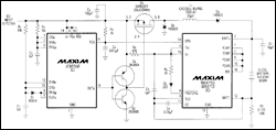
An efficient fast-charge circuit (Figure 1) features a controller chip that normally implements linear regulation with an external pnp transistor. This circuit, however, substitutes a p-channel MOSFET for the pnp and implements switch-mode PWM regulation with the help of an inductor, two Schottky diodes, and a 60¢ dual timer (IC1). The timer's "B" side is configured as a one-shot that receives nominal 70kHz triggers from the free-running "A" side.

More Detailed Image (PDF, 231kB)
Figure 1. This two-IC circuit provides efficient charging at a two-ampere rate for series connections of NiCd or NiMH cells.
During a charge, IC2 monitors the slope of battery voltage vs. time. The MAX712 (for nickel-metal-hydride batteries) terminates charging when the slope reaches zero; the MAX713 (for NiCD batteries) terminates charging when the slope goes negative. As a backup probision, you can program an internal timer to terminate charge after 1/4, 1/2, 1, or 2 hours (times a multiple of 1.5X or 2X).
As a further backup, comparator circuits in IC2 monitor the battery temperature, preventing charging if the battery is too cold and terminating charging if the battery becomes too hot. In every case, the IC applies a trickle charge of C/16 (125mA in Figure 1) after termination of the fast charge.
You can program IC2 for charging 1 to 16 cells in series. The device simultaneously monitors and regulates battery voltage and charge current (via current-sense resistor R6), and issues drive signals at the open-drain output DVR. These signals implement pulse-width modulation by altering the duty cycle of Q1's gate drive.
Constructed with narrow-SO surface-mount components, the circuit fits easily into notebook computers and other portable equipment. When delivering two amperes it can charge a stack of six sub-C cells in less than one hour. The efficiency is 89% for VIN = 12V and VOUT = 9V, and the power dissipation is virtually constant at 2.3W for VIN = 11 to 16V and VOUT = 3 to 9V (VIN must exceed the maximum battery voltage by at least 1V). Heat sinks are unnecessary because no component dissipates more than 0.5W.
打开APP阅读更多精彩内容
An efficient fast-charge circuit (Figure 1) features a controller chip that normally implements linear regulation with an external pnp transistor. This circuit, however, substitutes a p-channel MOSFET for the pnp and implements switch-mode PWM regulation with the help of an inductor, two Schottky diodes, and a 60¢ dual timer (IC1). The timer's "B" side is configured as a one-shot that receives nominal 70kHz triggers from the free-running "A" side.

More Detailed Image (PDF, 231kB)
Figure 1. This two-IC circuit provides efficient charging at a two-ampere rate for series connections of NiCd or NiMH cells.
During a charge, IC2 monitors the slope of battery voltage vs. time. The MAX712 (for nickel-metal-hydride batteries) terminates charging when the slope reaches zero; the MAX713 (for NiCD batteries) terminates charging when the slope goes negative. As a backup probision, you can program an internal timer to terminate charge after 1/4, 1/2, 1, or 2 hours (times a multiple of 1.5X or 2X).
As a further backup, comparator circuits in IC2 monitor the battery temperature, preventing charging if the battery is too cold and terminating charging if the battery becomes too hot. In every case, the IC applies a trickle charge of C/16 (125mA in Figure 1) after termination of the fast charge.
You can program IC2 for charging 1 to 16 cells in series. The device simultaneously monitors and regulates battery voltage and charge current (via current-sense resistor R6), and issues drive signals at the open-drain output DVR. These signals implement pulse-width modulation by altering the duty cycle of Q1's gate drive.
Constructed with narrow-SO surface-mount components, the circuit fits easily into notebook computers and other portable equipment. When delivering two amperes it can charge a stack of six sub-C cells in less than one hour. The efficiency is 89% for VIN = 12V and VOUT = 9V, and the power dissipation is virtually constant at 2.3W for VIN = 11 to 16V and VOUT = 3 to 9V (VIN must exceed the maximum battery voltage by at least 1V). Heat sinks are unnecessary because no component dissipates more than 0.5W.
声明:本文内容及配图由入驻作者撰写或者入驻合作网站授权转载。文章观点仅代表作者本人,不代表电子发烧友网立场。文章及其配图仅供工程师学习之用,如有内容侵权或者其他违规问题,请联系本站处理。
举报投诉
- 相关推荐
- 热点推荐
- Battery
-
LTC4013: 60V Synchronous Buck Multi-Chemistry Battery Charger Data Sheet2021-01-28 780
-
请问Battery supply和charger supply分别是什么,都接什么样的电源?2019-06-04 4890
-
MAX712电池充电器,max712 battery charger2018-09-20 1381
-
Battery/charger load switch approximates ideal diode2011-02-13 5258
-
UC2906,UC3906,pdf(Sealed Lead-Acid Battery Charger)2010-11-09 2087
-
汽车电池充电器电路 (Car Battery Charger2009-12-29 2414
-
Wind-Powered Battery Charger (2009-12-09 1578
-
Battery charger and method of2009-11-28 668
-
Battery-Charger PWM Input Has2009-04-30 1194
-
AVR450 pdf datasheet (Battery2008-09-03 695
全部0条评论

快来发表一下你的评论吧 !

