

2-Wire Communication Using Lab
通信设计应用
65人已加入
描述
Abstract: LabVIEW™ is a graphical programming tool used in production and laboratory environments to collect data and supply control signals to monitor and control the environment it's monitoring. The DS3900 is an RS-232 to 2-wire interface which is designed to provide a hardware/firmware interface between a PC's serial port and any 2-wire device.
This application brief describes how to use LabVIEW, via a PC serial port to control a 2-wire interface. An interface to a DS1086 is given as an example. The brief also describes how to configure the LabVIEW graphical user interface (GUI) to communicate to the DS3900 serial port adapter. Examples are given on how to manipulate the register settings in a DS1086 low-EMI EconOscillator™. Flow charts showing the details on how to communicate to the DS1086 are provided.
The DS3900 serial port to 2-wire adapter is not a product intended for sale except in development kits offered by Dallas Semiconductor in support of 2-wire devices such as the DS1086. Although, written for the DS1086, this application note can be used to develop a LabVIEW-based interface to any Dallas or Maxim 2-wire devices.
This application note provides an example showing how LabVIEW can be used to communicate with 2-wire devices. The LabVIEW example VI can be downloaded from the Dallas Semiconductor FTP site. The LabVIEW software package is required in order to run the LabVIEW example VI.
The DS3900 provides a way to communicate 2-wire using a PC's serial port. The DS3900 utilizes a MAX3223 RS232 transceiver to translate the serial port signal levels from ±12V to voltage levels for a microprocessor. The microprocessor is then able to communicate to the PC by using its universal asynchronous receiver transmitter (UART). The functional diagram for the DS3900 is shown in Figure 1. For more information, refer to the DS3900 data sheet.
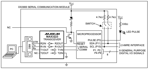
Figure 1. Functional Diagram.
Each 2-wire command consists of two bytes. The first byte in each command determines the type of operation to be performed. The second byte will vary except for the start and stop commands. The second control byte consists of the device identifier, device address, and R/W bit. When the R/W bit is set to 0, data is written to the device. To read from a device, the R/W bit in the first control command should be set to 0 and the R/W bit in the second control command should be set to 1. The second register address byte is the register that is being written or read and the data to send or receive is in the second data byte. After each command is sent to the device, an acknowledge byte or bytes is received.
Table 1. Example of Writing to Register 0x02h in the DS1086
Table 2. Example of Reading From Register 0x02h in the DS1086
The following hardware components were used to communicate to a DS1086 with the LabVIEW VI: PC with a serial port, DS3900, and a DS1086. Figure 2 shows how to connect the DS1086 to the DS3900.
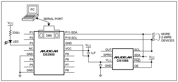
Figure 2. Typical Operating Circuit.
The communicate_2wire.vi performs the following actions (also see Figure 3):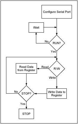
Figure 3. Communicate_2wire.vi Flow Chart.
To use the LabVIEW program: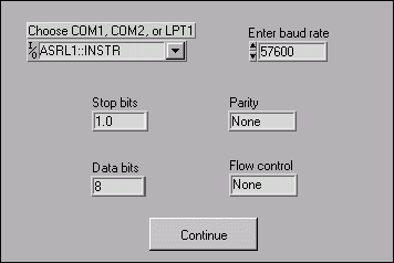
Figure 4. Enter Serial Port Settings Front Panel.
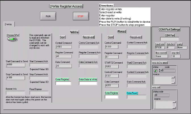
Figure 5. Communicate_2wire.vi Front Panel.
The internal structure of the VI follows the sequence shown below (also shown in more detail in Figure 3). First, the VI reads in the serial port settings provided by the user and displays the chosen settings on the front panel. Figure 6 shows the section of the LabVIEW VI diagram that configures the serial port settings.
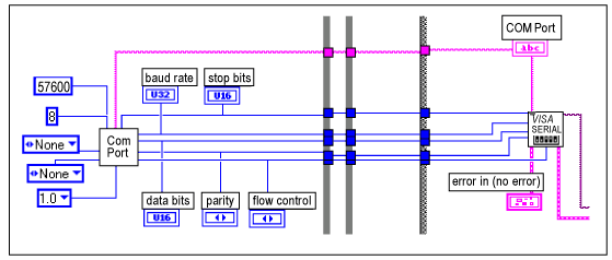
Figure 6. Enter Serial Port Information.
When the RUN button is clicked, the program sends the data entered on the front panel through the serial port to the DS3900 and finally to the 2-wire device. If the user chooses to write data, the write loop completes (see Figure 7).
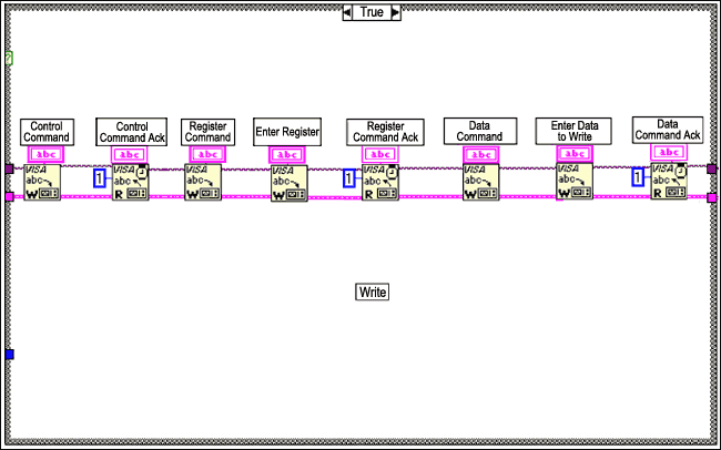
Figure 7. Serial Write.
In Figures 7 and 8 the start command has already been completed. Next, the control command is sent to the DS3900 and the acknowledge byte is returned. An acknowledge byte is always read after a command byte is sent. After the data command is complete the stop command is sent.
If the user chooses to read data, the read loop will complete (see Figure 8).
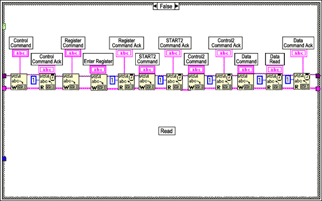
Figure 8. Serial Read. After the write or read is completed, the program waits for the user to write or read another register or stop the program. If the STOP button is clicked, the program will stop even if it is not finished writing to the 2- wire device.
The DS1086 was shown as an example in this application note of how to read and write from one-byte registers, but any 2-wire device can be used with the LabVIEW VI.
The LabVIEW VI can be found in a zip file (2wire.zip). There are two VIs in the zip file: communicate_2wire.vi and Get COM Port Settings2.vi. Get COM Port Settings2.vi is a VI that communicate_2wire.vi references.
For any questions please contact MixedSignal.Apps@dalsemi.com.
NOTE: The software is provided "as is", without warranty of any kind, express or implied, including but not limited to the warranties of merchantability, fitness for a particular purpose and noninfringement. In no event shall Dallas Semiconductor be liable for any claim, damages or other liability, whether in an action of contract, tort, or otherwise, arising from, out of, or in connection with the software or the use or other dealings in the software.
打开APP阅读更多精彩内容
This application brief describes how to use LabVIEW, via a PC serial port to control a 2-wire interface. An interface to a DS1086 is given as an example. The brief also describes how to configure the LabVIEW graphical user interface (GUI) to communicate to the DS3900 serial port adapter. Examples are given on how to manipulate the register settings in a DS1086 low-EMI EconOscillator™. Flow charts showing the details on how to communicate to the DS1086 are provided.
The DS3900 serial port to 2-wire adapter is not a product intended for sale except in development kits offered by Dallas Semiconductor in support of 2-wire devices such as the DS1086. Although, written for the DS1086, this application note can be used to develop a LabVIEW-based interface to any Dallas or Maxim 2-wire devices.
Introduction
LabVIEW is a graphical programming tool that is used in the lab to interface with hardware and lab equipment. The graphical LabVIEW program replaces traditional code, which reduces development time by using the pre-made modules, called Virtual Instruments (VIs). LabVIEW has serial VIs that communicate to the serial port on a PC. These serial VIs can be used to communicate with a 2-wire device using a DS3900 that accepts data and commands from the serial port and converts the information to 2-wire protocol.This application note provides an example showing how LabVIEW can be used to communicate with 2-wire devices. The LabVIEW example VI can be downloaded from the Dallas Semiconductor FTP site. The LabVIEW software package is required in order to run the LabVIEW example VI.
Hardware Requirements
The only hardware that is required to use the LabVIEW example VI is a DS3900. Although, if a customer application board has a means to communicate 2-wire, the DS3900 is not needed but the LabVIEW example VI may need to be modified.The DS3900 provides a way to communicate 2-wire using a PC's serial port. The DS3900 utilizes a MAX3223 RS232 transceiver to translate the serial port signal levels from ±12V to voltage levels for a microprocessor. The microprocessor is then able to communicate to the PC by using its universal asynchronous receiver transmitter (UART). The functional diagram for the DS3900 is shown in Figure 1. For more information, refer to the DS3900 data sheet.

Figure 1. Functional Diagram.
2-Wire Protocol
The LabVIEW example VI (communicate_2wire.vi) communicates over the serial port using DS3900 2-wire commands. When writing to a device, the following commands need to be sent: start, control, register address, data, and stop. When reading from a device, the following commands need to be sent: start, control, register address, start (repeated), control, data, and stop. All commands are in hexadecimal. See the DS1086 2-Wire Example section.DS1086 2-Wire Example
The DS1086 is a programmable frequency synthesizer that has a 2-wire interface. An example of the bytes sent and received during 2-wire communication for the DS1086 is shown in Tables 1 and 2. In this example, the VI will write and read F0h to register 02h in the DS1086. Although the DS1086 is used in this application note, any 2-wire device can be used with the LabVIEW example VI.Each 2-wire command consists of two bytes. The first byte in each command determines the type of operation to be performed. The second byte will vary except for the start and stop commands. The second control byte consists of the device identifier, device address, and R/W bit. When the R/W bit is set to 0, data is written to the device. To read from a device, the R/W bit in the first control command should be set to 0 and the R/W bit in the second control command should be set to 1. The second register address byte is the register that is being written or read and the data to send or receive is in the second data byte. After each command is sent to the device, an acknowledge byte or bytes is received.
Table 1. Example of Writing to Register 0x02h in the DS1086
| Command | 1st Byte Sent | 2nd Byte Sent | 1st Byte Received | Notes |
| Start | 0xA0 | 0x00 | 0xB0 ack |
2-Wire Start |
| Control | 0xA1 | 0xB0 | 0xB1 ack |
Device Identifier = 1011, Device Address = 000, R/W = 0 |
| Register Address |
0xA1 | 0x02 | 0xB1 ack |
Send Register Address (0x02) |
| Data | 0xA1 | 0xF0 | 0xB1 ack |
Send Data to Write (0xF0) |
| Stop | 0xA3 | 0x00 | 0xB3 ack |
2-Wire Stop |
Table 2. Example of Reading From Register 0x02h in the DS1086
| Command | 1st Byte Sent | 2nd Byte Sent | 1st Byte Received | 2nd Byte Received | Notes |
| Start | 0xA0 | 0x00 | 0xB0 ack |
2-Wire Start | |
| Control | 0xA1 | 0xB0 | 0xB1 ack |
Device Identifier = 1011, Device Address = 000, R/W = 0 | |
| Register Address |
0xA1 | 0x02 | 0xB1 ack |
Send Register Address (0x02) | |
| Repeated Start |
0xA0 | 0x00 | 0xB0 ack |
2-Wire Start | |
| Control | 0xA1 | 0xB0 | 0xB1 ack |
Device Identifier = 1011, Device Address = 000, R/W = 1 | |
| Data | 0xA2 | 0x00 | 0xF1 ack |
0xB2 ack |
Send Data to Write (0xF0) |
| Stop | 0xA3 | 0x00 | 0xB3 ack |
2-Wire Stop |
The following hardware components were used to communicate to a DS1086 with the LabVIEW VI: PC with a serial port, DS3900, and a DS1086. Figure 2 shows how to connect the DS1086 to the DS3900.

Figure 2. Typical Operating Circuit.
LabVIEW
The LabVIEW program (communicate_2wire.vi) allows the user to enter serial port settings and either read or write to the 2-wire device.The communicate_2wire.vi performs the following actions (also see Figure 3):
- Prompts user for serial port settings
- Configures serial port
- Determines whether to read or write to a register by user input
- Writes or reads register entered by user
- Returns acknowledge bytes
- Returns value in register during a read

Figure 3. Communicate_2wire.vi Flow Chart.
To use the LabVIEW program:
- Download 2wire.zip from Maxim's FTP site
- Unzip the files and double-click on communicate_2wire.vi
- Enter serial port settings and click Continue (see Figure 4)
- Enter register (see Figure 5)
- Enter data, if writing
- Click on RUN
- Click on STOP when finished running program and close application

Figure 4. Enter Serial Port Settings Front Panel.

Figure 5. Communicate_2wire.vi Front Panel.
The internal structure of the VI follows the sequence shown below (also shown in more detail in Figure 3). First, the VI reads in the serial port settings provided by the user and displays the chosen settings on the front panel. Figure 6 shows the section of the LabVIEW VI diagram that configures the serial port settings.

Figure 6. Enter Serial Port Information.
When the RUN button is clicked, the program sends the data entered on the front panel through the serial port to the DS3900 and finally to the 2-wire device. If the user chooses to write data, the write loop completes (see Figure 7).

Figure 7. Serial Write.
In Figures 7 and 8 the start command has already been completed. Next, the control command is sent to the DS3900 and the acknowledge byte is returned. An acknowledge byte is always read after a command byte is sent. After the data command is complete the stop command is sent.
If the user chooses to read data, the read loop will complete (see Figure 8).

Figure 8. Serial Read. After the write or read is completed, the program waits for the user to write or read another register or stop the program. If the STOP button is clicked, the program will stop even if it is not finished writing to the 2- wire device.
Conclusions
This application note shows how to communicate with a 2-wire device using a LabVIEW VI. There are many advantages to using the LabVIEW 2-wire program. The LabVIEW program helps to reduce development time in two ways: no software needs to be written and no additional hardware except for the DS3900 is needed. LabVIEW can also be used to automate device testing by interfacing LabVIEW with GPIB equipment.The DS1086 was shown as an example in this application note of how to read and write from one-byte registers, but any 2-wire device can be used with the LabVIEW VI.
The LabVIEW VI can be found in a zip file (2wire.zip). There are two VIs in the zip file: communicate_2wire.vi and Get COM Port Settings2.vi. Get COM Port Settings2.vi is a VI that communicate_2wire.vi references.
For any questions please contact MixedSignal.Apps@dalsemi.com.
NOTE: The software is provided "as is", without warranty of any kind, express or implied, including but not limited to the warranties of merchantability, fitness for a particular purpose and noninfringement. In no event shall Dallas Semiconductor be liable for any claim, damages or other liability, whether in an action of contract, tort, or otherwise, arising from, out of, or in connection with the software or the use or other dealings in the software.
声明:本文内容及配图由入驻作者撰写或者入驻合作网站授权转载。文章观点仅代表作者本人,不代表电子发烧友网立场。文章及其配图仅供工程师学习之用,如有内容侵权或者其他违规问题,请联系本站处理。
举报投诉
-
使用ADC3424EVM的2-wire模数转换,ADC3424需要配置吗?2024-11-22 267
-
MAX11208: 20-Bit, Single-Channel, Ultra-Low-Power, Delta-Sigma ADC with 2-Wire Serial Interface Data Sheet MAX11208: 20-Bit, Single-Channel,2023-10-13 53
-
如何使用PC并口与2-Wire设备通信2023-06-09 2136
-
用C语言编写并行端口2-Wire软件2023-02-20 1539
-
用于2-Wire总线应用的上升时间加速器电路2023-01-16 2203
-
AD5306/AD5316/AD5326:2.5V对5.5 V、400 A、2-Wire接口、Quad Voltion输出8/10/12位数据Sheet2021-04-14 574
-
1-Wire总线主机2012-10-19 1167
-
Bluetooth to 1-Wire communicat2010-02-27 1460
-
MAX9621,pdf datasheet (2-wire Hall-effect sensors to low voltage microprocessors)2009-12-17 1329
-
Using Dallas' 1-Wire ICs i2009-04-30 1469
-
Writing Parallel-Port 2-Wire S2009-04-28 1808
-
White Paper 2: Using the 1-Wir2009-04-17 1293
-
DS1629 pdf datasheet (2-Wire D2008-12-08 682
-
2-Wire Intercom circuits-双路对讲机2008-03-15 1340
全部0条评论

快来发表一下你的评论吧 !

