
Logarithmic LED Panel Display
显示光电
描述
Logarithmic LED Panel Display Has 72dB Range
Abstract: This application note presents a simple, stand-alone panel-display circuit that drives a 12-LED logarithmic column. The LED column is a 12-step log indicator with 6dB step height, forming a total column range of 72dB. The circuit's accuracy and stability are defined by the specifications for the design's ADC. The MAX1276 12-bit ADC is featured.
This design idea appeared in the October 31, 2006 issue of EE Times magazine.
Panel-level logarithmic-column displays are usually built in one of two configurations: an analog logarithmic converter and a column-display ADC; or the combination of a high-resolution ADC, a processor-controlled logarithmic algorithm, and an LED or LCD column driver.
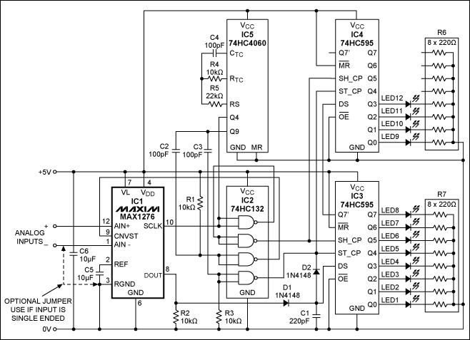
There is a simpler, all-digital alternative consisting of a serial-output ADC and some timing and display electronics (Figure 1). A stand-alone circuit, it requires no trimming (as analog versions do), no microcontroller, and no software. The signal to be displayed is applied to a 12-bit ADC (IC1, the MAX1276). For the circuit shown, that signal can range from zero (no LED on) to +2.048V (all LEDs on), with the first LED coming on at +1mV.
When triggered by a short positive pulse at CNVST, the MAX1276 begins a conversion, clocked by the signal at SCLK. Its output (DOUT) is clocked by the rising edge of SCLK and starts with four leading zeros, followed by the 12-bit conversion result, MSB first. Thus, one conversion result requires 16 clock pulses at SCLK.
The display is a vertical stack of 12 LEDs in which the top LED represents the MSB. During operation, the circuit scans each conversion result as it is generated (MSB first, as described above). It notes the first bit with a value of "1," and then proceeds to illuminate that LED and all those below it. The result is a logarithmic column in which the input-voltage change necessary to move the column one step up or down is double or half the current input value (a 6.02dB step). The number of steps available equals the ADC's resolution (12 bits in this case).
Figure 1. This stand-alone panel-display circuit drives a 12-LED logarithmic column, whose height changes by one LED for each 6.02dB change in the input voltage.
At DOUT, the first output bit with a value of "1" charges C1 (with diode D1) to the logic-one level. The voltage on C1 connects to the data input (DS) of the first of two cascaded 74HC595 ICs, which together form a 16-bit shift register. The signal that clocks the ADC, slightly delayed, also clocks the shift register, thereby inserting into the shift register the value presented at its input. At the end of the conversion, all bits following the first one to exhibit a "1" value are also forced to "1" by the voltage stored on C1.
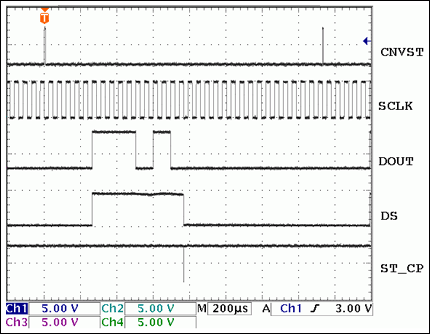
After each conversion is finished, a negative pulse is applied to the SC_TP inputs of both 74HC595 ICs (Figure 2). This action transfers the internal shift-register contents to an internal parallel-output register. The same pulse discharges the storage capacitor through diode D2, leaving the circuit ready for the next conversion scan. The parallel-register outputs then serve as the column LED drivers. A 74HC4060 IC serves as clock and timing sequence generator, and a 74HC132 provides some necessary glue logic.
Figure 2. Timing for the Figure 1 circuit. CNVST: MAX1276 conversion trigger signal; SCLK: MAX1276 conversion clock, and 74HC595 shift clock; DOUT: MAX1276 conversion data out; DS: 74HC595 shift data input; ST_CP: 74HC595 shift-register to parallel-register transfer clock pulse.
Thus, the LED column is a 12-step log indicator with 6dB step height, forming a total column range of 72dB. Its accuracy and stability are those defined by the specifications for the MAX1276. The sampling rate for the display is about 2.5kHz with the component values shown.
- 相关推荐
- 热点推荐
- Display
-
Nextion Display:使用双态按钮控制LED开关2023-02-07 870
-
Arduino Nextion Display使用滑块控制LED亮度2022-10-28 826
-
【平头哥Sipeed LicheeRV 86 Panel测评】闪烁LED2022-03-08 1219
-
Flat Panel Display Controller2017-10-17 1370
-
Proteus在MCS&ARM中的应用之LED_Display2016-01-20 488
-
苹果Thunderbolt LED Cinema Display新品曝光2011-07-16 1102
-
TL441,pdf(Logarithmic Amplifie2010-09-26 754
-
LED显示数字电压表电路,Led display digit2010-04-11 5102
-
FLAT-PANEL DISPLAY(平板显示器)2009-11-20 949
-
AD8307,pdf datasheet (Logarithmic Amplifier)2009-08-27 1141
-
驾驶4-1/2数字仪表显示与MAX6958/59LED驱动器2009-04-27 1179
-
Display Different LED Sequence2009-03-31 1344
-
Display Backlighting Using Hig2009-02-06 1233
-
Common Panel Meter Setup Probl2009-01-13 891
全部0条评论

快来发表一下你的评论吧 !

