

Rail-to-Rail: Railroading and
接口/总线/驱动
1159人已加入
描述
Rail-to-Rail: Railroading and the Electronics of Op Amps
Abstract: Railroads have had rail-to-rail components for years that were, in fact, nearly rail to rail. Op amps employ the same nearly rail-to-rail tradition. This application note discusses rail-to-rail op amps, and explains why some inputs and outputs can be less than, nearly, or slightly more than the power rails.
Introduction
For some, rail travel conjures up nostalgic images. They look at an old train engine and it represents a time and lifestyle from a bygone era. It suggests a simpler, slower time. That image is nothing like today's commute or even air travel. Most business trips today are done on the run. Sadly, waiting in airport security lines is about the only time that we are not racing around.Figure 1. Railroad use of "rail-to-rail" flanged wheels.
The flanged wheels on rail equipment (Figure 1) guide the wheels on the rails. Steam, diesel, electric, even bullet trains run on rail-to-rail, flanged wheels every day. Around corners and through switches the flanges steer the heavy loads. Do the wheel flanges span rail to rail? Yes, but not quite. In order to turn, the wheels need a little clearance. The manufacturing tolerances of wheels, axles, tracks, and thermal expansion need to be understood to make a safe operating railroad.
Maxim's operational amplifiers' (op amps) use of rail to rail has nothing to do with railroads. Nonetheless, railroads make an excellent mental image to describe the phenomenon. Just as a train's rails place limits on the lateral movement of a train, op-amp power rails place limits on the voltage swing at the input and output. As in a railroad, for op amps "rail to rail" can mean "almost rail to rail." As we will see, the term can mean different things for inputs and outputs. It could also mean more than just rail to rail.
Rail-to-Rail and Modern Op Amps
Early op amps had output drives that ran out of current as the signal approached the power-supply rails. When the signal was a few volts peak to peak and the power supplies were plus and minus 12V or 15V, there was no problem. However, as the power supplies reduce, rail-to-rail signal swings become very desirable. Circuit configurations have thus changed with the time. Both rail-to-rail and Beyond the Rails™ inputs and rail-to-rail outputs are common on modern op amps.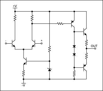
Figure 2. An early op amp with six transistors.
The first op amps used vacuum tubes (hollow state devices) then discreet transistors, as in Figure 2. Those circuits led to integrated op amps. Today's integrated circuits are very sophisticated with complicated circuits utilizing hundreds of transistors.
Rail-to-Rail Inputs
Op-amp input stages for rail-to-rail inputs use two pairs of transistors. The active devices can be MOS (Figure 3), bipolar (Figure 4), or CMOS.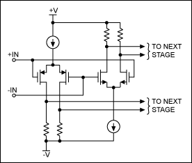
Figure 3. A MOS rail-to-rail input stage.
As with most engineering there are trade-offs in performance among devices. Temperature stability, input impedance, frequency response, and offset currents vary across the different transistor families. This means that the choice of transistor is application dependent.¹
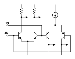
Figure 4. Bipolar op amp input stage.
In Figures 3 and 4 the "P" input pair will be active near the most negative power-supply limit. The "N" input pair will be active near the most positive power-supply limit. Somewhere in the center of the operating range, the signal must transition from one pair to the other. At the transition, distortion will rise and the input currents will change between the pairs (Figure 5). This is illustrated in the case of the MAX4122. As the common-mode input voltage of the rail-to-rail input amplifier sweeps from one supply rail to the other, the input bias current changes both in sign and in magnitude. Much of the modern IC technology is centered on reducing the distortion and balancing the currents.
Unlike other rail-to-rail op amps, in the MAX4091 family of op amps the transition region has been widened to approximately 600mV to minimize the slight degradation in CMRR caused by this mismatch. A careful study of the data sheet is important to understand these issues. In low-voltage, low-current op amps it is not uncommon to see both a warning about the crossover distortion, and a recommendation to bias a sensitive signal to avoid the crossover point.
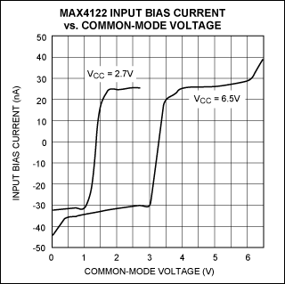
Figure 5. Bias change in a rail-to-rail input stage for the MAX4122 op amp.
Even though the MAX4091 op-amp family is made with a bipolar process, the input bias currents are typically less than 20nA. Since the bias current flows into the device when the NPN input stage is active and flows out when the PNP input stage is active, it is necessary to consider the effects of that current. To reduce the offset error caused by input bias current flowing through external source resistances, those impedances should be well matched. The data sheet discusses this in detail.
There is another important feature to look for in an op-amp data sheet, a statement similar to the following: there is no phase reversal or latchup for overdriven inputs. Both were a common problem in early op amps and they raise havoc in most circuits. Some latchup conditions even resulted in destroying the devices.
With typical rail-to-rail op amps like the MAX4091 family, the input common-mode range extends 50mV beyond the positive and negative supply rails. This range has evolved to 100mV beyond the positive and negative supply rails for the MAX9910 family. Further improvement resulted in the development of the proprietary Beyond-the-Rails technology in the MAX4220 and MAX4091 families. These latter devices can extend 200mV beyond the positive and negative supply rails.
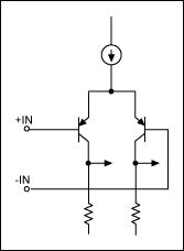
Figure 6. Input circuit which includes a ground in the input range.
Figure 6 shows the typical bipolar configuration of an op amp that includes the ground rail in the common-mode range. Bipolar parts which exhibit this negative-rail capability are the MAX4493 and LMX321 families. CMOS-equivalent parts are the MAX4475 and MAX4036 families.
Rail-to-Rail Outputs
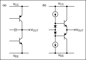
Figure 7. A rail-to-rail output stage (a) and the standard output stage (b).
Like the railroad wheel flanges that go almost rail to rail, the output circuits of op amps go almost rail to rail. The crucial data-sheet information about this is a statement that says the output voltage swings to within "n" mV of the supplies with an "n" Ω load.
A rail-to-rail output stage (Figure 7a) has a common-emitter configuration, while a standard output stage (Figure 7b) has an emitter-follower configuration. Watch the data sheet load condition. One might expect the load to be connected to ground, but often the load is connected to one-half of the power-supply values. The rail-to-rail output specifications are always with light loading. As the load (current) increases, the amplifier is less able to swing near the rails. Therefore, if a low-distortion large current is required at a voltage near the power-supply amplitude (rail), one must consider increasing the power-supply voltage and use a conventional op amp. An alternative is to use the MAX4162 op-amp family, which takes a novel approach to the problems of the standard rail-to-rail output stage. These op amps have a classic emitter-follower output stage, but achieve rail-to-rail outputs with an internal charge-pump converter that provides internal supply voltages to bias several amplifier stages, including the output stage. Thus, the input stage has a standard ground-sensing configuration, but allows inputs to swing from ground to VCC2. As is always true, the application dictates the best circuit configuration.
Summary
Rail-to-rail op amps have a range of typical output swings for various devices. A typical output swing for the MAX4091 family is to within 15mV of the supplies with a 100kΩ load. When connected as a voltage-follower, the MAX4321's output swings from 0.02V to 2.97V with a +3V supply and with a 100kΩ load to ground. For the MAX4321 the maximum output-voltage swing depends on the load, but will be within 300mV of a +5V supply, even with the maximum load of 250Ω to ground. When connected as a voltage-follower, the MAX4230 is guaranteed to be within 500mV of the positive rail (VDD = 2.7V) even with maximum load of 32Ω to ground. The output stage for the MAX4240–MAX4244 can drive up to a 10kΩ load and still swing to within 40mV of the rails. Thus the application helps define the proper part.Traveling by rail is nostalgic and the rail-to-rail flanged wheels are still guiding trains. With op amps, we have seen that "rail to rail" for inputs can even mean Beyond the Rails. For outputs, just like the railroad, it can mean almost rail to rail. Likely op amps will continue to improve as technology advances, and because of their benefits they will be used for many years.
声明:本文内容及配图由入驻作者撰写或者入驻合作网站授权转载。文章观点仅代表作者本人,不代表电子发烧友网立场。文章及其配图仅供工程师学习之用,如有内容侵权或者其他违规问题,请联系本站处理。
举报投诉
- 相关推荐
- 热点推荐
- a
-
ADA4511-2: Precision, 40 V, Rail-to-Rail Input and Output Op Amp with DigiTrim Data Sheet adi2025-01-15 60
-
轨到轨(rail-to-rail)运算放大器讲解2023-02-14 18803
-
请教RAIL-TO-RAIL运放和普通运放有什么区别2021-11-12 2007
-
LTC1458:四路12位Rail-to-Rail Micropower DAC产品手册2021-05-26 699
-
AD627:微功耗、单电源和双电源Rail-to-Rail仪表放大器数据表2021-05-12 921
-
LTC1454:双12位Rail-to-Rail Micropower DAC产品手册2021-05-08 741
-
LTC1663:带2线接口的10位Rail-to-Rail微功率DAC产品手册2021-04-26 670
-
LTC1658:14位Rail-to-Rail Micropower DAC数据表2021-04-22 753
-
UG-1736: Evaluating the LTC6227 and LTC6229 Low Distortion, Rail-to-Rail Output Op Amps2021-01-30 672
-
详解轨到轨rail-to-rail输出运算放大器2019-05-07 3463
-
A Low Voltage,Rail-to-Rail,Class AB CMOS Amplifie2017-10-17 918
-
rail-to-rail放大器资料2012-12-25 1778
-
什么是rail-to-rail operational am2007-09-20 5128
全部0条评论

快来发表一下你的评论吧 !

