
Logic-Level Signals Dim -48V L
显示光电
描述
Logic-Level Signals Dim -48V LED Driver
Abstract: A 65V hysteretically controlled LED driver (MAX16822A) has its ground pin connected to -48V and its power input connected to the system ground. For dimming, the circuit's logic-level control signal (control) is level-shifted down to -48V and applied to the DIM input, using an 80V/500mA high-voltage PNP transistor (CMPT5551).
This design idea appeared in the June 23, 2009 issue of ED magazine.
The main source of power in a telecommunication system is -48V. Not only the negative polarity of this source, but also its large magnitude with respect to ground pose a challenge when including low-power ICs in the application circuits of a telecom system. The emergence of high-voltage ICs with operating voltages of 75V and higher, however, has enabled the use of simple biasing techniques in designing circuits for -48V systems.
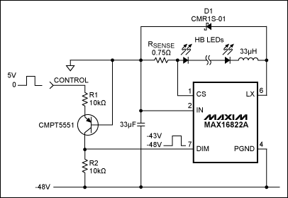
In Figure 1, a 65V hysteretically controlled LED driver (MAX16822A) has its ground pin connected to -48V and its power input connected to the system ground. For proper dimming, therefore, the circuit's logic-level control signal (at Control) must be level-shifted down to -48V and applied to the DIM input. The high-voltage PNP transistor CMPT5551 (80V/500mA) enables a simple solution to that problem.
Figure 1. This LED driver applies -48V to the LEDs, but accepts a 0-to-5V dimming signal.
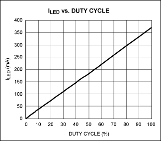
The transistor circuit is made to operate at approximate unity gain by setting R1 equal to R2. With the control input at 0V the transistor is biased at cut-off, pulling the collector (connected to DIM) down to -48V. With the control input at 5V, the collector pulls up to -43V. Thus, the ground-referenced 0-to-5V dimming signal at the control input is replicated at DIM, but referenced to the -48V rail. Average LED current vs. PWM duty cycle is shown in Figure 2. A data sheet and other information on the MAX16822 is available at www.maxim-ic.com.
Figure 2. In Figure 1, the LED current vs. the duty cycle at DIM is quite linear.
-
特斯拉Cybertruck的48V电池系统技术2024-03-29 3134
-
基站48V接口EMC设计标准电路2022-10-21 702
-
48V无光隔离应用2021-05-22 901
-
LT8331 Demo Circuit - 48V SEPIC Converter (36-72V to 48V @ 165mA)2021-03-11 1020
-
LT8362 Demo Circuit - 48V Boost Converter (12-36V to 48V @ 300mA)2021-02-05 993
-
LT8365 Demo Circuit - 48V SEPIC Converter (12-60V to 48V @ 200mA)2021-01-28 1021
-
如何理解-48V供电?2020-05-06 2626
-
汽车48V系统的发展和应用_48V系统现状和未来趋势2018-04-26 5414
-
浅析48V汽车系统2017-11-20 1439
-
-48V供电怎么理解?2016-04-25 19741
-
MAX14595 High-Speed, Open-Drain Capable Logic-Level Translator2012-01-23 2644
-
TPS65190,pdf(10-Channel Level2010-11-03 664
-
Level Shifting Digital Signals2009-08-21 1253
全部0条评论

快来发表一下你的评论吧 !

