
Integrated Solutions Make Anal
模拟技术
描述
Integrated Solutions Make Analog Filter Design Easy
Abstract: This application note explains advances of switched-capacitor analog filters for anti-aliasing and noise filtering for ADCs (analog-to-digital converters), as well as "reconstruction" post-filtering for DACs (digital-to-analog converters). The article summarizes the unique benefits of the MAX74xx series filter vs. continuous-time active filters and provides application examples.
Analog filters play an important part in electronic signal-synthesis subsystems, providing functions such as anti-aliasing and noise filtering for ADCs, and reconstruction post-filtering for DACs.¹ Different design specifications and requirements dictate the use of the particular filter configurations. The most popular filters include Bessel, Butterworth, and elliptic.
Bessel lowpass filters provide a linear phase response with a ripple-free passband and monotonic rolloff. These characteristics make Bessel filters ideal for time domain applications. Butterworth lowpass filters have a maximally flat frequency response in the passband with a monotonic rolloff that is much sharper than the Bessel filter. Their phase response varies nonlinearly with frequency. These characteristics present no problems for amplitude-based applications. Finally, elliptic lowpass filters have a nearly flat passband response with an extremely sharp rolloff characteristic. Elliptic filters are ideally suited to amplitude-based anti-aliasing applications.
Design and construction of continuous-time active filters pose substantial design challenges and require the use of multiple high-performance op amps surrounded by many matched tight-tolerance passive components. Design challenges include selection of the optimal filter configuration, as well as the use of specialized software for filter synthesis.² A simpler approach might include the use of highly integrated SCFs (switched-capacitor filters)—such circuits can reduce the number of components, make it easier to tune the filter, and trim system power. This article will examine a filter implementation, first using a continuous-time filter and then with an SCF approach to show the differences in performance and complexity.
As mentioned previously, due to their characteristics, Bessel filters are ideal for time domain applications, as they have no distortion in the oscilloscope/analyzer type measurements. However, the cost for the perfect characteristic filter is that the designer must construct a higher order Bessel filter (having more poles than a Butterworth or elliptic filter) to achieve a suitable level of stopband attenuation.
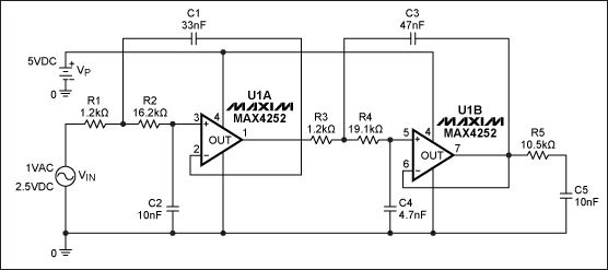
Figure 1 shows a schematic for a 5th-order, 1.0kHz, lowpass Bessel filter. This design is based on Sallen-Key architecture, is optimized for minimum component count, and uses standard-value 1%-tolerance resistors and 5%-tolerance ceramic capacitors. To determine the component values, the design was created using FilterPro™ software and "tested" using PSPICE simulation tools.
Figure 1. Two op amps and a handful of passive parts comprise this 5th-order, 1.0kHz, lowpass Bessel filter.
In many cases, input and output RC filters also require additional op amp buffers, particularly if the signal source impedance is relatively high (above a few hundred ohms) and the output of the filter is connected to the relatively low impedance circuit (below several hundred kilohms).
SPICE simulations run on the Bessel filter circuit are shown in Figure 2. These frequency response plots are the result of a Monte Carlo run of 100 different virtual manufacturing builds for the same filter. The SPICE simulator randomly varies the component values within their specified tolerances to account for manufacturing variances. The results of the simulation demonstrate a passband variation around fC = fIN -3dB ± 0.6dB due to capacitor and resistor values spread in their tolerance ranges.
Figure 2. These frequency response plots show the results of SPICE simulations of the five-pole Bessel filter.
To achieve acceptable filter characteristics at 1kHz to 15kHz cutoff frequencies (for 80dB dynamic range or better), designers must use components with even tighter tolerances and better temperature stability. For example:
- Amplifiers must exhibit a required unity gain of 0.5MHz to 6.5MHz for 1kHz to 15kHz cutoff frequencies and a THD+N (total harmonic distortion plus noise) factor of better than 0.005%.
- Capacitors should be precision ceramic or film capacitors. These capacitors should hold their nominal value over wide temperature and voltage ranges.
- Resistors should be the metal film type with ±1% or better tolerances and a low temperature coefficient.
- To ensure that the components deliver the desired characteristics, they should be acquired from reputable sources such as Panasonic, Rohm, Vishay, Kemet, and AVX.
Preliminary estimates show that component cost of the 5th-order, 1kHz to 15kHz cutoff frequency, lowpass Bessel filter could be in the range $1.50 to $2.00 (1000-up pricing). This does not include incremental time expenses for design, test, PCB layout, assembly, components procurement, and so on; these expenses are difficult to quantify and will vary from company to company. For more detailed information regarding component-variation sensitivity for high-order, continuous-time filters, see application note 738, "Minimizing Component-Variation Sensitivity in Single Op Amp Filters."
Maxim offers a much more efficient, less complex approach by providing an integrated solution based on switched-capacitor technology, which allows most of the filter function to be integrated on a single silicon IC. (Application note 733, "A Filter Primer," provides additional information regarding SCF operations.) All that the designer must do to set up a particular filter characteristic is to use a single, inexpensive external capacitor or external clock. The result is a compact, reliable, predictable, cost-effective filter design that is less susceptible to temperature and other variations.
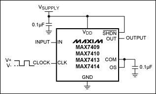
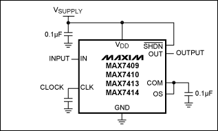
Figures 3 and 4 show the simple circuit implementations for 5th-order, low-pass Bessel filter based on SCF chips (the MAX7409/MAX7413). The decoupling, 0.1µF capacitors could be the generic, low-cost ceramic type (dielectric type X7R or Z5U). However, for CCLK in Figure 4, a COG (NPO) dielectric type is recommended.
Figure 3. Setting fC (cutoff frequency) for a switched-capacitor filter circuit can be done by using an external clock with a 50% ± 10% duty cycle.
Figure 4. Setting fC by using the switched-capacitor filter's internal oscillator requires connecting the CCLK capacitor between CLK and ground. At CCLK = 300pF, fC = 1kHz.
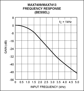
Simulations and test results (shown in Figure 5) indicate an improvement in passband variation for a MAX7409/MAX7413-based design vs. a continuous-time, op-amp-based design. Another advantage of these two integrated solutions is easy tunability. The cutoff frequencies are clock tunable with two clocking options available: self-clocking or external clocking. In comparison, changing the cutoff frequency in the op-amp-based design often requires fundamental redesign.
Figure 5. Passband variation at fC = fIN is only -3dB ± 0.4dB over temperature and voltage.
Tables 1 and 2 illustrate a few of the many integrated filter solutions from Maxim that consume little power, yet deliver high-order-filter characteristics.
Table 1. Maxim's Family of Low-Power, 5th-Order Filters
| Part | Supply Voltage (V) | Filter Type | Filter Characteristics |
| MAX7411 | +5 | Elliptic | Steepest rolloff, 37dB of stopband rejection |
| MAX7415 | +3 | Elliptic | Steepest rolloff, 37dB of stopband rejection |
| MAX7408 | +5 | Elliptic | Steep rolloff, 53dB of stopband rejection |
| MAX7412 | +3 | Elliptic | Steep rolloff, 53dB of stopband rejection |
| MAX7409 | +5 | Bessel | Linear phase response |
| MAX7413 | +3 | Bessel | Linear phase response |
| MAX7410 | +5 | Butterworth | Maximally flat passband and stopband response |
| MAX7414 | +3 | Butterworth | Maximally flat passband and stopband response |
Table 2. Maxim's Family of Low-Power, 8th-Order Filters
| Part | Supply Voltage (V) | Filter Type | Filter Characteristics |
| MAX7400 | +5 | Elliptic | Steepest rolloff and 83dB of stopband rejection |
| MAX7401 | +5 | Bessel | Linear phase response |
| MAX7403 | +5 | Elliptic | Steep rolloff and 60dB of stopband rejection |
| MAX7404 | +3 | Elliptic | Steepest rolloff and 83dB of stopband rejection |
| MAX7405 | +3 | Bessel | Linear phase response |
| MAX7407 | +3 | Elliptic | Steep rolloff and 60dB of stopband rejection |
- 相关推荐
- 热点推荐
- I
-
GNU make中文手册2024-06-05 438
-
make、make all和make clean的使用方法2024-01-05 3130
-
请教Filter Solutions2022-07-15 24455
-
GNU_Make_中文手册下载2017-10-30 745
-
GNU_make中文手册2016-08-23 482
-
could not creat integrated library2016-07-11 15042
-
gnu make 中文手册2015-11-10 575
-
Lattice_Wireless_Solutions2012-08-14 1432
-
gun make教程2010-03-10 1413
-
Agilent Technologies Solutions2010-03-03 447
-
GNU make中文手册 (pdf版下载)2009-10-09 2905
-
Smart Sensor solutions for the automotive industry2009-10-06 2935
-
Make Precise Base-Station Powe2009-09-23 849
-
Solutions For Adaptor and ATX2009-07-03 634
全部0条评论

快来发表一下你的评论吧 !

