


Connecting dual-digit LED modu
显示光电
描述
Connecting dual-digit LED modules
Abstract: The MAX6954/MAX6955 LED display drivers allow users to drive both individual LED digits and shared segment pins. This application note details what steps must be taken to map the digits properly.
Maxim's MAX6954 and MAX6955 LED display drivers can be used to drive LED digits whose segment pins are individually available. The MAX6954/MAX6955 can also be used to drive dual-digit 7-segment LED modules which feature shared segment pins. Figure 1 shows the internal example configuration of such a device.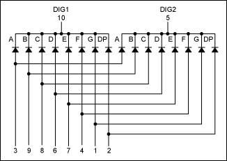
Figure 1. Internal configuration of a dual-digit LED module.
Up to eight dual-digit modules or 16 digits can be driven by just one MAX6954 or MAX6955. The following module digit-to-digit mapping is recommended to connect these modules to the MAX6954/MAX6955.
Module1-Digit1 -> Digit 0               DIG1 -> CC00
Module1-Digit2 -> Digit 1               DIG2 -> CC01

Module2-Digit1 -> Digit 2               DIG1 -> CC02
Module2-Digit2 -> Digit 3               DIG2 -> CC03

Module3-Digit1 -> Digit 4               DIG1 -> CC04
Module3-Digit2 -> Digit 5               DIG2 -> CC05

Module4-Digit1 -> Digit 6               DIG1 -> CC06
Module4-Digit2 -> Digit 7               DIG2 -> CC07

Module5-Digit1 -> Digit 0a       	DIG1 -> CC00
Module5-Digit2 -> Digit 1a              DIG2 -> CC01

Module6-Digit1 -> Digit 2a       	DIG1 -> CC02
Module6-Digit2 -> Digit 3a     	 	DIG2 -> CC03

Module3-Digit1 -> Digit 4a              DIG1 -> CC04
Module3-Digit2 -> Digit 5a              DIG2 -> CC05

Module4-Digit1 -> Digit 6a              DIG1 -> CC06
Module4-Digit2 -> Digit 7a              DIG2 -> CC07
Table 4, Connection Scheme for Sixteen 7-Segment Digits, in the MAX6954/MAX6955 data sheet explains that digit 0, 1, 2, 3, 4, 5, 6, and 7's segment pins are identified by 1a, 1b, 1c, 1d, 1e, 1f, 1g, and 1dp; digit 0a, 1a, 2a, 3a, 4a, 5a, 6a,and 7a's segment pins are identified by 2a, 2b, 2c, 2d, 2e, 2f, 2g, and 2dp.
The scan limit should be set accordingly by writing the proper number to register 0x03. For this example with all eight modules or 16 digits, the scan-limit register should have a content of 0x07. The scan-limit register content can be changed to 0x03 if only four modules or eight digits are driven. When only half of the modules or digits are used, the module digit-to-digit mapping can be changed to the following.
Module1-Digit1 -> Digit 0               DIG1 -> CC00
Module1-Digit2 -> Digit 1               DIG2 -> CC01

Module2-Digit1 -> Digit 2               DIG1 -> CC02
Module2-Digit2 -> Digit 3               DIG2 -> CC03

Module5-Digit1 -> Digit 0a       	DIG1 -> CC00
Module5-Digit2 -> Digit 1a              DIG2 -> CC01

Module6-Digit1 -> Digit 2a       	DIG1 -> CC02
Module6-Digit2 -> Digit 3a       	DIG2 -> CC03
- 相关推荐
- 热点推荐
- led
-
single ram和dual ram的问题2014-02-19 4773
-
在Debug时,出现 Error connecting to the target:2018-11-13 19426
-
怎么将5digit BCD转换为BIN2019-03-26 1071
-
AD9627-11,pdf datasheet (Digit2009-09-08 529
-
ADP1655,datasheet,pdf(Dual LED2009-10-22 621
-
ICL7129,pdf,datasheet,Digit LC2010-03-24 837
-
CAT4134-500 mA Dual Channel Mo2010-04-12 1315
-
TLC7135,pdf (4 1/2-Digit Preci2010-06-03 2085
-
使用MAX6950和MAX6951LED显示驱动器的多重双数2009-04-27 1280
-
Driving 4-1/2 Digit Counter Di2009-05-04 1112
-
dual link/Xvid,dual link/Xvid是2010-04-10 2156
-
LED显示数字电压表电路,Led display digit2010-04-11 5228
-
Connecting_Real_People_with_Real_Solutions2016-01-19 585
-
三星申请Dual LED商标,电视新品或将于CES 2020上正式亮相2019-10-22 5550
-
MAX133-MAX134: 3¾ Digit DMM Circuit Data Sheet MAX133-MAX134: 3¾ Digit DMM Circuit Data Sheet2023-10-13 82
全部0条评论

快来发表一下你的评论吧 !
