
Determining LCM and OVD thresh
模拟技术
描述
Determining LCM and OVD thresholds for the DS3xxx CCFL controllers
Abstract: The DS3881, DS3882, DS3984, DS3988, DS3991, DS3992, and DS3994 are CCFL (cold-cathode fluorescent lamp)controllers that backlight LCDs (liquid crystal displays). Each controller channel has two input pins for lamp monitoring and current regulation, LCM and OVD. There are four thresholds associated with these two inputs. This application note describes how the thresholds are specified and how to determine correct threshold values based on the application.
LCM and OVD thresholds and the corresponding references
Each channel of the DS3881, DS3882, DS3984, DS3988, DS3991, DS3992, and DS3994 CCFL (cold-cathode fluorescent lamp) controllers has two inputs, LCM for lamp current monitoring and OVD for overvoltage detection. There are four thresholds associated with LCM and OVD. Table 1 summarizes the description and symbol for each threshold.
Table 1. Threshold Description and Symbols
| Associated Pin | Symbol | Description |
| LCM | VLOT | Lamp off threshold |
| VLOC | Lamp overcurrent threshold | |
| VLRT | Lamp regulation threshold | |
| OVD | VOVDT | Lamp overvoltage threshold |
Both the LCM and OVD pins have an internal DC bias voltage, VDCB, which is 1.1V for the DS3881 and DS3882, and 1.35V for the DS3984, DS3988, DS3991, DS3992 and DS3994. The thresholds can be referenced to either VDCB or signal ground (GND).
Depending on the voltage reference used, the thresholds specified in the various data sheets may appear to have different values although they are virtually the same. In the DS3881, DS3882, DS3984, and DS3988 data sheets, the four thresholds are referenced to VDCB. In the DS3991, DS3992, and DS3994 data sheets, the four thresholds are referenced to ground and thus include VDCB. For example, the lamp regulation threshold (typical value) for the DS3984 is specified in the data sheet as 1.0V with respect to VDCB, and the VDCB is 1.35V. In the DS3994 data sheet the same parameter is specified as 2.35V and this value is with respect to signal ground. So the lamp regulation threshold of both the DS3984 and the DS3994 is virtually same. In fact, Note 3 in both data sheets explains this.
Determine correct thresholds based on the application
Since the threshold values can differ depending on the reference used, the user needs to correctly determine the reference (either VDCB or ground) and thus select the correct external component values. The general rule is to use VDCB as the reference if the LCM and OVD signals are AC coupled. This is typically the case for a single-lamp-per-channel application. However, the thresholds should be referenced to ground if no AC coupling is used. This guideline typically applies to applications using multiple lamps per channel applications. Two examples explain this principle.
Application with a single lamp per channel
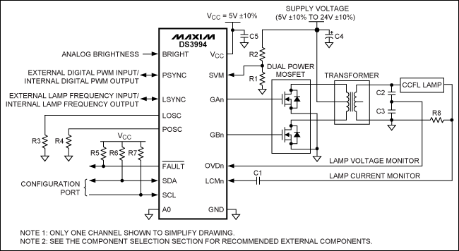
In this application the internal DC bias voltage at the LCM and OVD pins allows for an AC-coupled input. This design can make the external circuitry very simple. A typical operating circuit for this application is shown in Figure 1.
Figure 1. Typical operating circuit with a single lamp per channel.
In this application, the thresholds are referenced to VDCB. The values are listed in Table 2 and may be different for other parts.
Table 2. DS3994 LCM and OVD Thresholds (for Figure 1)
| Parameter | Symbol | Min | Typ | Max | Units |
| Lamp off threshold | VLOT | 0.30 | 0.40 | 0.50 | V |
| Lamp overcurrent threshold | VLOC | 1.80 | 2.00 | 2.20 | V |
| Lamp regulation threshold | VLRT | 0.94 | 1.00 | 1.06 | V |
| OVD threshold | VOVDT | 0.90 | 1.00 | 1.10 | V |
Application with multiple lamps per channel
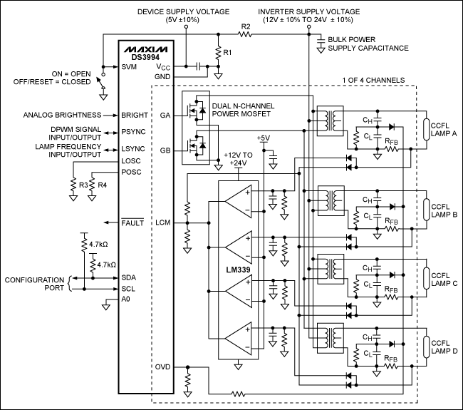
Figure 2 shows a typical operating circuit with multiple lamps per channel using the DS3994. In this application, the lamp currents and voltages must be wire-ORed and fed to the LCM and OVD inputs on the DS3994. Some external circuitry, including voltage-dividers and peak detectors, is used. Unlike the application with a single lamp per channel, the application with multiple lamps per channel does not use an AC-coupling capacitor at the LCM input. The DS3994 controls the lamp current based on the peak signal measured at the LCM input. With no AC-coupling capacitor, the peak control level will be the DC-bias voltage (1.35V) plus the lamp-regulation threshold (1.0V) or 2.35V nominal. Hence, the peak voltage level created by the lamp's current-feedback resistor must be attenuated to a target value of 2.35Vpeak at the LCM input so the device can control the lamp current to the proper level. Similarly, the OVD threshold in this application is 2.35Vpeak with respect to ground. More detail can be found in Maxim's application note 3615, "DS3984/DS3988 Multiple Lamp Drive Scheme."
Figure 2. Typical operating circuit with multiple lamps per channel.
The thresholds used in Figure 2 are summarized in Table 3, voltages with respect to ground. These values may differ for other parts.
Table 3. DS3994 LCM and OVD Thresholds (for Figure 2)
| Parameter | Symbol | Min | Typ | Max | Units |
| Lamp off threshold | VLOT | 1.65 | 1.75 | 1.85 | V |
| Lamp overcurrent threshold | VLOC | 3.15 | 3.35 | 3.55 | V |
| Lamp regulation threshold | VLRT | 2.29 | 2.35 | 2.41 | V |
| OVD threshold | VOVDT | 2.25 | 2.35 | 2.45 | V |
Summary
- Each channel of the DS3xxx CCFL controller has four thresholds for lamp monitoring and regulation.
- The thresholds may appear with different values in the respective data sheets depending on the reference used.
- The thresholds are typically referenced to the DC bias voltage (VDCB) when the LCM and OVD signals are AC coupled. This approach typically applies to the single-lamp-per-channel applications.
- The thresholds are referenced to ground when the LCM and OVD signals are connected to the corresponding pins without AC-coupling capacitors. This design typically applies to applications with multiple lamps per channel.
- 相关推荐
- 热点推荐
- C
-
Arm Lifecycle Manager(LCM)规范2023-08-09 722
-
LCM液晶显示模组选胶指南——包含ITO保护、COG保护等用胶点2023-03-27 4833
-
SMC1602A LCM液晶屏中文手册2021-11-21 1351
-
LCM调试SOP2021-07-27 941
-
lcm模组需要做哪些测试2018-02-03 14099
-
MTK Android Driver LCM2016-09-19 6380
-
SMC1602A LCM说明书2012-02-20 1827
-
LCM显示类型2010-12-15 759
-
LCM液晶流动显示.wps2010-12-01 2540
-
确定DS3xxx CCFL控制器的LCM和OVD门限2010-08-21 1405
-
Determining Clock Accuracy Req2009-03-31 1199
-
LCM是什么意思?什么叫LCM?2008-10-30 27732
-
LCM使用注意事项2006-04-16 1604
全部0条评论

快来发表一下你的评论吧 !

