
手工打造能分析CMOS和TTL电路的分析仪
描述
这是发布在Hackster.io上的一个项目,作者为John Bradnam,一个很小的分析仪能分析CMOS和TTL电路,能够测量5种状态,检测脉冲并针对不同的状态播放不同的声音。
国外的玩家没有我们方便,做个PCB是件很折腾的事情,因此简单的电路都要想办法手工打造。
下面就是这个项目的简单介绍:
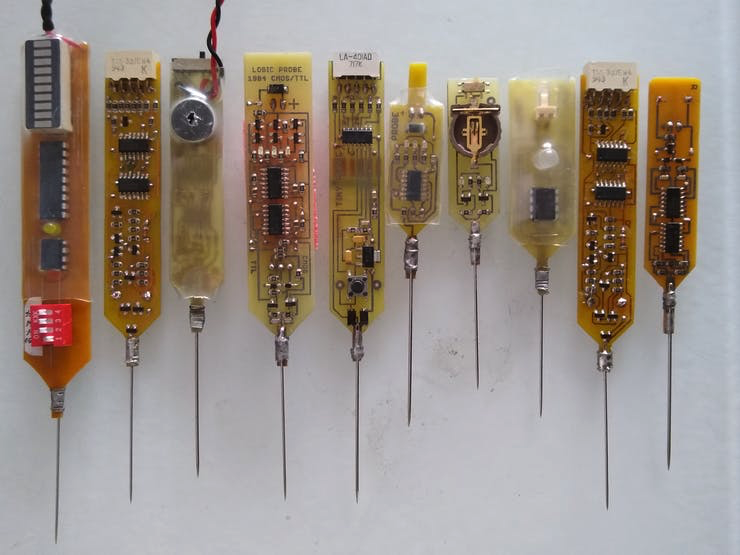
在此之前,作者尝试做过多种不同的逻辑分析探针,看下图是作者多年来设计的一些作品:

作者认为应该设计一款终极的逻辑探针,具有如下的一些特点:
它必须足够小以方便拿在手中
能够显示低、高和不关心的状态
一个显示系统,在使用时易于阅读
对“低”和“高”状态有声音反馈
处理不同逻辑系列的器件,例如:TTL 和 CMOS
能够检测探头是否正在测量快速变化的信号
具有针对意外过电压的输入保护
硬件的设计
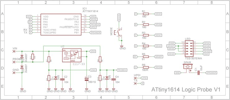
采用了ATtiny1614位微处理器,通过一个7段数码管进行显示测量的电压,并驱动一个扬声器发出声音,轻触开关切换不同的逻辑系列,一个3.3V的稳压器给微处理器提供电源,原理图见下(使用Eagle绘制)

这个设计中用到的器件主要有:
| 微芯科技 ATtiny1614 | x1 |
| TSS-307EWA 7-Seg 0.36in CC 显示器 | x1 |
| LM1117-33 3.3V 稳压器(SOT-223封装) | x1 |
| C&K 开关 PTS 645 系列开关(6mm轴) | x1 |
| SMT-916喇叭 | x1 |
| 3.6V 400mW 齐纳二极管(SOD80C 封装) | x2 |
| 1N4007 – 高电压、高额定电流二极管(SOD-123 包装) | x2 |
| 无源元件:5 个 180R 0805、1 个 91R 0805、2 个 1K 0805、2 个 3K 0805、1 个 15K 0805 电阻器;2 x 0.1uF 0805, 1 x 10uF 0805, 1 x 100uF/10V 7343 电容器 |
作者制作了一个PCB,单面板,主要器件都是表面贴装的。7段数码管和电路板成直角安装。
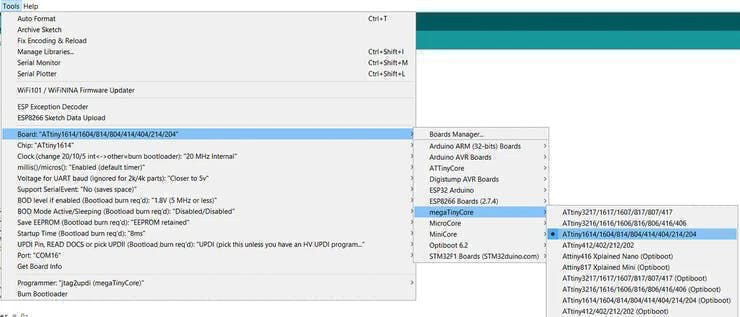
该探针是高度可以配置的,允许添加其它的逻辑系列器件,见下面程序中的截图部分:

下面是制作的PCB,在国外制作PCB还是很不方便的。
将缝衣针绑上做探针:
焊上7段数码管:
装上开关和电源连线:
作者用一个Arduino Nano来对其进行编程:
使用Arduino的IDE:

下面是这个逻辑分析探针的代码:
/************************************************************************** ATtiny1614 Logic Probe Schematic & PCB at https://www.hackster.io/john-bradnam/contact-digital-thermometer-ed18d2 2021-08-10 John Bradnam (jbrad2089@gmail.com) Create program for ATtiny1614 -------------------------------------------------------------------------- Arduino IDE: -------------------------------------------------------------------------- BOARD: ATtiny1614/1604/814/804/414/404/214/204 Chip: ATtiny1614 Clock Speed: 20MHz millis()/micros(): "Enabled (default timer)" Programmer: jtag2updi (megaTinyCore) ATTiny1614 Pins mapped to Ardunio Pins +--------+ VCC + 1 14 + GND (SS) 0 PA4 + 2 13 + PA3 10 (SCK) 1 PA5 + 3 12 + PA2 9 (MISO) (DAC) 2 PA6 + 4 11 + PA1 8 (MOSI) 3 PA7 + 5 10 + PA0 11 (UPDI) (RXD) 4 PB3 + 6 9 + PB0 7 (SCL) (TXD) 5 PB2 + 7 8 + PB1 6 (SDA) +--------+ **************************************************************************/ //Debug mode will use the TX pin to send serial messages. As this is also used//for Segment A, the display is disabled when DEBUG mode is enabled//#define DEBUG //Display Pins#define A_PIN 5 //PB2#define B_PIN 4 //PB3#define C_PIN 3 //PA7#define D_PIN 0 //PA4#define EF_PIN 1 //PA5#define G_PIN 2 //PA6 //Inputs#define VIN_PIN 9 //PA2#define PROBE_PIN 8 //PA1#define MODE_PIN 10 //PA3 #define ADC_PROBE ADC_MUXPOS_AIN1_gc#define ADC_VIN ADC_MUXPOS_AIN2_gc //Outputs#define SPKR_PIN 6 //PB1 //Frequency for different states#define VDD_TONE 1760#define HIGH_TONE 880#define LOW_TONE 220#define GND_TONE 110#define BTN_TONE 440 //Pin and mask mapping tabletypedef struct { int8_t pin; int8_t mask;} SEG; #define SEG_COUNT 6SEG segments[] = { {A_PIN, B00000001}, {B_PIN, B00000010}, {C_PIN, B00000100}, {D_PIN, B00001000}, {EF_PIN, B00010000}, {G_PIN, B00100000}}; //Character set#define CHAR_COUNT 10#define CHAR_SPACE 0#define CHAR_VDD 1#define CHAR_HIGH 2#define CHAR_FLOAT 3#define CHAR_LOW 4#define CHAR_GND 5#define CHAR_PULSE 6#define CHAR_CMOS 7#define CHAR_TTL 8#define CHAR_LS 9 uint8_t charset[] = { B00000000, //CHAR_SPACE B00000001, //CHAR_VDD B00000110, //CHAR_HIGH B00100000, //CHAR_FLOAT B00011111, //CHAR_LOW B00001000, //CHAR_GND B00110011, //CHAR_PULSE B00011001, //CHAR_CMOS B00111000, //CHAR_TTL B00011000 //CHAR_LS}; char debugset[] = { ' ', //CHAR_SPACE '+', //CHAR_VDD '1', //CHAR_HIGH '?', //CHAR_FLOAT '0', //CHAR_LOW '-', //CHAR_GND 'P', //CHAR_PULSE 'C', //CHAR_CMOS 'T', //CHAR_TTL 'L' //CHAR_LS}; typedef struct { float low; //Maximum voltage a LOW state can be (fixed voltage) float high; //Minumum voltage a HIGH state can be as a percentage of VDD uint8_t chr; //Character to display for this family} FAMILY; //This table defines the voltage levels for each family that the probe can measure#define NUMBER_OF_FAMILIES 3FAMILY families[NUMBER_OF_FAMILIES] = { {0.8,80,CHAR_CMOS}, //CMOS family with tones {0.4,48,CHAR_TTL}, //0.4, 2.4 (1987 - National LS S TTL Logic Databook) {0.5,54,CHAR_LS} //0.5, 2.7 (1987 - National LS S TTL Logic Databook)}; enum STATES { STATE_UNKNOWN, STATE_VDD, STATE_HIGH, STATE_FLOAT, STATE_LOW, STATE_GND, STATE_PULSE }; #define PULSE_PERIOD 100 //Maximum time between state changes to be detected as a pulse (1/2 the period => 5Hz) uint8_t activeFamily = 0; //Current chip family being testedSTATES lastState = STATE_UNKNOWN; //Last state measuredSTATES activeState = STATE_UNKNOWN; //Current state at probefloat supplyVoltage = 0; //VDD from 3V3 regulatorfloat probeVoltage = 0; //Last reading from probefloat vinVoltage = 0; //Last reading from VINlong pulseTimeout = 0; //Timer used to measure pulsesbool waitingOnChange = false; //Enabled when waiting on pulseTimeoutbool soundEnabled = false; //Whether tones are played for the states //-------------------------------------------------------------------------// Initialise Hardwarevoid setup(void){ for (int i = 0; i < SEG_COUNT; i++) { pinMode(segments[i].pin, OUTPUT); digitalWrite(segments[i].pin, LOW); } #ifdef DEBUG Serial.begin(115200); #endif pinMode(VIN_PIN, INPUT); pinMode(PROBE_PIN, INPUT); pinMode(MODE_PIN, INPUT_PULLUP); pinMode(SPKR_PIN, OUTPUT); //Setup ADC VREF.CTRLA = VREF_ADC0REFSEL_1V1_gc; ADC0.CTRLC = ADC_REFSEL_VDDREF_gc | ADC_PRESC_DIV256_gc; // 78kHz clock ADC0.CTRLA = ADC_ENABLE_bm; // Single, 10-bit measureSupplyVoltage();} //--------------------------------------------------------------------// Main program loopvoid loop(void){ if (buttonPressed()) { activeFamily++; if (activeFamily == NUMBER_OF_FAMILIES) { activeFamily = 0; soundEnabled = !soundEnabled; //Turn/off audio } showChar(families[activeFamily].chr); noTone(SPKR_PIN); if (soundEnabled) { tone(SPKR_PIN, BTN_TONE); } waitForButtonRelease(); noTone(SPKR_PIN); //Force an update waitingOnChange = false; lastState = STATE_UNKNOWN; } testProbe();} //--------------------------------------------------------------------// Test if button pressedbool buttonPressed(){ bool result = false; if (digitalRead(MODE_PIN) == LOW) { delay(10); //Debounce return (digitalRead(MODE_PIN) == LOW); } return result;} //--------------------------------------------------------------------// Wait until the button is releasedvoid waitForButtonRelease(){ while (digitalRead(MODE_PIN) == LOW) ;} //--------------------------------------------------------------------// Measure the voltages and dislay the results if changedvoid testProbe(){ //Voltages are feed through divide by 4 resistor voltage converter //so they need to multiplied by 4. probeVoltage = measureVoltage(ADC_PROBE) * 4; vinVoltage = measureVoltage(ADC_VIN) * 4; //Calculate HIGH and VDD thresholds from VIN voltage float vdd = vinVoltage - 0.1; float high = families[activeFamily].high * vinVoltage / 100; bool pulse = false; //Workout state if (probeVoltage < 0.1) { activeState = STATE_GND; } else if (probeVoltage <= families[activeFamily].low) { activeState = STATE_LOW; } else if (probeVoltage < high) { activeState = STATE_FLOAT; } else if (probeVoltage <= vdd) { activeState = STATE_HIGH; } else { activeState = STATE_VDD; } if (activeState != lastState) //Only do something if state changes { #ifdef DEBUG Serial.println("p=" + String(probeVoltage) + ", vin=" + String(vinVoltage) + ", vdd=" + String(supplyVoltage)); delay(200); #endif if ((activeState == STATE_HIGH) ^ (lastState == STATE_HIGH)) //Change in state from either LOW to HIGH or HIGH to LOW { pulse = (waitingOnChange && millis() < pulseTimeout); //If state change within PULSE_PERIOD signal it as a pulse pulseTimeout = millis() + PULSE_PERIOD; //Set next timeout waitingOnChange = true; //and signal we are waiting on a state change } else { //This isn't a pulse waitingOnChange = false; pulse = false; } //Turn off any sound from the last state noTone(SPKR_PIN); //Show the result int chr = (pulse) ? CHAR_PULSE : (uint8_t)activeState; showChar(chr); if (soundEnabled) //Play sound if enabled { switch(chr) { case CHAR_VDD: tone(SPKR_PIN, VDD_TONE); break; case CHAR_HIGH: tone(SPKR_PIN, HIGH_TONE); break; case CHAR_LOW: tone(SPKR_PIN, LOW_TONE); break; case CHAR_GND: tone(SPKR_PIN, GND_TONE); break; } } //Record last state lastState = activeState; }} //--------------------------------------------------------------------// Display character on 7 segment display// chr - character to show (0 <= chr < CHAR_COUNT)void showChar(uint8_t chr){ if (chr < CHAR_COUNT) { #ifdef DEBUG Serial.println(debugset[chr]); #else uint8_t mask = charset[chr]; for (int i = 0; i < SEG_COUNT; i++) { digitalWrite(segments[i].pin, (mask & segments[i].mask) ? HIGH : LOW); } #endif } } //--------------------------------------------------------------------------// Measure supply voltage// Source: David Johnson-Davies - www.technoblogy.com - 13th April 2021void measureSupplyVoltage() { ADC0.MUXPOS = ADC_MUXPOS_INTREF_gc; // Measure INTREF ADC0.COMMAND = ADC_STCONV_bm; // Start conversion while (ADC0.COMMAND & ADC_STCONV_bm); // Wait for completion uint16_t adc_reading = ADC0.RES; // ADC conversion result supplyVoltage = 1126.4 / adc_reading;} //--------------------------------------------------------------------------// Measure voltage of a given pin// adcMux - ADC_Ax constant for the pin to measurefloat measureVoltage(uint8_t adcMux) { ADC0.MUXPOS = adcMux; // Measure Analog pin ADC0.COMMAND = ADC_STCONV_bm; // Start conversion while (ADC0.COMMAND & ADC_STCONV_bm); // Wait for completion uint16_t adc_reading = ADC0.RES; // ADC conversion result return supplyVoltage * adc_reading / 1024;}
编辑:jq
-
逻辑分析仪是什么2016-08-23 3643
-
什么是频谱分析仪2019-07-02 2905
-
逻辑分析仪的使用2008-11-27 2791
-
网络分析仪基础2012-01-17 1719
-
音频信号分析仪简介2015-11-13 1325
-
什么是频谱分析仪,频谱分析仪的工作原理是什么,频谱分析仪怎样使用?2017-05-09 17235
-
逻辑分析仪的作用_逻辑分析仪怎么用_逻辑分析仪的使用方法(教程)2017-12-20 55223
-
功率分析仪作用_功率分析仪分类2019-12-19 4517
-
如何选择频谱分析仪和维修频谱分析仪的故障分析2021-02-13 4834
-
逻辑分析仪如何使用 逻辑分析仪使用教程2023-09-19 4621
-
音频分析仪的原理2024-03-29 1703
-
逻辑分析仪可以当示波器用吗2024-07-17 2695
-
Keysight 频谱分析仪(信号分析仪)2024-09-12 1808
-
频谱分析仪与信号分析仪的区别2024-11-27 3302
-
功率分析仪选型_功率分析仪功能2025-01-28 1491
全部0条评论

快来发表一下你的评论吧 !

