

逻辑探针电路图,Logic Probe
电工仪表电路图
描述
逻辑探针电路图,Logic Probe

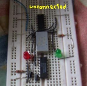
This circuit is a Logic Probe. It indicates the logic state of the node of any TTL logic circuit. To do that, we have to supply the probe with the same power of the circuit that we want to analyse: same Vcc and same GND. To check the logic level, we must connect the "Test" wire of the probe to the desired node of the circuit that we want to check.
If the level is Low, the probe will display a "zero" (0) and only the green LED will be lighted. If the level is High, the probe will display a "one" (1) and only the red LED will be lighted. If the level is Impedance, the probe will display a nothing and no LED will be lighted. The logic level is "Low" when the "Test" wire is connected to the ground of the circuit (the voltage is between 0V and 2V). The logic level is "Impedance" when the "Test" wire is unconnected (it has no voltage or the voltage is between 2V and 3V). The logic level is "High" when the "Test" wire is connected to the positive supply of the circuit (the voltage is between 3V and 5V).

-
深度剖析逻辑探针电路2023-05-18 3571
-
请问有逻辑探针电路图Logic Probe吗?2019-09-10 1656
-
正的逻辑探针电路,Logic Probe Plus2010-04-11 2396
-
开关与逻辑接口电路图2009-07-16 1417
-
音响逻辑电平探头电路图2009-05-19 693
-
经济的ECL逻辑探头电路图2009-04-14 1072
-
CMOS逻辑笔电路图2009-04-07 1688
-
光触发逻辑电路图2009-04-02 1035
-
或逻辑元件构形电路图2008-12-30 1337
-
CMOS逻辑探头电路图2008-12-24 956
-
光电逻辑电路图2008-12-22 1069
全部0条评论

快来发表一下你的评论吧 !
