

The evolution of the RS-232 tr
接口定义
115人已加入
描述
Abstract: RS-232 transceivers have been integral to RS-232 designs for more than two decades. This application note reviews the history of the RS-232 transceiver. It traces technical advances and explains the practical benefits for diverse applications. Various Maxim devices are cited as industry-leading examples of the RS-232 transceiver evolution.
This application note reviews key RS-232 transceiver features. Viewed in chronological order, the evolution of the RS-232 transceiver also reflects changing demands for serial communications.
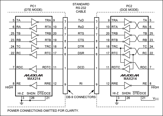
Figure 1. Illustration of a DTE to DCE system. The application features the MAX214 transceiver and shows two PCs with DTE and DCE operation.
Today, RS-232 serial communication is used in applications such as GPS, POS, glucose meters, barcode scanners, automotive telematics, set-top boxes, gaming, and many others that require low-cost, low-speed (sub 1Mbps) serial communication.
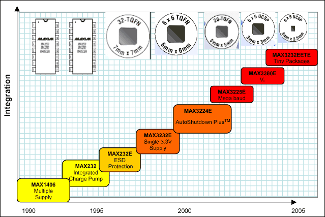
Figure 2. Evolution of the RS-232 transceiver.
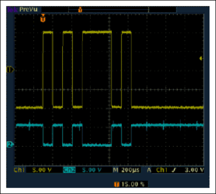
Figure 3. An RS-232 signal. Channel 1 is the bus output signal of the transmitter; Channel 2 is the logic output of the receiver.
In later product generations like the MAX3232, the EIA-232 levels are defined as ±5V into 5kΩ. With a new low-dropout output stage, Maxim introduced RS-232 transceivers with internal charge pumps that provided regulated ±5.5V outputs. This design allows the transmitter outputs to maintain RS-232-compatible levels with a minimum amount of supply current.
How does the integrated charge pump work? The first charge pump works as a voltage doubler and creates +10V from the 5V supply, minus some losses. The second charge-pump converter is configured as an inverter and makes -10V from the +10V, again with some losses. These ±10V power supplies are then used to power the RS-232 transmitters.
The ±15kV ESD-protected RS-232 devices usually have the same pinout and functionality as the standard RS-232 devices, so these parts can be easily substituted without modification to the board layout or footprint. The MAX3232 and the MAX3232E, for example, share the same pinout, package type, and functionality.
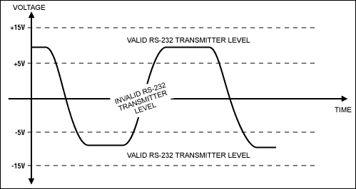
Figure 4. RS-232 output swing levels.
The following discussion reviews some of the special demands for various dual-voltage requirements.
Like the 5V single-supply RS-232 transceivers, the 3.0V to 5.5V devices integrate two charge-pump power supplies. These RS-232 parts are special because of their low-dropout transmitters, which meet the minimum-required ±5V swings, while running from charge-pump power supplies as low as ±5.5V. Consequently, these parts operate from a single 3.0V supply and are still fully compliant with the RS-232 specification. Although these parts run on supplies as low as 3.0V, they are designed to run as high as 5.5V. Therefore, the same part can be used for both 3.3V and 5V designs. Figure 5 shows the MAX3232E 3.3V to 5V RS-232 device.
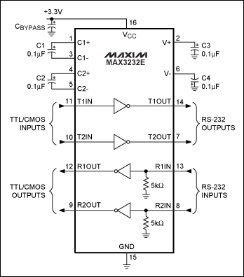
Figure 5. MAX3232E RS-232 transceiver offers integrated charge pumps which allow it to operate from a 3.3V to 5V single supply.
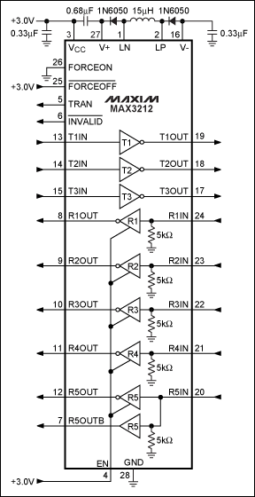
Figure 6. The MAX3212 offers an integrated buck converter which allows the device to operate from a 2.7 V to 3.6V single supply.
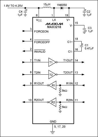
Figure 7. The MAX3218 uses an inductor and charge-pump inverter so the device can operate with 1.8V to 4.25V single power supplies.
AutoShutdown is a power-saving feature. It places the RS-232 device into a low-power shutdown mode whenever it detects that the RS-232 interface is not in use. AutoShutdown is especially powerful because it does not require any processor involvement. Power can be saved without having to make special provisions in software.
AutoShutdown monitors the RS-232 side of the receivers. When connected to another RS-232 device, the receivers will see valid RS-232 signals that are either below -3V or above +3V. If nothing is connected, however, the receivers will typically be at ground. If the AutoShutdown feature detects that all the receivers are between -0.3V and +0.3V for greater than 30µS, it assumes that a valid transmitter is not connected. It automatically puts itself into a low-power mode. See Figures 8 and 10. The transceiver will automatically take itself out of the low-power mode if any one of the receivers' inputs exceeds +2.7V or goes below -2.7V. See Figures 9 and 10.

Figure 8. AutoShutdown is entered if all the receivers' inputs are between ±.3V for at least 30µS.

Figure 9. AutoShutdown is exited if any receiver input exceeds ±2.7V.
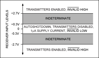
Figure 10. The trip levels for entering and exiting AutoShutdown.
In low-power mode, the transmitters and the charge-pump converters used by the transmitters are turned off. However, because the receivers themselves take very little current to operate, they are kept active. The overall effect is a reduction of quiescent current from .3mA to 1µA typical (1mA to 10µA, max) for the MAX3221. It is important to note that it takes on the order of 100µs for the transmitters to become fully active, once valid RS-232 levels are detected on the receivers. The MAX3221 and MAX3243 are examples of RS-232 devices that offer the AutoShutdown feature.
There are two interesting things to note about AutoShutdown Plus.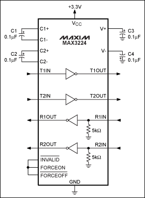
Figure 11. By connecting the ForceOn and ForceOff inputs to the Invalid outputs, an AutoShutdown Plus part can be made to behave like an AutoShutdown part.
The MAX3224E and MAX3245E are examples of RS-232 devices that have the AutoShutdown Plus feature.
In typical RS-232 applications slew rate offers the advantage of minimizing radiated emissions and reflections, but limits the maximum data rate. The slew is a limit that states that the slew rate of a transmitter must be less than 30V/µs. This limit was specified to make RS-232 a simple physical interface. Without this limit, much closer attention must be paid to issues like radiated emissions and some transmission-line effects. Although this slew-rate limit makes the physical interface simpler, it also effectively limits the maximum data rate that can reasonably be used.
Maxim makes parts that are capable of MegaBaud operation and meet the RS-232 specification except for this slew-rate limit. To ensure that the physical interface remains simple, these parts are still slew-rate limited but have a higher limit than allowed in the RS-232 specification (e.g., 150V/µs in the case of the MAX3237E).
What does all of this mean? MegaBaud parts are not strictly RS-232 compliant. If a MegaBaud-capable part is plugged into an ordinary RS-232-compliant port, proper operation cannot be guaranteed even at data rates as low as 20kbps. In reality, however, the lower data rates normally work fine. But operation at 1Mbps is a different story. To guarantee 1Mbps data rates, both ends of the cable must have parts that are capable of MegaBaud operation.
An interesting feature available on some MegaBaud-capable parts is a pin labeled MBAUD. This logic pin configures the part to operate at either an RS-232-compliant slew rate of less than 30V/µs or at a higher slew rate to allow MegaBaud operation. When connected to an ordinary RS-232 port, the part can function in a truly RS-232-compliant mode; when connected to another MegaBaud-capable part, the part can switch gears and transmit at 1Mbps or greater.
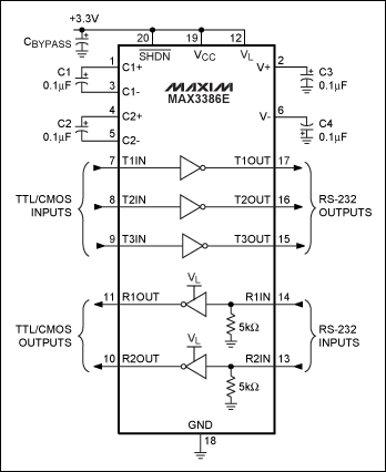
Figure 12. The MAX3386E includes a VL pin that allows the logic thresholds to be programmed for mixed-voltage systems.
Figure 13. A typical 14-bump WLCSP package.
Going forward, RS-232 serial communications will still be used in applications where lower cost and design simplicity are important. In future applications lower supply voltages and higher data rates will be considered for newer designs. Future integration will likely include galvanic isolation and overvoltage protection. One should assume, finally, that Maxim will remain a leader in that innovation.
打开APP阅读更多精彩内容
Introduction
Over the last 25 years, RS-232 transceivers have been modified to address the changing trends in RS-232 designs. Innovations have included integrated charge pumps, high-ESD protection, AutoShutdown™, a 3.3V single supply, higher bandwidth, a level translator, and shrinking packages. These many improvements have enhanced functionality, simplified the RS-232 interface, reduced component count, and saved space. One of the leaders in RS-232 transceiver innovations, Maxim Integrated Products, offers over 158 RS-232 devices with value-added features that address a wide range of applications.This application note reviews key RS-232 transceiver features. Viewed in chronological order, the evolution of the RS-232 transceiver also reflects changing demands for serial communications.
Background
The EIA/TIA-232-E standard was introduced in 1962, and has since been updated four times to meet the evolving needs of serial communication applications. The official name of the EIA/TIA-232-E standard is "Interface Between Data Terminal Equipment (DTE) and Data Circuit-Termination Equipment (CTE) Employing Serial Binary Data Interchange." There is a more simple definition: serial data communication between a host system (DTE) and a peripheral system (CTE) (Figure 1).
Figure 1. Illustration of a DTE to DCE system. The application features the MAX214 transceiver and shows two PCs with DTE and DCE operation.
History of applications
Historically, RS-232 serial communication was used to interface computers to peripherals such as modems, printers, keyboards, joysticks, and a mouse. Most of these applications have now converted to other communication protocols such as the universal serial bus (USB).Today, RS-232 serial communication is used in applications such as GPS, POS, glucose meters, barcode scanners, automotive telematics, set-top boxes, gaming, and many others that require low-cost, low-speed (sub 1Mbps) serial communication.
Evolution of the RS-232 IC design
Although the RS-232 transceiver design has evolved significantly, engineers can still use the RS-232 legacy protocol in today's applications. RS-232 innovations are represented in Figure 2, and discussed in chronological order below.
Figure 2. Evolution of the RS-232 transceiver.
Integrated charge pumps
The original RS-232 IC required two supply rails (+15V and -15V) to provide the appropriate voltages for the RS-232 positive and negative transmitter output swing. (See Figure 3, Channel 1.) In applications where only a single supply was available, an external charge pump was used to double and thus invert the single-supply source. In the late 1980s Maxim integrated a charge pump into the RS-232 transceiver, creating the first RS-232 IC to operate off a single supply, the MAX232. This early generation RS-232 transceiver doubled and inverted the supply voltage to supply the RS-232 transmitter circuitry.
Figure 3. An RS-232 signal. Channel 1 is the bus output signal of the transmitter; Channel 2 is the logic output of the receiver.
In later product generations like the MAX3232, the EIA-232 levels are defined as ±5V into 5kΩ. With a new low-dropout output stage, Maxim introduced RS-232 transceivers with internal charge pumps that provided regulated ±5.5V outputs. This design allows the transmitter outputs to maintain RS-232-compatible levels with a minimum amount of supply current.
How does the integrated charge pump work? The first charge pump works as a voltage doubler and creates +10V from the 5V supply, minus some losses. The second charge-pump converter is configured as an inverter and makes -10V from the +10V, again with some losses. These ±10V power supplies are then used to power the RS-232 transmitters.
High-ESD protection
All RS-232 devices incorporate electro static discharge (ESD) protection on all pins to protect against the ESD (typically ±2kV) encountered during handling and assembly. As handheld and portable equipment adopted RS-232 serial communication, those applications required greater ESD protection against Human Body Model (HBM, for which the industry standard requires greater than ±2kV of ESD protection). Maxim's ESD-protected RS-232 transceivers offer ±15kV ESD per HBM protection on their RS-232 transmitter-output and receiver-input pins. Some devices, such as the MAX3238E, offer the ±15kV ESD protection on both the RS-232 BUS and CMOS pins.The ±15kV ESD-protected RS-232 devices usually have the same pinout and functionality as the standard RS-232 devices, so these parts can be easily substituted without modification to the board layout or footprint. The MAX3232 and the MAX3232E, for example, share the same pinout, package type, and functionality.
Low-voltage operation
Historically, RS-232-compliant parts required a minimum of two supply voltages, one greater than +5V and one less (more negative) than -5V. These two supplies are needed to guarantee the minimum ±5V output swings required for the transmitters. See Figure 4. Systems that already have ±12V supplies can accommodate this power requirement. However, most systems designed today do not have ±12V (or other voltages) available. So to support dual voltages from a single supply, Maxim designed a wide array of transceivers that integrate power-supply converters.
Figure 4. RS-232 output swing levels.
The following discussion reviews some of the special demands for various dual-voltage requirements.
3.0V to 5.5V only
Although 5V single supplies are the most popular RS-232 applications, an increasing number of applications require parts to run from a single 3.3V supply. Operation with 3.3V is important in 3.3V-only systems, but also where the RS-232 parts must interface to 3V logic. Using similar techniques incorporated in the 5V-only parts, Maxim designed transceivers that will run from a single 3.0V to 5.5V supply.Like the 5V single-supply RS-232 transceivers, the 3.0V to 5.5V devices integrate two charge-pump power supplies. These RS-232 parts are special because of their low-dropout transmitters, which meet the minimum-required ±5V swings, while running from charge-pump power supplies as low as ±5.5V. Consequently, these parts operate from a single 3.0V supply and are still fully compliant with the RS-232 specification. Although these parts run on supplies as low as 3.0V, they are designed to run as high as 5.5V. Therefore, the same part can be used for both 3.3V and 5V designs. Figure 5 shows the MAX3232E 3.3V to 5V RS-232 device.

Figure 5. MAX3232E RS-232 transceiver offers integrated charge pumps which allow it to operate from a 3.3V to 5V single supply.
2.7V to 3.6V only
Making RS-232-compliant parts that run below 3.0V requires something other than charge-pump doublers and inverters. Figure 6 shows the MAX3212 which uses a single inductor to generate the ±6.5V required by the transmitters. With this buck converter topology, the part runs on a single supply from 2.7V to 3.6V.
Figure 6. The MAX3212 offers an integrated buck converter which allows the device to operate from a 2.7 V to 3.6V single supply.
1.8V to 4.25V
The MAX3218 (shown in Figure 7) takes a hybrid approach to the voltage-supply problem. It uses an inductor-based solution to generate +6.5V. It then generates -6.5V using a charge-pump inverter. With this technique, the part runs from a 1.8V to 4.25V single supply. This wide input range makes the MAX3218 especially useful for battery-powered systems.
Figure 7. The MAX3218 uses an inductor and charge-pump inverter so the device can operate with 1.8V to 4.25V single power supplies.
AutoShutdown
Many RS-232 devices are used for only small fractions of time. Some glucose meters, for example, typically do not use their RS-232 ports at all. If nothing is connected to the RS-232 port, it makes sense to put the RS-232 part into a low-power mode.AutoShutdown is a power-saving feature. It places the RS-232 device into a low-power shutdown mode whenever it detects that the RS-232 interface is not in use. AutoShutdown is especially powerful because it does not require any processor involvement. Power can be saved without having to make special provisions in software.
AutoShutdown monitors the RS-232 side of the receivers. When connected to another RS-232 device, the receivers will see valid RS-232 signals that are either below -3V or above +3V. If nothing is connected, however, the receivers will typically be at ground. If the AutoShutdown feature detects that all the receivers are between -0.3V and +0.3V for greater than 30µS, it assumes that a valid transmitter is not connected. It automatically puts itself into a low-power mode. See Figures 8 and 10. The transceiver will automatically take itself out of the low-power mode if any one of the receivers' inputs exceeds +2.7V or goes below -2.7V. See Figures 9 and 10.

Figure 8. AutoShutdown is entered if all the receivers' inputs are between ±.3V for at least 30µS.

Figure 9. AutoShutdown is exited if any receiver input exceeds ±2.7V.

Figure 10. The trip levels for entering and exiting AutoShutdown.
In low-power mode, the transmitters and the charge-pump converters used by the transmitters are turned off. However, because the receivers themselves take very little current to operate, they are kept active. The overall effect is a reduction of quiescent current from .3mA to 1µA typical (1mA to 10µA, max) for the MAX3221. It is important to note that it takes on the order of 100µs for the transmitters to become fully active, once valid RS-232 levels are detected on the receivers. The MAX3221 and MAX3243 are examples of RS-232 devices that offer the AutoShutdown feature.
AutoShutdown Plus™
Like the AutoShutdown feature, AutoShutdown Plus is designed to save power by shutting the RS-232 device down whenever it is not being used. However, AutoShutdown Plus will shut itself down whenever there is no activity on the signals for 30 seconds. This operation is intended for applications where a transceiver is connected to the RS-232 port, but is not sending data.There are two interesting things to note about AutoShutdown Plus.
- It monitors both the receivers and the transmitters for activity.
- It can be made to behave like AutoShutdown if the Invalid line is tied to both ForceOn and ForceOff. See Figure 11.

Figure 11. By connecting the ForceOn and ForceOff inputs to the Invalid outputs, an AutoShutdown Plus part can be made to behave like an AutoShutdown part.
The MAX3224E and MAX3245E are examples of RS-232 devices that have the AutoShutdown Plus feature.
MegaBaud™
In applications where higher bandwidth is required over lower radiated emissions, MegaBaud RS-232 devices are an ideal solution. MegaBaud is Maxim's term for RS-232 logic-level-compatible data rates that are 1Mbps or higher. Note that the term "compatible" is used here, not "compliant," because the MegaBaud function actually violates the RS-232 slew-rate-limit specification.In typical RS-232 applications slew rate offers the advantage of minimizing radiated emissions and reflections, but limits the maximum data rate. The slew is a limit that states that the slew rate of a transmitter must be less than 30V/µs. This limit was specified to make RS-232 a simple physical interface. Without this limit, much closer attention must be paid to issues like radiated emissions and some transmission-line effects. Although this slew-rate limit makes the physical interface simpler, it also effectively limits the maximum data rate that can reasonably be used.
Maxim makes parts that are capable of MegaBaud operation and meet the RS-232 specification except for this slew-rate limit. To ensure that the physical interface remains simple, these parts are still slew-rate limited but have a higher limit than allowed in the RS-232 specification (e.g., 150V/µs in the case of the MAX3237E).
What does all of this mean? MegaBaud parts are not strictly RS-232 compliant. If a MegaBaud-capable part is plugged into an ordinary RS-232-compliant port, proper operation cannot be guaranteed even at data rates as low as 20kbps. In reality, however, the lower data rates normally work fine. But operation at 1Mbps is a different story. To guarantee 1Mbps data rates, both ends of the cable must have parts that are capable of MegaBaud operation.
An interesting feature available on some MegaBaud-capable parts is a pin labeled MBAUD. This logic pin configures the part to operate at either an RS-232-compliant slew rate of less than 30V/µs or at a higher slew rate to allow MegaBaud operation. When connected to an ordinary RS-232 port, the part can function in a truly RS-232-compliant mode; when connected to another MegaBaud-capable part, the part can switch gears and transmit at 1Mbps or greater.
VL pins
In most modern applications, the microcontroller (µC) operates at much lower supply than the transceivers. Thus, logic-level translators are typically used to interface between the µC and the RS-232 transceiver's logic signals. Some RS-232 devices integrate a level translator, such as the MAX3386E which offers a VL pin to program logic thresholds on the receiver outputs and the transmitter inputs. This flexibility becomes valuable in systems with multiple supply voltages and/or multiple logic levels. For example, the MAX3386E in Figure 12 runs at a 3.0V to 5.5V single supply and the VL pin sets the logic thresholds between 0.8V to 5V.
Figure 12. The MAX3386E includes a VL pin that allows the logic thresholds to be programmed for mixed-voltage systems.
Tiny packages
As most modern applications are design to fit into small housings, the ICs must also fit into a very small board area. One the smallest packages available is the chip-scale package (CSP). The wafer-level chip-scale package (WLCSP) is designed for the IC to attach to the printed-circuit board face-down; the chip's pads connect to the PC board's pads through individual solder balls without needing any underfill material (Figure 13). WLCSP technology differs from other ball-grid array, leaded, and laminate based CSPs because there are no bond wires or interposer connections. The principle advantage of the WLCSP is that the IC-to-PC board inductance is minimized. Secondary benefits are reduction in package size and manufacturing cycle time, and enhanced thermal conduction characteristics. Maxim's WLCSP is trademarked as UCSP™.Figure 13. A typical 14-bump WLCSP package.
Conclusion
RS-232 technology has evolved steadily in accordance with application demands over the last 25 years. Maxim's many RS-232 transceivers are evidence of the important advances made in the industry. There is, moreover, no reason to assume that design enhancements will not continue.Going forward, RS-232 serial communications will still be used in applications where lower cost and design simplicity are important. In future applications lower supply voltages and higher data rates will be considered for newer designs. Future integration will likely include galvanic isolation and overvoltage protection. One should assume, finally, that Maxim will remain a leader in that innovation.
声明:本文内容及配图由入驻作者撰写或者入驻合作网站授权转载。文章观点仅代表作者本人,不代表电子发烧友网立场。文章及其配图仅供工程师学习之用,如有内容侵权或者其他违规问题,请联系本站处理。
举报投诉
- 相关推荐
- 热点推荐
- RS-232
-
RS-232和RS-485之间的区别2024-04-16 5434
-
选择和使用RS-232、RS-422和RS-485串行数据标准的指南2023-03-28 4801
-
RS-232和RS-485的区别2022-10-30 42654
-
基于RS-232的数据采集系统设计2017-04-20 2059
-
RS-232/UART Triggering and Har2010-08-05 1253
-
DID/RS-232,DID/RS-232是什么意思2010-03-27 1724
-
RS-232 接口,RS-232 接口是什么意思2010-03-09 61945
-
iCoupler Isolation in RS-232 A2009-06-21 1132
-
RS-232接口功能的解释-RS-232 Features2009-04-24 4073
-
简单的RS-232测试电路2009-02-12 1712
-
RS-232 Transceivers Deliver Hi2009-01-23 1198
-
RS-232标准介绍2008-10-21 5163
全部0条评论

快来发表一下你的评论吧 !

