
GMSL line-fault detection
汽车电子
2433人已加入
描述
This application note describes an easy way to detect serial-link line faults (e.g., line shorts) in serializer/deserializer (SerDes) applications. The approach described here uses the serializer's built-in monitoring circuit, an external n-channel MOSFET, and a resistor network. The MAX9259 gigabit multimedia serial link (GMSL) is featured.
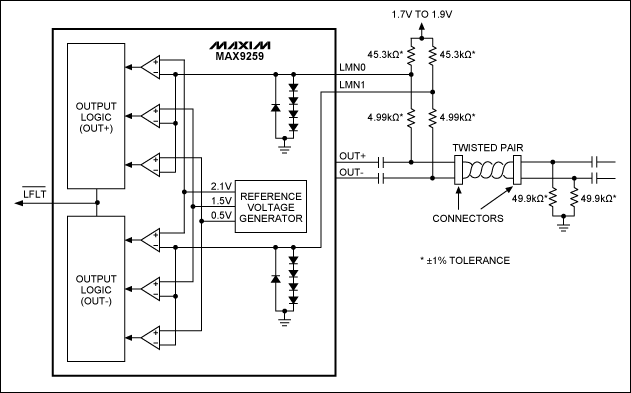
The MAX9259 has a built-in line-fault monitor to detect serial link failures, such as line shorts to the power supply (battery), shorts to ground, or open lines. Figure 1 shows the original circuit and the required external resistors, as depicted in the MAX9259 data sheet.

Figure 1. Original line-fault detection circuit featuring the MAX9259 serializer.
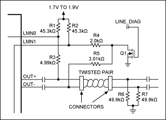
With two extra components, the line-fault monitor's coverage can be extended to also detect a short circuit of the twisted-pair cable (Figure 2).

Figure 2. Line-fault detection circuit provides short-circuit detection.
The new, enhanced circuit (Figure 2) splits the 4.99kΩ resistor into two; one resistor is 2.0kΩ (R4) and the other is 3.01kΩ (R5). An n-channel MOSFET (Q1) is added as a switch. The drain of Q1 connects to the node between R4 and R5. The source of Q1 is tied to ground.
When the signal LINE_DIAG (connected to the gate of Q1) transitions low, Q1 is turned off. This new circuit function is exactly the same as the original circuit shown in Figure 1, but adds short-circuit detection of the twisted-pair cable.
When LINE_DIAG transitions high, Q1 is turned on and connects the node between R4 and R5 to the ground.
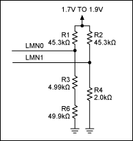
If there is no short between the two wires of the twisted-pair cable, Q1 connects the node between R4 and R5 to ground. The resulting circuit, Figure 3, is a simplified version of Figure 2.
Under this condition, only the level of LMN1 is affected by the Q1. The voltage of LMN0 is still at its normal level. However, with the supply voltage between 1.7V and 1.9V, the voltage of LMN1 now becomes low enough to detect a short-to-ground condition. As a result, the MAX9259 active-low LFLT output transitions low; the register 0x08 bits D[1:0] read as LFPOS = 10 (normal) and bits D[3:2] read as LFNEG = 01 (short-to-ground).

Figure 3. No short circuit.

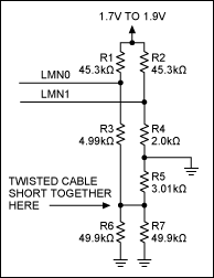
Figure 4. Short circuit detected.
When the two wires in a twisted-pair cable are shorted together, the circuit of Figure 2 becomes equivalent to the one displayed in Figure 4. Q1 connects the same node to ground, but since the twisted-pair cable is shorted, it affects the voltage level of LMN0.
With a supply voltage of 1.7V to 1.9V, the voltage for LMN0 and LMN1 will be below the 0.3V maximum short-to-ground threshold listed in the MAX9259 data sheet. As a result, the MAX9259's active-low LFLT output transitions low, the register 0x08 bits D[1:0] read as LFPOS = 01 (short-to-ground), and bits D[3:2] read as LFNEG = 01 (short-to-ground).
MOSFET leakage current (zero gate voltage drain current, IDSS) is an important factor for proper operation of the circuit described in Figure 2. Each microamp (µA) of MOSFET leakage current will bring the voltage of LMN1 down by 1µA × 45.3kΩ = 45.3mV when the cable is open, and by 1µA × (47.3kΩ//52.91kΩ) = 25mV during normal operation mode. Excess voltage drop on LMN1 can trigger false fault detections. A MOSFET with low IDSS (like the ON Semiconductor® BS107 with IDSS = 30nA, max) should be used as the switch for this application.
Equally important is the matching of the resistor pair. For the circuit displayed in Figure 2, R1 should be equal to R2, R3 should be equal to R4 + R5, and R6 should be equal to R7.
Please refer to the MAX9259 data sheet for detailed information about the internal register and the line-fault threshold values of LMN0 and LMN1.
打开APP阅读更多精彩内容
The MAX9259 has a built-in line-fault monitor to detect serial link failures, such as line shorts to the power supply (battery), shorts to ground, or open lines. Figure 1 shows the original circuit and the required external resistors, as depicted in the MAX9259 data sheet.

Figure 1. Original line-fault detection circuit featuring the MAX9259 serializer.
With two extra components, the line-fault monitor's coverage can be extended to also detect a short circuit of the twisted-pair cable (Figure 2).

Figure 2. Line-fault detection circuit provides short-circuit detection.
The new, enhanced circuit (Figure 2) splits the 4.99kΩ resistor into two; one resistor is 2.0kΩ (R4) and the other is 3.01kΩ (R5). An n-channel MOSFET (Q1) is added as a switch. The drain of Q1 connects to the node between R4 and R5. The source of Q1 is tied to ground.
When the signal LINE_DIAG (connected to the gate of Q1) transitions low, Q1 is turned off. This new circuit function is exactly the same as the original circuit shown in Figure 1, but adds short-circuit detection of the twisted-pair cable.
When LINE_DIAG transitions high, Q1 is turned on and connects the node between R4 and R5 to the ground.
If there is no short between the two wires of the twisted-pair cable, Q1 connects the node between R4 and R5 to ground. The resulting circuit, Figure 3, is a simplified version of Figure 2.
Under this condition, only the level of LMN1 is affected by the Q1. The voltage of LMN0 is still at its normal level. However, with the supply voltage between 1.7V and 1.9V, the voltage of LMN1 now becomes low enough to detect a short-to-ground condition. As a result, the MAX9259 active-low LFLT output transitions low; the register 0x08 bits D[1:0] read as LFPOS = 10 (normal) and bits D[3:2] read as LFNEG = 01 (short-to-ground).

Figure 3. No short circuit.

Figure 4. Short circuit detected.
When the two wires in a twisted-pair cable are shorted together, the circuit of Figure 2 becomes equivalent to the one displayed in Figure 4. Q1 connects the same node to ground, but since the twisted-pair cable is shorted, it affects the voltage level of LMN0.
With a supply voltage of 1.7V to 1.9V, the voltage for LMN0 and LMN1 will be below the 0.3V maximum short-to-ground threshold listed in the MAX9259 data sheet. As a result, the MAX9259's active-low LFLT output transitions low, the register 0x08 bits D[1:0] read as LFPOS = 01 (short-to-ground), and bits D[3:2] read as LFNEG = 01 (short-to-ground).
MOSFET leakage current (zero gate voltage drain current, IDSS) is an important factor for proper operation of the circuit described in Figure 2. Each microamp (µA) of MOSFET leakage current will bring the voltage of LMN1 down by 1µA × 45.3kΩ = 45.3mV when the cable is open, and by 1µA × (47.3kΩ//52.91kΩ) = 25mV during normal operation mode. Excess voltage drop on LMN1 can trigger false fault detections. A MOSFET with low IDSS (like the ON Semiconductor® BS107 with IDSS = 30nA, max) should be used as the switch for this application.
Equally important is the matching of the resistor pair. For the circuit displayed in Figure 2, R1 should be equal to R2, R3 should be equal to R4 + R5, and R6 should be equal to R7.
Please refer to the MAX9259 data sheet for detailed information about the internal register and the line-fault threshold values of LMN0 and LMN1.
声明:本文内容及配图由入驻作者撰写或者入驻合作网站授权转载。文章观点仅代表作者本人,不代表电子发烧友网立场。文章及其配图仅供工程师学习之用,如有内容侵权或者其他违规问题,请联系本站处理。
举报投诉
- 相关推荐
- 热点推荐
- GMSL
-
GMSL将不再单独演进:为什么行业领导者都选择共建OpenGMSL?2025-06-17 508
-
满足GMSL静电防护要求的方案2024-07-09 1281
-
gmsl和lvds差异2023-12-08 10174
-
MAX33011E-MAX33015E: +5V, 5Mbps CAN Transceiver with ±65V Fault Protection, Fault Detection and Reporting, ±25V CMR, and ±40kV ESD Protectio2023-10-17 27
-
MAX16826: Programmable, Four-String HB LED Driver with Output-Voltage Optimization and Fault Detection Data Sheet MAX16826: Programmable, Fo2023-10-16 27
-
MAX9240A: 6.25MHz to 100MHz, 25-Bit GMSL Deserializer for Coax or STP Cable with Line Fault Detect Data Sheet MAX9240A: 6.25MHz to 100MHz, 22023-10-12 21
-
DAC,COMP,HRTIM Fault功能的使用2023-09-19 679
-
使用STM32 HRTIM的Fault事件做输出保护2023-09-09 5124
-
UG-1887: Evaluating the ADG5421F ±60 V Fault Protection and Detection, 11 Ω RON, Dual SPST Switch2021-01-29 583
-
NB3000_Edge_Detection2016-02-18 1125
-
HRTIMER的多种Fault事件联动机制2015-12-07 505
-
Fault-Tolerant Analog Switches2009-04-20 1031
全部0条评论

快来发表一下你的评论吧 !

