

How to make the DS34S132 TDM-o
通信设计应用
描述
How to make the DS34S132 TDM-over-Packet (TDMoP) IC interoperable with other vendors' TDMoP devices
Interoperability is the ability of a system to work with other vendors' systems with little or no intervention from the system operator. The interoperability of systems makes it possible to provide services to, and accept services from, other systems. It enables different vendors' systems to operate properly together. This application note explains how the DS34S132 TDM-over-Packet (TDMoP) IC can be set up to provide interoperability with any other vendor's TDMoP device.
Introduction
It is no secret that today's communications require ever more complex interactions among systems and components. It is within this context that interoperability assumes greater importance with each technological advance. Interoperability is the ability of a system to work with other vendors' systems with little or no intervention from the system operator. The interoperability of systems makes it possible to provide services to, and accept services from, other systems. It enables different vendors' systems to operate properly together.
This application note focuses on the Maxim TDM-over-Packet (TDMoP) IC, the DS34S132. The article explains the setup requirements to provide interoperability between the DS34S132 and other vendors' TDMoP devices.
Requirements for interoperability
The packet stream created by Maxim's TDMoP devices may not have the same packet header information as other vendors' TDMoP devices. To make TDMoP devices interoperable, the user needs to know the device's setup type. The setup for a Maxim device will be one of the following:
- IP/UDP/RTP/SAToP
- IP/UDP/RTP/CESoPSN
- MEF/RTP/CESoETH—unstructured (i.e., MEF/SAToP)
- MEF/RTP/CESoETH—structured locked (i.e., MEF/CESoPSN)
- MPLS/RTP/SAToP—unstructured (i.e., MPLS/RTP/SAToP)
- MPLS/RTP/CESoPSN—structured locked (i.e., MPLS/RTP/CESoPSN)
Each TDMoP device setup has different packet headers. To be interoperable, the packet header from Maxim TDMoP devices must be formatted the same as the packet header from other vendors' devices. This means that the user needs to compare the packet headers for the TDMoP devices and look for format differences. This application note shows how to modify packet header values for the DS34S132 TDMoP device by using the Maxim user application. It also explains how to change the Maxim bundle configuration to accept packets with same protocol but different header information.
TDMoP format
This section shows the functional description for the TDM-over-Packet module. To transport TDM data through packet-switched networks, the TDMoP device encapsulates TDM data into Ethernet packets, as depicted in Figure 1. The descriptions for different blocks of the TDMoP headers are given in Table 1.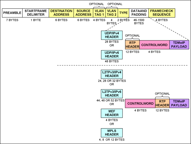
Figure 1. TDMoP encapsulation in an Ethernet packet.
Table 1. Ethernet packet structure
| Field | Description |
| Preamble | A sequence of 56 bits (alternating 1 and 0 values) used for synchronization. Gives components in the network time to detect the presence of a signal. |
| Start frame delimiter | A sequence of 8 bits (10101011) that indicates the start of the packet. |
| Destination and Source Addresses | The Destination Address field identifies the station or stations that are to receive the packet. The Source Address identifies the station that originated the packet. A Destination Address can specify either an "individual address" destined for a single station, or a "multicast address" destined for a group of stations. A Destination Address of all 1 bits refers to all stations on the LAN and is called a "broadcast address." |
| Type | Ether type |
| Data and padding | This field contains the data transferred from the source station to the destination station or stations. The maximum size of this field is 1500 bytes. A minimum size Ethernet packet is 64 bytes from the Destination Address field through the Frame Check Sequence. If the packet size of this field is less than 46 bytes, padding is used to bring the packet size up to the minimum length. |
| Frame check sequence | This field contains a 4-byte cyclical redundancy check (CRC) value used for error checking. When a source station assembles a packet, it performs a CRC calculation on all the bits in the packet from the Destination Address through the pad fields (that is, all fields except the preamble, start frame delimiter, and Frame Check Sequence). The source station stores the value in this field and transmits it as part of the packet. When the destination station receives the packet, it performs an identical check. If the calculated value does not match the value in this field, the destination station assumes that an error has occurred during transmission and discards the packet. |
The user needs to concentrate on two sections of the TDMoP headers for interoperability:
- UDP/IPv4 header for interoperability
- RTP header for interoperability
UDP/IPv4 header for interoperability
Figure 2 shows the UDP/IPv4 header structure. Tables 2 and 3 describe the different fields of IPv4 and UDP Header structures.
Figure 2. UDP/IPv4 header.
Table 2. IPv4 Header structure
| Field | Description |
| IPVER | IP version number; IPv4 IPVER = 4 |
| IHL | Length in 32-bit words of the IP Header, IHL = 5 |
| IP TOS | IP type of service |
| Total length | Length in octets of IP Header and data |
| Identification | IP fragmentation identification |
| Flags | IP control flags; must be set to 010 to avoid fragmentation |
| Fragment offset | Indicates where in the datagram the fragment belongs; not used for TDMoP |
| Time to live | IP time-to-live field; datagrams with zero in this field are discarded |
| Protocol | Must be set to 0x11 to signify UDP |
| IP Header checksum | Checksum for the IP Header |
| Source IP address | IP address of the source |
| Destination IP address | IP address of the destination |
Table 3. UDP Header structure
| Field | Description |
| Source port number, destination port number | Either the source or the destination port number holds the bundle identifier. The unused field can be set to 0x85E (2142), which is the user's port number assigned to TDMoP by the Internet Assigned Numbers Authority (IANA). For UDP/IP-specific OAM packets, the bundle identifier is all 1s. |
| UDP length | Length in octets of UDP Header and data |
| UDP checksum | Checksum of UDP/IP Header and data. If not computed, it must be set to zero. |
According to IANA, the Destination Port of the UDP Header should be set to 0x85E (2142), which is the user's port number assigned to TDMoP. Maxim TDMoP devices follow this regulation by default.
Some of the TDMoP vendors assign a bundle identifier at the Destination Port number location instead of at source port number location inside the UDP header. Some of the vendors also assign random numbers as a user port number rather than 0x85E, which is assigned by IANA. The user can resolve these issues in two ways with the DS34S132.
- Assign all the bundle identifier to the desired location in the preconfiguration menu.
- Indicate to the bundle engine where to expect the bundle identifier in the incoming packets.
- Assigning all the bundle identifier to desired location in the preconfiguration menuThe preconfiguration menus for DS34S132 are shown in Figure 3.
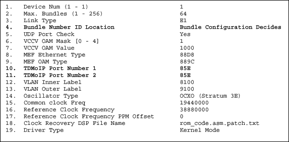
Figure 3. Preconfiguration menu of DS34S132.
Item 4, Bundle Number ID Location, indicates where to find the bundle identifier. If the user selects this menu, then the following options will appear (Figure 4).
Figure 4. Option 4 from preconfiguration menu of the DS34S132.
Option 3 from Figure 4, Bundle in DST UDP PORT, will assign a bundle identifier to Destination Port number location in UDP Header. Option 4, Bundle in SRC UDP PORT, will assign a bundle identifier to source port number location in UDP Header.
So, after identifying the incoming packets' bundle identifier location, the user can assign their own bundle identifier in the appropriate location.
To assign random numbers as a user port number rather than 0x85E, which is assigned by IANA, the user can choose to change option 10 and 11 from the preconfiguration menu.
- Indicate to the bundle engine where to expect the bundle identifier in the incoming packets.Referring back to Figure 4, option 1, Bundle Configuration Decides (BCDR4), will assign a bundle identifier either in the Destination Port number or in source port number location, based on the user's Bundle Configuration which is shown in Figure 5.
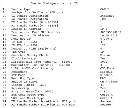
Figure 5. Bundle Configuration menu of DS34S132.
In the above Bundle Configuration menu, the user is inserting a bundle identifier number in UDP source port number location. The user is also indicating that the packet classifier should expect the bundle identifier of the incoming packet in the UDP source port number location.
If the user knows that the incoming packet's bundle identifier is in a UDP Destination Port number location, then s/he can easily indicate it by changing the option 45, RX Bundle Number Location at UDP port, to Destination as shown in Figure 6.
Figure 6. Option 45 from the Bundle Configuration menu of the DS34S132.
RTP Header for interoperability
Figure 7 shows the RTP Header structure and Table 4 describes the different fields of the RTP Header structures.
RTP Header

Figure 7. RTP Header.
Table 4. RTP Header structure
| Field | Description |
| V | RTP version; must be set to 2. |
| P | Padding bit; must be set to 0. |
| X | Extension bit; must be set to 0. |
| CC | CSRC count; must be set to 0. |
| M | Marker bit; must be set to 0. |
| PT | Payload type. One PT value MUST be allocated from the range of dynamic values for each direction of the bundle. The same PT value MAY be reused for both directions of the bundle, and is also reused between different bundles. |
| SN | The sequence number identical to the sequence number in the control word. |
| TS | Timestamp. The RTP Header can be used in conjunction with the following modes of timestamp generation: Absolute mode: the chip sets timestamps using the clock recovered from the incoming TDM circuit. Differential (common clock) mode: The two chips at bundle edges have access to the same high-quality clock source, and this clock source is used for timestamp generation. |
| SSRC | Identifies the synchronization source. This identifier should be chosen randomly, with the intent that no two synchronization sources within the same RTP session will have the same SSRC identifier. |
To generate a timestamp in Absolute Clock Recovery mode, RTP Generator Timestamp Mode Select (TSGMS) bit of Port Receive Configuration Register 4 (PRCR4) needs to be set to 1, i.e., PRCR4.TSGMS = 1. To generate a timestamp in Differential Clock Recovery mode, TSGMS bit PRCR4 register needs to be set to 0, i.e., PRCR4.TSGMS = 0. The user does not need to set these register bits manually. When the RTP is enabled in the bundle configuration, then these bits are set.
In adaptive mode, the clock recovery algorithm in Maxim's DS34S132 TDMoP device recovers the clock based on the interpacket arrival time delay. So enabling RTP in the adaptive mode is optional in Adaptive Clock Recovery mode. However, in Differential mode, the clock recovery algorithm in Maxim's DS34S132 TDMoP device recovers the clock based on the analysis of the timestamp in the RTP Header. So enabling RTP is mandatory in Differential Clock Recovery mode.
To be interoperable, the user needs to determine the mode that the other TDMoP vendors are using to generate a timestamp in the RTP Header. The user also needs to know whether the other system is in Adaptive or Differential Clock Recovery mode. The clock recovery mode can be changed on a per-port basis in the interface configuration. Figure 8 shows how to change the clock-recovery mode. By default, it comes as Adaptive mode per port.
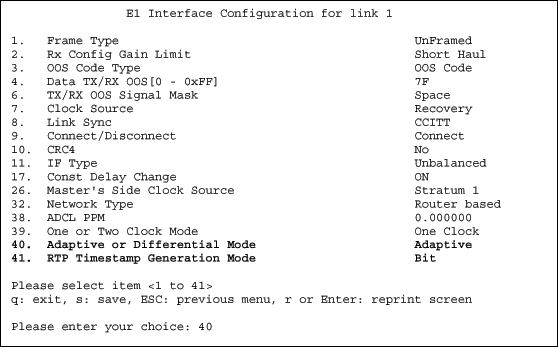
Figure 8. Interface configuration.
Now if the user wants to change the clock-recovery mode, then s/he needs to use option 40, Adaptive or Differential mode, as shown in Figure 9.

Figure 9. Selecting Differential Clock Recovery mode in interface configuration.
Unlike Maxim's TDMoP devices, some of the TDMoP vendors recover the clock based on the timestamp in the RTP header either in Adaptive or Differential Clock Recovery mode. So, to be interoperable with those vendors' system, the Maxim TDMoP devices need to enable RTP in Adaptive Clock Recovery mode. The DS34S132, as well as other TDMoP vendor's devices, can generate a timestamp in the RTP Header in three ways:
- Bit mode
- Byte mode
- Frame mode
Whether the packet is in Adaptive Clock Recovery mode or in Differential Clock Recovery mode, the user then can generate a timestamp in the RTP Header by changing the interface and Bundle Configuration, as shown in Figure 10.
Figure 10. Selecting Bit, Byte, or Frame mode for timestamp in interface configuration.
Once the selection of clock recovery mode and Timestamp generation mode is done in the interface configuration, then the user needs to enable RTP mode in the Bundle Configuration. Previously, Figure 5 showed the Bundle Configuration with RTP mode disabled. From this Bundle Configuration menu, the user needs to use option 27 to enable RTP mode, as shown in Figure 11.
Figure 11. Selecting Bit, Byte, or Frame mode for a timestamp in interface configuration.
Once the RTP mode is enabled, then the Bundle Configuration menu will look like Figure 12.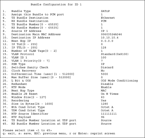
Figure 12. Bundle Configuration menu after enabling RTP mode.
How to distinguish the packet contents from other vendors' TDMoP devices
There are different kinds of software for analyzing the packet headers on the Ethernet. Wireshark® software was used for this application note. The freeware is available for download. For more information about Wireshark, please use the Frequently Asked Questions sections from the website.
Conclusion
Interoperability refers to the ability of diverse systems and organizations to work together seamlessly. Products achieve interoperability either by adhering to published interface standards, or by allowing configuration changes that convert one product's interface into another product's interface "on the fly". By knowing the contents of the packets generated by other TDMoP devices, Maxim devices can be configured easily to match the packet configurations of other TDMoP devices.
If you have questions about TDMoP products or any other Maxim telecom products, then please join our Member Center.
After completing the membership sign-up process, please submit your support request online via the technical support request form.
-
如何使DS34S132 TDM包IC与其他厂商的TDMoP器件互操作2023-02-21 1920
-
DS34S132GNA2+ 接口 - 电信2023-01-15 96
-
DS34S132GN+ 接口 - 电信2023-01-14 64
-
DS34S102GN+ DS34S102GN+ - (Maxim Integrated) - 专用 IC2022-11-16 79
-
如何实现DS34S132与TDMOP器件的互操作2020-12-04 798
-
如何实现DS34S132与DDR3存储器的对接2018-11-26 2941
-
DS34S132 32路独立TDM端口2011-09-27 1790
-
DS34S132使用DDR3内存模块应用笔记2011-08-29 1192
-
DS34S132与TDMoP器件互操作的实现2011-04-18 2274
-
如何实现DS34S132与其它TDMoP器件的互操作2011-03-20 1983
-
DS34S132,pdf datasheet (32-Por2009-07-25 697
-
Maxim的TDM-over-Packet (TDMoP)设2009-04-20 2474
-
DS34S101, DS34S102, DS34S104,2008-08-10 2201
全部0条评论

快来发表一下你的评论吧 !

