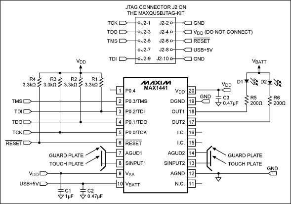

MAX1441应用电路和USB JTAG接口连接电路
IC应用电路图
505人已加入
描述
MAX1441应用电路和USB JTAG接口连接电路
shows an application circuit with the connections between the MAX1441 and the JTAG interface on a MAXQUSBJTAG-KIT board. Please note that in this schematic, pullup resistors which are required on the JTAG lines are part of the application circuit. Typically, pullup resistors are part of the test system and there is no need for duplication on the application board.
Figure 1. JTAG interface connections between a MAX1441 application circuit and the MAXQUSBJTAG-KIT board.
声明:本文内容及配图由入驻作者撰写或者入驻合作网站授权转载。文章观点仅代表作者本人,不代表电子发烧友网立场。文章及其配图仅供工程师学习之用,如有内容侵权或者其他违规问题,请联系本站处理。
举报投诉
- 相关推荐
- 热点推荐
- MAX1441
-
MAX1441双通道接近检测与触摸屏传感器的SPI接口设计指南2023-06-25 1193
-
利用USB至JTAG接口板编程MAX14412023-02-09 1574
-
使用USB转JTAG接口板对MAX1441进行编程2023-01-14 2573
-
接近式和触摸传感器芯片MAX1441的性能特点及应用分析2021-05-05 3394
-
解析:MAX1441应用电路与JTAG接口板连接2012-05-15 3339
-
MAX1441与触摸屏传感器的SPI接口设计指南2012-04-09 2515
-
MAX1441接近和触摸传感器编程器用户手册2011-12-22 966
-
USB至JTAG接口板与MAX1441应用电路的连接2011-01-19 875
-
Programming the MAX1441 with a2010-09-13 1557
-
MAX1441 用于无源RKE系统的单芯片接近检测/触摸传感2010-09-05 1674
-
MAX1441,pdf (Automotive, Two-C2010-07-20 641
-
RJ45接口与串口连接电路图2009-11-13 14289
全部0条评论

快来发表一下你的评论吧 !

