

在gazebo中搭建仿真场景需要哪些内容
描述
本篇在gazebo中搭建可以模拟产生livox_camera_lidar_calibration功能包需要的数据的仿真场景.
场景搭建要求
下面总结下,针对livox_camera_lidar_calibration功能包仿真都需要哪些内容:
livox 激光雷达,可以产生livox激光雷达这种的固态雷达的数据
相机,生成图像
棋盘标定板
矩形标定板
激光雷达和相机可以一起改变角度和位置(世界坐标系下)
这个场景要求想起了之前搭建的一个无人机和云台,那么在上面再装一个livox avia 和 一个 carema就OK了
云台装在一个无人机上,刚好可以移动及改变 雷达和相机的姿态.
场景搭建
创建一个云台挂在无人机上
这个是之前搭建好的,不重点说了,直接上图,就是下面这个样子
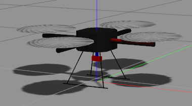
其中无人机和云台的尺寸比较小,和livox和camera的比例不太一致,不过仿真就不那么追求完美了,可以用就行.
云台是这样的:
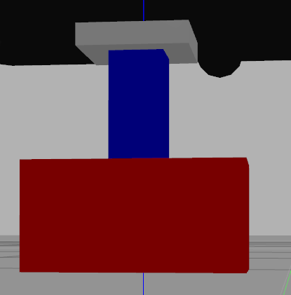
灰色的是云台的gimbal_base_link,用于与无人机的连接,连接方式是固定的,所以云台的航向是完全锁定机头方向的
<joint name="${name}_joint" type="fixed"> <parent link="${parent}"/> <child link="gimbal_base_link"/> <origin xyz="0 0 -0.05" rpy="${M_PI} 0 ${M_PI/2} " /> <axis xyz="0 0 1" /> </joint>
蓝色的是link1,向下延伸杆.与gimbal_base_link为固定连接.
红色的是云台平台的主体link2 , 与link1, 连接一个joint,用于俯仰的控制
<joint name="swivel_J1" type="revolute"> <parent link="link_1"/> <child link="link_2"/> <origin xyz="0 0 ${SizeGain*0.01}" rpy="0 0 0" /> <axis xyz="1 0 0" /> <limit lower="-1.745" upper="2.356" effort="10" velocity="1.0" /> <joint_properties damping="0" friction="0"/> </joint> <transmission name="tran2"> <type>transmission_interface/SimpleTransmission</type> <joint name="swivel_J1"> <hardwareInterface>hardware_interface/EffortJointInterface</hardwareInterface> </joint> <actuator name="motor2"> <hardwareInterface>hardware_interface/EffortJointInterface</hardwareInterface> <mechanicalReduction>1</mechanicalReduction> </actuator> </transmission>
创建一个livox 和camera 挂在云台上
上面说了尺寸问题,为了避免数据被遮挡,需要将雷达和相机往前放
雷达和相机放在 link2 上, 为了标定外参,设置两者的位置不重合,当然实际也不可能重合. 先设置一个简单的位置
雷达与x轴偏-0.1 相机与x轴偏0.1,所以两者仅在y方向上偏0.2.之后在进行外参标定的时候再把各方向的偏差加上
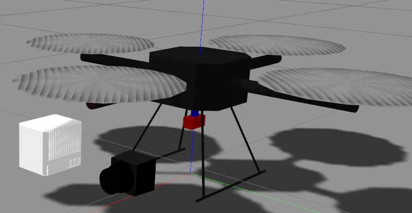
<joint name="camera_J2" type="fixed"> <parent link="link_2"/> <child link="camera_mount"/> <origin xyz="0.1 ${SizeGain*0.01+0.29} 0" rpy="${M_PI} 0 ${M_PI/2}" /> <axis xyz="1 0 0" /> <limit lower="-2.094" upper="2.670" effort="10" velocity="1.0" /> <joint_properties damping="0.0" friction="0.0"/> </joint>
<joint name="lidar_joint" type="fixed"> <parent link="link_2"/> <child link="livox_lidar_link"/> <origin xyz="-0.1 ${SizeGain*0.01+0.29} 0.002" rpy="${180*M_PI/180} ${0*M_PI/180} ${M_PI*0.5}" /> <axis xyz="1 0 0" /> </joint>
相机与激光雷达视野匹配
我们知道激光雷达是没有镜头的,所以激光雷达的视场角是多少就是多少,无法改变.(实际场景中)
那么想让相机与激光雷达的视野匹配,只能选择相机的镜头,让水平视场角和垂直视场角两者更为接近.
激光雷达仿真对应的具体型号是livox avia ,该雷达的视野如下:
非重复式扫描 70.4° * 77.2°
在gazebo中也是这样设置的
<xacro:property name="horizontal_fov" value="70.4"/> <xacro:property name="vertical_fov" value="77.2"/>
所以在gazebo中设置相机的参数如下:(水平角是70.4,像素是4096*3000)
<gazebo reference="camera_mount"> <turnGravityOff>false</turnGravityOff> <sensor type="camera" name="camera_node"> <update_rate>5</update_rate> <camera name="head"> <horizontal_fov>"${70.4*M_PI/180}"</horizontal_fov> <image> <width>4096</width> <height>3000</height> <format>R8G8B8</format> </image> <clip> <near>0.02</near> <far>300</far> </clip> <noise> <type>gaussian</type> <mean>0.0</mean> <stddev>0.007</stddev> </noise> </camera> <plugin name="gazebo_camera" filename="libgazebo_ros_camera.so"> <alwaysOn>true</alwaysOn> <updateRate>10</updateRate> <cameraName>/camera</cameraName> <imageTopicName>image_raw</imageTopicName> <cameraInfoTopicName>camera_info</cameraInfoTopicName> <frameName>camera_link</frameName> <hackBaseline>0.07</hackBaseline> <distortionK1>0.0</distortionK1> <distortionK2>0.0</distortionK2> <distortionK3>0.0</distortionK3> <distortionT1>0.0</distortionT1> <distortionT2>0.0</distortionT2> </plugin> </sensor> </gazebo>
rviz中检查成像效果
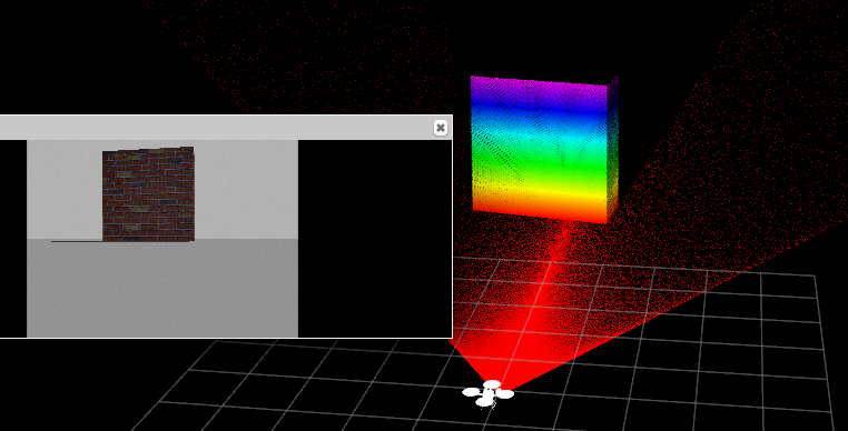
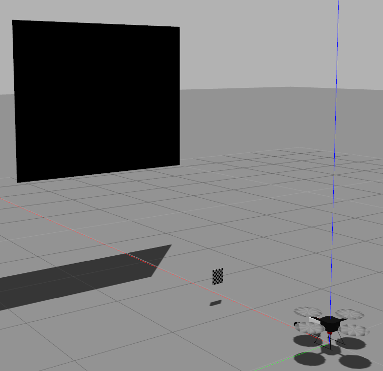
在云台前,放一个墙
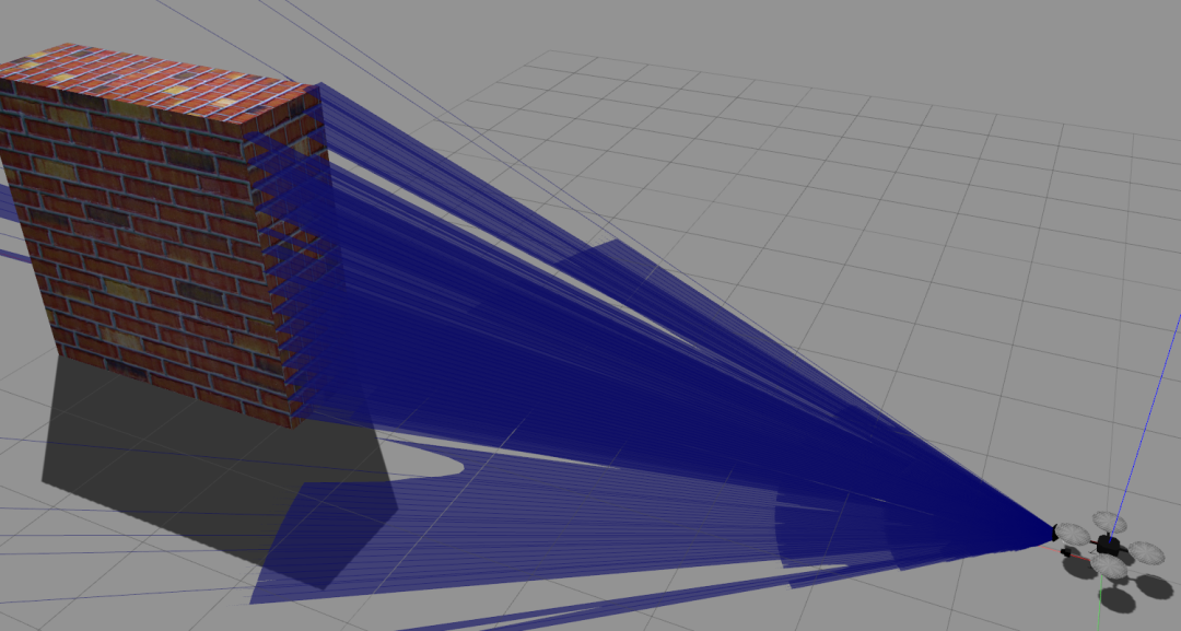
看激光雷达的点云和相机的图像的墙的占幅比,如果上面调的视野一致的化,那么应该不会差太多.
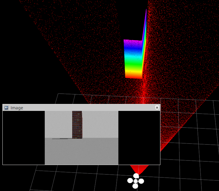
墙横过来的效果
创建标定棋盘
编辑一个棋盘的sdf文件,这种文件太长了,就不在这放了. 展示下想让棋盘待在空中不掉下来的关键部分:

static 为true 则不受重力影响
pose 就是 在world 的位置 x y z 和三个姿态角
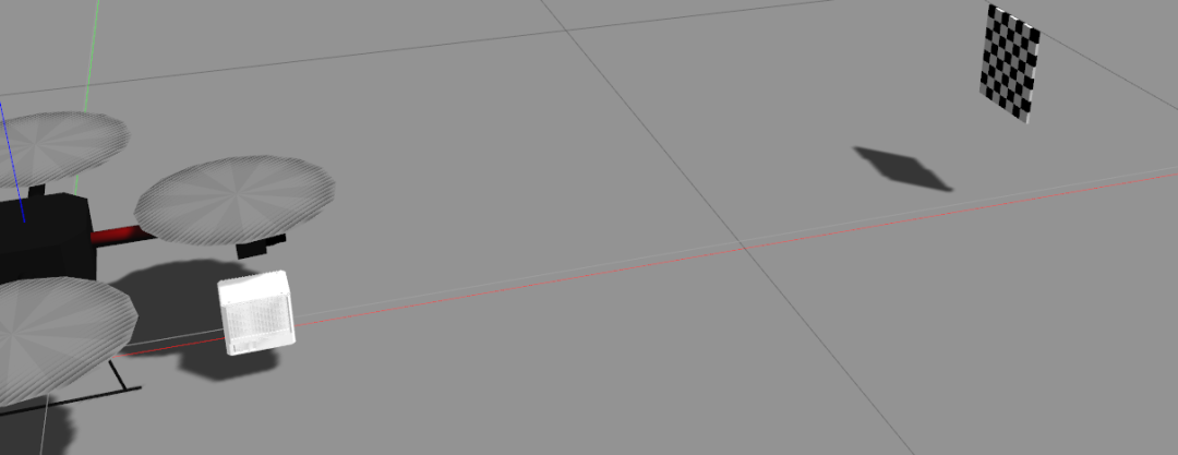
在rviz中检查下标定棋盘别太小就行.
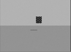
创建标定板
标定板最好可以设置大点的,矩形板就行
<?xml version='1.0'?><sdf version="1.4"><model name="board"> <pose>4 0 2 0 1.57079 0</pose> <static>true</static> <link name="board"> <pose>0.0 0.0 0.0 0.0 0.0 0.0</pose> <inertial> <mass>0.01</mass> <inertia> <!-- interias are tricky to compute --> <!-- http://answers.gazebosim.org/question/4372/the-inertia-matrix-explained/ --> <ixx>0.083</ixx> <!-- for a box: ixx = 0.083 * mass * (y*y + z*z) --> <ixy>0.0</ixy> <!-- for a box: ixy = 0 --> <ixz>0.0</ixz> <!-- for a box: ixz = 0 --> <iyy>0.083</iyy> <!-- for a box: iyy = 0.083 * mass * (x*x + z*z) --> <iyz>0.0</iyz> <!-- for a box: iyz = 0 --> <izz>0.083</izz> <!-- for a box: izz = 0.083 * mass * (x*x + y*y) --> </inertia> </inertial> <collision name="collision"> <geometry> <box> <size>0.02 0.02 0.005</size> </box> </geometry> </collision> <visual name="sqr11"> <geometry> <box> <size>2 2.5 0.005</size> </box> </geometry> <material> <ambient>0 0 0 1</ambient> <diffuse>0 0 0 1</diffuse> <specular>0.1 0.1 0.1 1</specular> <emissive>0 0 0 0</emissive> </material> </visual> </model></sdf>
场景效果检测
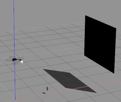
最后控制无人机飞起来,然后看标定板在相机和雷达里的视野情况
-
自动驾驶仿真软件汇总2023-06-06 488
-
自动驾驶仿真工具2023-06-01 549
-
EasyGo实时仿真丨控制器硬件在环(HIL)风电场景仿真测试应用2023-04-14 1079
-
在simulink中搭建逆变器仿真模型2023-02-28 1002
-
在gazebo中构建一个用于建图和导航的虚拟环境2021-12-17 1841
-
gazebo仿真常见问题遇见的坑记录2021-09-15 3035
-
在Mathematica计算软件中搭建机器人的仿真环境2021-09-07 1800
-
基于异步策略的Gazebo仿真优化方法2021-04-22 1079
-
ADAS整车在环虚拟仿真测试实验室中的搭建方案2020-07-09 2622
-
在仿真软件中进行电路搭建与完成瞬时现象的仿真实验2019-04-18 4584
-
如何利用TensorForce框架快速搭建深度强化学习模型2019-03-29 6105
-
利用gazebo搭建px4仿真系统2015-12-16 4528
全部0条评论

快来发表一下你的评论吧 !

