

制作一个带有PID控制器的线跟随机器人
机器人
描述
如果你想要制作一个遵循黑线行动的酷机器人。大概只需要在 2 小时内学习并制作就能够完成带有 PID 控制器的线跟随器机器人。
大多数漫游车自主机器人需要的一项功能是线路跟踪。该项目的目的是构建一个线跟随机器人,并以一种有趣的方式开始学习 PID 控制器。
构建
机器人与两个电机、Rosbot 底板和一个 5 通道传感器一起正常工作。与其他产品不同,您无需购买额外的 H 桥电机驱动器或各种组件,因为 Rosbot 基板具有内置的 2x H 桥双驱动器。只需将电机连接到 Rosbot 基板,它将提供比 Arduino Uno 更多的电力。
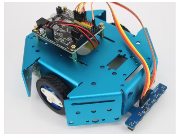
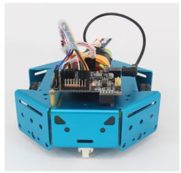
机器人框架: KittenBot 阳极氧化铝底盘
酷酷且坚固的底盘,带有大量安装孔(4.8 毫米乐高机械组),您绝对可以将此底盘重复用于其他有趣的项目。
机器人的大脑:RosBot 底板
一个基于 Arduino UNO 的主板,带有 2 个板载双 H 桥电机驱动器。
机器人的眼睛: 5 通道 IR 线跟随跟踪器传感器
5通道红外探测器,更准确、更稳定。
第 1 步:组装
这个机器人很容易组装,按照说明操作,大约需要 15 分钟。
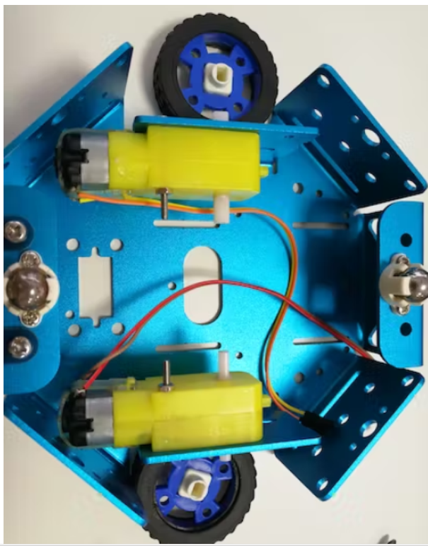
首先,将电机连接到底盘的侧面,只需插入橡胶轮即可。
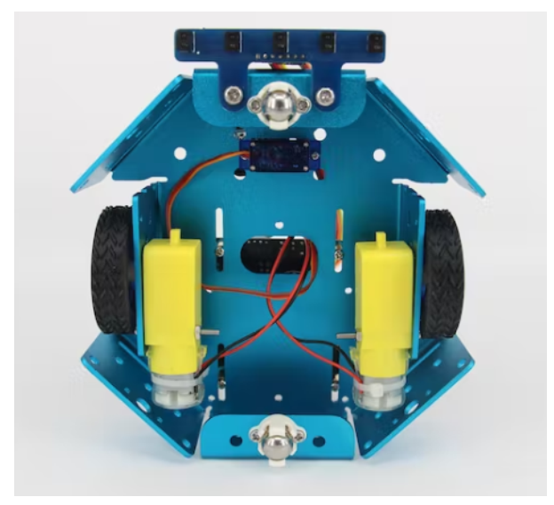
将 5 通道红外传感器安装到机箱前部。
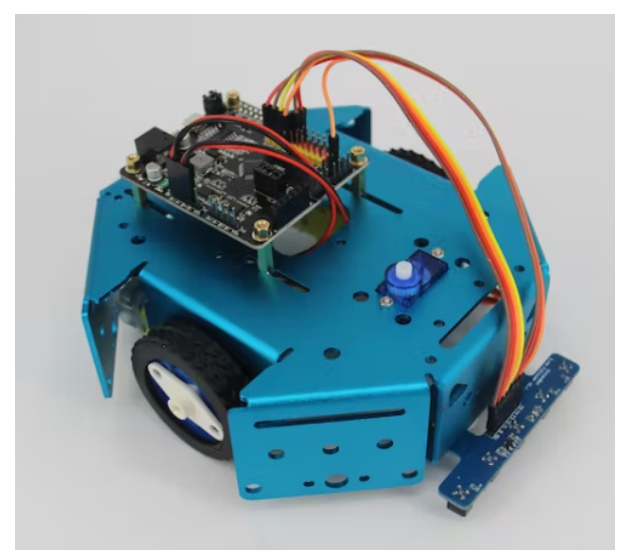
将您的 Rosbot 底板连接到底盘上,然后机器人就可以开始接线了。
第2步:连接
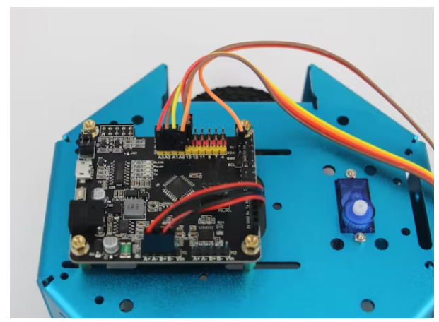
以下是 5 通道红外传感器的连接:
VCC 至 5V
GND 到 RosBot 的 GND
T1-T4 到引脚 A0-A3
T5 到 SDA 引脚
直流电机只需连接到引脚 A+A- 和引脚 B+B-。
编码
在代码中,我们有一个状态机来指示每个可能的传感器阵列输出。机器人根据传感器阵列输出向某个方向移动。
void stateMachine(int a) {
switch (a) {
case B00000:
outlineCnt++;
break;
case B11111:
outlineCnt++;
break;
case B00010:
case B00110:
outlineCnt = 0;
pixels.setPixelColor(2, pixels.Color(0, 50, 0));
bias = 1;
break;
case B00001:
case B00011:
outlineCnt = 0;
pixels.setPixelColor(2, pixels.Color(0, 200, 0));
bias = 2;
break;
case B00100:
outlineCnt = 0;
pixels.setPixelColor(2, pixels.Color(0, 0, 20));
bias = 0;
break;
case B01000:
case B01100:
outlineCnt = 0;
pixels.setPixelColor(2, pixels.Color(50, 0, 0));
bias = -1;
break;
case B10000:
case B11000:
outlineCnt = 0;
pixels.setPixelColor(2, pixels.Color(200, 0, 0));
bias = -2;
break;
default:
Serial.println(a,BIN);
outlineCnt++;
break;
}
到此我们已经设置了误差、比例项、积分项和导数项的值。
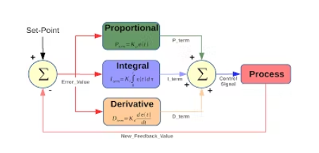
float Kp = 25;
float Ki = 0.15;
float Kd = 1200;
float error, errorLast, erroInte;
float calcPid(float input) {
float errorDiff;
float output;
error = error * 0.7 + input * 0.3; // filter
//error = input;
errorDiff = error - errorLast;
erroInte = constrain(erroInte + error, -50, 50);
output = Kp * error + Ki * erroInte + Kd * errorDiff;
Serial.print(error); Serial.print(' ');
Serial.print(erroInte); Serial.print(' ');
Serial.print(errorDiff); Serial.print(' ');
Serial.println(output);
errorLast = error;
return output;
-
教你做个PID控制巡线机器人2023-09-25 533
-
基于Arduino Nano的PID线路跟随机器人2022-12-23 1045
-
基于PID的线跟随机器人2022-12-16 530
-
如何使用PIC微控制器构建一个线路跟随机器人2022-11-30 2188
-
使用Pico的线跟随机器人2022-11-15 862
-
PID控制线跟随机器人2022-11-14 720
-
最简单的线跟随机器人2022-11-08 481
-
如何使用Arduino制作跟随机器人2022-10-31 932
-
如何使用AVR单片机构建一个线跟随机器人2022-09-08 1524
-
在不使用微控制器的情况下构建一个线跟随机器人2022-07-25 1539
-
可通过蓝牙控制的单PCB小线跟随机器人2022-07-08 2451
-
线跟随机器人如何导航?2022-06-22 930
-
基于ATmega16构建的线跟随机器人的完整电路图2022-06-08 3036
全部0条评论

快来发表一下你的评论吧 !

