

利用ATtiny85实现植物浇水自主系统的设计
描述
你是否有想实现的下列之一的功能:
收到警告(警报声、短信等)并去给植物浇水?
一段时间后(通常是几天),计时机器会倒一些水。也许你的工厂当时不这样做!
完全依赖湿度传感器。大错!局部湿度可能会误导锅的平均湿度!
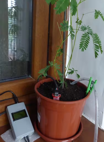
您的设备正在监控植物,在需要时浇水。您只需不时访问它,并在需要时重新填充水容器。
这个项目中选择了最后一个选项。
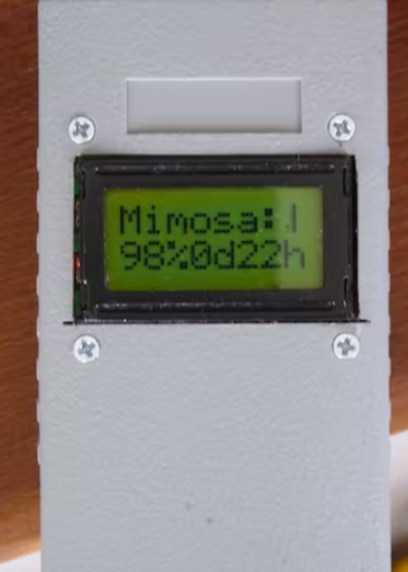
这是显示含羞草表情符号的中央单元:快乐 :) 正常 :| 或不满意 :( ,然后是土壤湿度 (%)、自上次抽水以来的天数和小时数。当然,您可以使用任何其他显示器。这个显示器是从另一块板上重复使用的 (Pololu A-Star Prime)。
湿度传感器
它是一种基于电阻率的传感器,不会被腐蚀。如果您每次只打开几毫秒的电源,刚好足以读取湿度,它就可以正常工作。正好我展示的这个,也工作了多年,没有任何腐蚀迹象。只需使用附带的软件。
但是可能会出现其他问题:湿泥附着在传感器上,因此表明局部湿度与其余部分不同!同时如果传感器离水管太远,读数会有很大的延迟:需要水在锅中扩散所需的时间。把它放在离水管较近的地方停止抽水,以免水分太多。根据您的工厂要求更改软件中的湿度阈值。这个抽水低于 95% 的湿度(在用我的含羞草做了一些测试后,我将此阈值更改为 75%),持续一定的秒数,具体取决于底池大小。然后,在读取时间(10-15 分钟)之后,如果指示的湿度没有超过阈值,则泵送新的水量,但迭代次数有限。
这种方法可以让水有时间在锅中扩散。在给定的时间间隔(8-12 小时)内只允许浇水两次,以避免在扩散之前洒水,避免一些可能的传感器临时错误。建议每隔几个月重新校准湿度传感器:在软件中调整阈值:传感器在空气中的值(0% 湿度)和传感器短路的值(100% 湿度)。
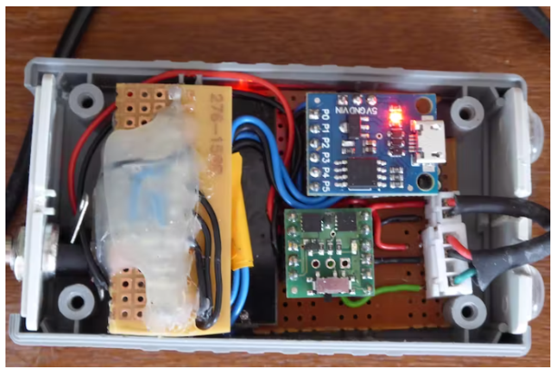
作为微控制器,我们建议使用 AtTiny85:它有必要的 IO 引脚,刚好够用,并且相比其他微控制器便宜。
整个设备(包括泵)由 220V 电源适配器持续供电,提供 9V/0.5A。如果发生电源故障(希望持续不到几天,否则植物会变干!),这不是问题。如果需要,系统将重新启动,读取湿度和抽水,然后将重置小时和天数计数器。
为泵供电由 Mosfet 模块完成,但也可以通过其他方式(例如继电器)完成。显示器可以是任何其他带有 I2C 接口的显示器。这个有一个并行接口,所以需要一个I2C适配器。
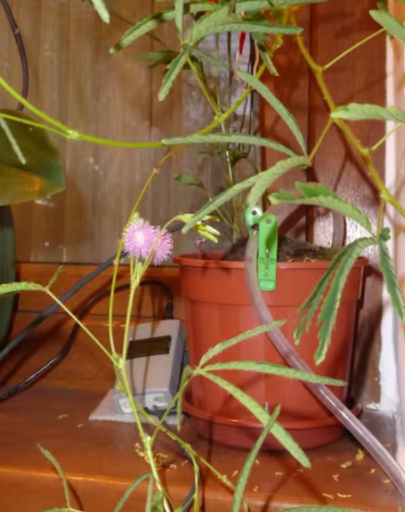
使用一年后
该项目的运行时间超过 18 个月。不过有一次,突然遇到湿度传感器停止工作的情况。幸运的是,在此期间并没有什么和湿度有关的环境需求,该软件每 2 天抽一次水。现在它已被替换并且一切正常。
注:必须在代码中测试和设置新的湿度阈值,从 95% 到 75%!产品和土壤盐度的可变性!
Arduino code for Attiny-plant-care:
/* Sketch for ATtiny85. Based on the Digispark (Use Digispark Default 16.5 MHz), no port select.
* Compile, Upload and then coonect ATtiny85 to USB.
* {ATtiny85 alone pins: 1=PB5, 2=PB3,ADC3, 3=PB4,ADC2, 4=GND, 5=PB0,MOSI,SDA, 6=PB1,MISO, 7=PB2,SCK,SCL, 8=VCC}
* ATtiny Pin 5 = PB0 (P0 on ATTiny board) = SDA
* ATtiny Pin 7 = PB2 (P2 on ATTiny board) = SCK=SCL
* ATtiny PB1 = to SWITCH power of a POLOLU MOSFET: power the Pump (6-12V)
* ATtiny PB3 = Humidity sensor output= analog read
* ATtiny PB4 = Power for the sensor (pin: 20mA = sufficient)
* Uses 26 mA for CPU, Sensor + Mosfet on + Display
* Uses 20 mA for CPU + Display (between readings)
* Uses 8 mA in deep sleep (Display on only)
* Between reads: deep sleep. Protection against over-watering by humidity sensor.
*/
#define LED_BUILTIN PB5 // Change PB5 to PB1 only for testing delays
//This runs each time the watch dog wakes us up from sleep
void setup() {
void loop() {
// The pump is started if humidity drops below a level determined for each plant!
// Show the results on the screen
// ===================================================================
#include
#include
#define GPIO_ADDR 0x27 // the address i2c for this 8x2 LCD
LiquidCrystal_I2C lcd(GPIO_ADDR, 8, 2); // set the I2C address & 8/16 chars / 2 lines
// Utility sleep macros
#include
#include
#define adc_disable() (ADCSRA &= ~(1<
#define powsen PB4 // PB4 provides 4.1V to power the humidity sensor
#define sensor PB3 // Sensor data pin for analog read
#define pump PB1 // Pin for LED & MOSFET feeding the Pump
// Reading humidity once in 30min...1hour is sufficient:
int D, H, nr=100; // Attiny85 will sleep nr*9 (sec.) (E.g. 200=>30min; 400=>1h))
unsigned long psec, corr=nr*300; // time counter since start or watering
ISR(WDT_vect) {
//Don't do anything. This is just here for wake up.
}
lcd.init(); lcd.backlight(); lcd.clear();
pinMode(powsen,OUTPUT); // Power to the sensor by powsen PIN
pinMode(sensor, INPUT); // Sensor read value from sensor PIN
pinMode(pump, OUTPUT); // Pump control PIN
pinMode(LED_BUILTIN, OUTPUT);
set_sleep_mode(SLEEP_MODE_PWR_DOWN); // sleep mode is set here
sleep_enable(); // enables the sleep bit in the mcucr register, so sleep is possible
psec=0; // Starting moment
}
adc_enable();
digitalWrite(LED_BUILTIN, HIGH); // turn the LED on (HIGH is the voltage level)
digitalWrite(powsen,HIGH); // Power on the sensor
int humidity=analogRead(sensor); // Read sensor data
delay(200); // A short time, just to read the sensor!
digitalWrite(powsen,LOW); // Power off the humidity sensor
digitalWrite(LED_BUILTIN, LOW); // turn the LED off by making the voltage LOW
// Convert analog values from sensor to humidity. Tested: free and short-circuit.
humidity = constrain(humidity, 85, 660); // accept values between these limits for 4.8V on sensor
humidity = map(humidity, 85, 660, 0, 100); // and map them between 0 and 100%
// Then, the pump cannot restart before 'pause', waiting for water to diffuse in the pot.
// Set below the DRY Limit for Your Plant (E.G.: 95):
if (humidity<=95) {
digitalWrite(pump,HIGH); // Power the pump through a Pololu-LV-MOSFET
delay(15000); // Time [ms] to pump the tested REQUIRED volume of WATER to the plant!!
digitalWrite(pump,LOW); // Power down the pump through the MOSFET
delay(1000);
psec=0; // Reset timer of water pumping.
// Test that after [nr*9] seconds (15min in this case), water was absorbed and sensor is above threshold.
// Otherwise, the pump will start again after. Warning: too much water can be bad for your plant!
}
lcd.setCursor(0, 0); lcd.print("Mimosa:");
if (humidity>95)
if (humidity>97)
lcd.print(")");
else
lcd.print("|");
else
lcd.print("(");
lcd.setCursor(0, 1);
lcd.print(humidity); lcd.print("%"); // Write on LCD the humidity (%) and
D=psec/86400; // days since last watering/reset ...
H=(psec%86400)/3600; // and hours
lcd.print(D); lcd.print("d");
lcd.print(H); lcd.print("h ");
// Most of the time, go to sleep for 'nr' multiples of 8 seconds + opp. time
adc_disable(); // ADC uses ~320uA
for (int i=0; i
sleep_mode(); //Go to sleep! Wake up n sec later and work
}
delay(corr); // Timer correction since sleep is less than nr*9 sec.
psec+=nr*9; // Update timer after deep sleep for Half an hour
}
void setup_watchdog(int timerPrescaler) {
//Sets the watchdog timer to wake up, but not reset
//0=16ms, 1=32ms, 2=64ms, 3=128ms, 4=250ms, 5=500ms
//6=1sec, 7=2sec, 8=4sec, 9=8sec
//From: http://interface.khm.de/index.php/lab/experiments/sleep_watchdog_battery/
if (timerPrescaler > 9 ) timerPrescaler = 9; //Limit incoming amount to legal settings
byte bb = timerPrescaler & 7;
if (timerPrescaler > 7) bb |= (1<<5); //Set the special 5th bit if necessary
//This order of commands is important and cannot be combined
MCUSR &= ~(1<
WDTCR |= _BV(WDIE); //Set the interrupt enable, will keep unit from resetting after each int
}
-
使用ATTINY85的简单RGB桌面时钟2023-06-09 1025
-
将ATtiny85与Arduino IDE结合使用2023-02-10 2449
-
基于Attiny85的macropad2023-01-30 735
-
带蓝牙的Attiny85/842022-12-20 992
-
编程ATTINY85芯片开源分享2022-11-28 1433
-
DIY ATtiny85 Roomba墙2022-11-24 647
-
带有ATTINY85的迷你Arduino2022-10-31 1728
-
ATtiny85电子负载开源设计2022-08-10 1624
-
如何使用Arduino Uno对ATtiny85进行编程2022-08-05 11492
-
ATtiny85突破开源项目2022-07-25 717
-
带ATTINY85的交通灯2022-07-18 682
-
如何用Attiny85控制水泵浇花2022-02-22 861
-
用Attiny85控制水泵浇花2021-12-27 906
-
Digispark ATtiny85 ADC采样 analogRead()2021-11-30 996
全部0条评论

快来发表一下你的评论吧 !
