

基于Linux的mpu6050驱动的实现
描述
I2C Linux驱动篇
本篇讲解mpu6050基于Linux的驱动的实现。
Linux I2C架构
Linux内核已经为我们编写好了I2C的架构,从设备信息可以在内核文件中直接写死,也可以通过设备树来提供,我们只需要实现i2c_driver,然后注册到i2c架构中即可。
i2c的内核架构源码位于:
driversi2c
I2C核心(i2c_core)
I2C核心维护了i2c_bus结构体,提供了I2C总线驱动和设备驱动的注册、注销方法,维护了I2C总线的驱动、设备链表,实现了设备、驱动的匹配探测。此部分代码由Linux内核提供。
I2C总线驱动
I2C总线驱动维护了I2C适配器数据结构(i2c_adapter)和适配器的通信方法数据结构(i2c_algorithm)。所以I2C总线驱动可控制I2C适配器产生start、stop、ACK等。此部分代码由具体的芯片厂商提供,比如Samsung、高通。
I2C设备驱动
I2C设备驱动主要维护两个结构体:i2c_driver和i2c_client,实现和用户交互的文件操作集合fops、cdev等。此部分代码就是驱动开发者需要完成的。
Linux内核中描述I2C的四个核心结构体
1)i2c_client—挂在I2C总线上的I2C从设备
每一个i2c从设备都需要用一个i2c_client结构体来描述,i2c_client对应真实的i2c物理设备device。

但是i2c_client不是我们自己写程序去创建的,而是通过以下常用的方式自动创建的:
方法一: 分配、设置、注册i2c_board_info
方法二: 获取adapter调用i2c_new_device
方法三: 通过设备树(devicetree)创建
方法1和方法2通过platform创建,这两种方法在内核3.0版本以前使用所以在这不详细介绍;方法3是最新的方法,3.0版本之后的内核都是通过这种方式创建的,文章后面的案例就按方法3。
2)i2c_adapter
I2C总线适配器,即soc中的I2C总线控制器,硬件上每一对I2C总线都对应一个适配器来控制它。在Linux内核代码中,每一个adapter提供了一个描述它的结构(struct i2c_adapter),再通过i2c core层将i2c设备与i2c adapter关联起来。主要用来完成i2c总线控制器相关的数据通信,此结构体在芯片厂商提供的代码中维护。

3)i2c_algorithm
I2C总线数据通信算法,通过管理I2C总线控制器,实现对I2C总线上数据的发送和接收等操作。亦可以理解为I2C总线控制器(适配器adapter)对应的驱动程序,每一个适配器对应一个驱动程序,用来描述适配器和设备之间的通信方法,由芯片厂商去实现的。

4)i2c_driver
用于管理I2C的驱动程序和i2c设备(client)的匹配探测,实现与应用层交互的文件操作集合fops、cdev等。

设备树
1. 硬件电路图如下:


由上图所示硬件使用的是I2C通道5,

2. 查找exnos4412的datasheet 29.6.1节,对应的基地址为0x138B0000。

3. 由上图可知中断引脚复用的是GPX3_3。
4. 在上一篇中,我们已经得到mpu6050从设备地址为0x68。
linux内核中三星已经为I2C控制器和设备节点的编写提供了说明手册:
G:linux-3.14-fs4412Documentationdevicetreebindingsi2ci2c-s3c2410.txt
该文档提供了一个具体范例,如下:
Example:
i2c@13870000 {
compatible = "samsung,s3c2440-i2c";
reg = <0x13870000 0x100>;
interrupts = <345>;
samsung,i2c-sda-delay = <100>;
samsung,i2c-max-bus-freq = <100000>;
/* Samsung GPIO variant begins here */
gpios = <&gpd1 2 0 /* SDA */
&gpd1 3 0 /* SCL */>;
/* Samsung GPIO variant ends here */
/* Pinctrl variant begins here */
pinctrl-0 = <&i2c3_bus>;
pinctrl-names = "default";
/* Pinctrl variant ends here */
wm8994@1a {
compatible = "wlf,wm8994";
reg = <0x1a>;
};
};
注意:三星的exynos4412的i2c控制器驱动仍然沿用了s3c2410的驱动。
综上,最终I2C设备树节点编写如下:
   i2c@138B0000 {          基地址是 138B0000
       samsung,i2c-sda-delay = <100>;
       samsung,i2c-max-bus-freq = <20000>;
       pinctrl-0 =<&i2c5_bus>;            通道5
       pinctrl-names = "default";
       status = "okay";
       mpu6050-3-asix@68 {
           compatible = "invensense,mpu6050";
           reg= <0x68>;           从设备地址
           interrupt-parent = <&gpx3>;   中断父节点
           interrupts= <3  2>;    中断index=3,中断触发方式:下降沿触发
       };
     };
其中 外面节点 i2c@138B0000{}是i2c控制器设备树信息,子节点
mpu6050-3-asix@68{}是从设备mpu6050的设备树节点信息。
【注意】关于设备树的编译烧录,本篇不做详细说明,后续会开一篇详细讲述设备树的使用。
结构体之间关系如下:
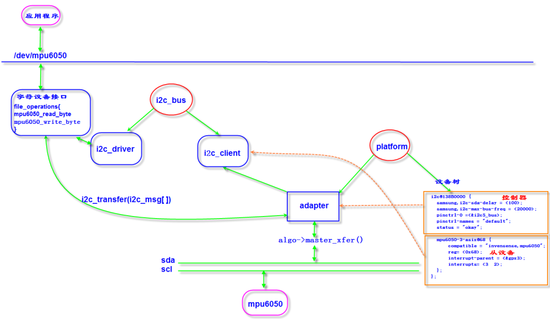
1. 设备树节点分为控制器和从设备两部分,控制器节点信息会通过platform总线与控制器驱动匹配,控制器驱动已经由内核提供,结构体如下:
static struct platform_driver s3c24xx_i2c_driver = {
.probe = s3c24xx_i2c_probe,
.remove = s3c24xx_i2c_remove,
.id_table = s3c24xx_driver_ids,
.driver = {
.owner = THIS_MODULE,
.name = "s3c-i2c",
.pm = S3C24XX_DEV_PM_OPS,
.of_match_table = of_match_ptr(s3c24xx_i2c_match),
},
};
static const struct of_device_id s3c24xx_i2c_match[] = {
{ .compatible = "samsung,s3c2410-i2c", .data = (void *)0 },
{ .compatible = "samsung,s3c2440-i2c", .data = (void *)QUIRK_S3C2440 },
{ .compatible = "samsung,s3c2440-hdmiphy-i2c",
.data = (void *)(QUIRK_S3C2440 | QUIRK_HDMIPHY | QUIRK_NO_GPIO) },
{ .compatible = "samsung,exynos5440-i2c",
.data = (void *)(QUIRK_S3C2440 | QUIRK_NO_GPIO) },
{ .compatible = "samsung,exynos5-sata-phy-i2c",
.data = (void *)(QUIRK_S3C2440 | QUIRK_POLL | QUIRK_NO_GPIO) },
{},
};
MODULE_DEVICE_TABLE(of, s3c24xx_i2c_match);
2. 从设备节点信息最终会通过i2c_bus与i2c_driver匹配,i2c_driver需要由开发者自己注册,并实现字符设备接口和创建设备节点/dev/mpu6050;
3. 用户通过字符设备节点/dev/mpu6050调用内核的注册的接口函数mpu6050_read_byte、mpu6050_write_byte;4. 内核的i2c core模块提供了i2c协议相关的核心函数,在实现读写操作的时候,需要通过一个重要的函数i2c_transfer(),这个函数是i2c核心提供给设备驱动的,通过它发送的数据需要被打包成i2c_msg结构,这个函数最终会回调相应i2c_adapter->i2c_algorithm->master_xfer()接口将i2c_msg对象发送到i2c物理控制器。
【注】实例所用soc是exynos4412,为三星公司所出品,所以i2c控制器设备树节点信息可以参考linux内核根目录以下件:
Documentationdevicetreebindingsi2ci2c-s3c2410.txt。
不同的公司设计的i2c控制器设备树节点信息填写格式不尽相同,需要根据具体产品填写。
编写驱动代码
分配、设置、注册i2c_driver结构体
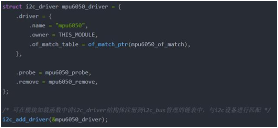
i2c总线驱动模型属于设备模型中的一类,同样struct i2c_driver结构体继承于struct driver,匹配方法和设备模型中讲的一样,这里要去匹配设备树,所以必须实现i2c_driver结构体中的driver成员中的of_match_table成员:

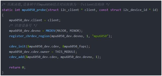
如果和设备树匹配成功,那么就会调用probe函数
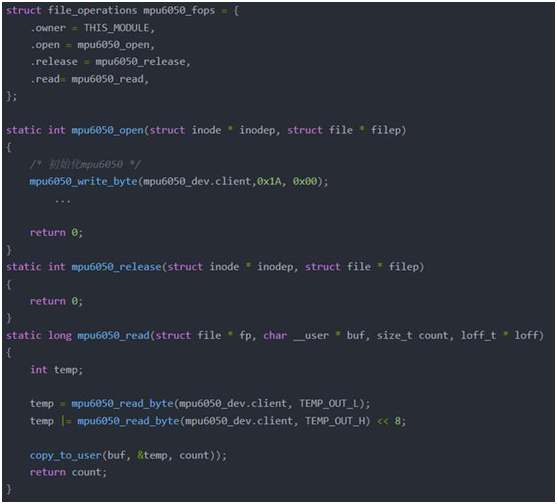
实现文件操作集合
如何填充i2c_msg?
根据mpu6050的datasheet可知,向mpu6050写入1个data和读取1个值的时序分别如下图所示。


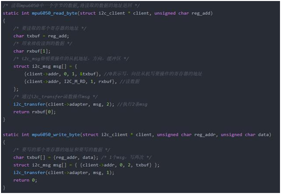
基于Linux的i2c架构编写驱动程序,我们需要用struct i2c_msg结构体来表示上述所有信息。

编写i2c_msg信息原则如下:
-
有几个S信号,msg数组就要有几个元素;
-
addr为从设备地址,通过i2c总线调用注册的probe函数的参数i2c_client传递下来;
-
len的长度不包括S、AD、ACK、P;
-
buf为要发送或者要读取的DATA的内存地址。
综上所述:
-
Single-Byte Write Sequence时序只需要1个i2c_msg,len值为2,buf内容为是RA、DATA;
-
Single-Byte Read Sequence时序需要2个i2c_msg,len值分别都为1,第1个msg的buf是RA,第2个msg的buf缓冲区用于存取从设备发送的DATA。
I2C内核架构分析
本章以linux3.14.0为参考, 讨论Linux中的i2c控制器驱动是如何实现的。
驱动入口
三星的i2c控制器驱动是基于platform总线实现的,struct platform_driver定义如下:


当设备树节点信息的compatible信息和注册的platform_driver.driver. of_match_table字符串会通过platform总线的macth方法进行配对,匹配成功后会调用probe函数s3c24xx_i2c_probe()。
驱动核心结构
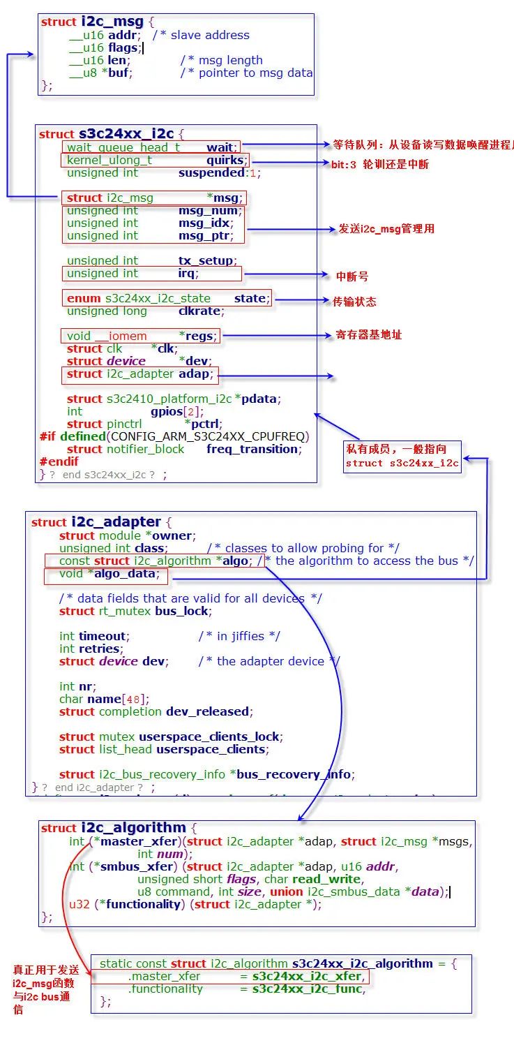
要理解i2c的内核架构首先必须了解一下这几个机构体:
s3c24xx_i2c
该结构体是三星i2c控制器专用结构体,描述了控制器的所有资源,包括用于等待中断唤醒的等待队列、传输i2c_msg的临时指针、记录与硬件通信的状态、中断号、控制器基地址、时钟、i2c_adapter、设备树信息pdata等。i2c控制器初始化的时候会为该控制器创建该结构体变量,并初始化之。
i2c_adapter
对象实现了一组通过一个i2c控制器发送消息的所有信息, 包括时序, 地址等等, 即封装了i2c控制器的"控制信息"。它被i2c主机驱动创建, 通过clien域和i2c_client和i2c_driver相连, 这样设备端驱动就可以通过其中的方法以及i2c物理控制器来和一个i2c总线的物理设备进行交互。
i2c_algorithm
描述一个i2c主机的发送时序的信息,该类的对象algo是i2c_adapter的一个域,其中注册的函数master_xfer()最终被设备驱动端的i2c_transfer()回调。
i2c_msg
描述一个在设备端和主机端之间进行流动的数据, 在设备驱动中打包并通过i2c_transfer()发送。相当于skbuf之于网络设备,urb之于USB设备。
这几个结构体之间关系:
i2c_client
描述一个挂接在硬件i2c总线上的设备的设备信息,即i2c设备的设备对象,与i2c_driver对象匹配成功后通过detected和i2c_driver以及i2c_adapter相连,在控制器驱动与控制器设备匹配成功后被控制器驱动通过i2c_new_device()创建。从设备所挂载的i2c控制器会在初始化的时候保存到成员adapter。
i2c_driver
描述一个挂接在硬件i2c总线上的设备的驱动方法,即i2c设备的驱动对象,通过i2c_bus_type和设备信息i2c_client匹配,匹配成功后通过clients和i2c_client对象以及i2c_adapter对象相连。
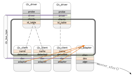
如上图所示:Linux内核维护了i2c bus总线,所有的i2c从设备信息都会转换成i2c_client,并注册到i2c总线,没有设备的情况下一般填写在一下文件中:
linux-3.14-fs4412archarmmach-s5pc100 Mach-smdkc100.c

内核启动会将i2c_board_info结构体转换成i2c_client。
有设备树的情况下,内核启动会自动将设备树节点转换成i2c_client。
i2c_adapter
我首先说i2c_adapter, 并不是编写一个i2c设备驱动需要它, 通常我们在配置内核的时候已经将i2c控制器的设备信息和驱动已经编译进内核了, 就是这个adapter对象已经创建好了, 但是了解其中的成员对于理解i2c驱动框架非常重要, 所有的设备驱动都要经过这个对象的处理才能和物理设备通信
//include/linux/i2c.h
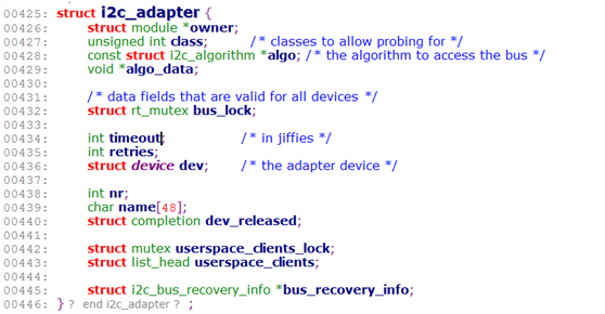
428-->这个i2c控制器需要的控制算法, 其中最重要的成员是master_xfer()接口, 这个接口是硬件相关的, 里面的操作都是基于具体的SoC i2c寄存器的, 它将完成将数据发送到物理i2c控制器的"最后一公里"
436-->表示这个一个device, 会挂接到内核中的链表中来管理, 其中的
443-->这个节点将一个i2c_adapter对象和它所属的i2c_client对象以及相应的i2c_driver对象连接到一起
下面是2个i2c-core.c提供的i2c_adapter直接相关的操作API, 通常也不需要设备驱动开发中使用。
Adapter初始化
i2c控制器设备树节点信息通过platform总线传递下来,即参数pdev。probe函数主要功能是初始化adapter,申请i2c控制器需要的各种资源,同时通过设备树节点初始化该控制器下的所有从设备,创建i2c_client结构体。
ps3c24xx_i2c_probe
|
static int s3c24xx_i2c_probe(struct platform_device *pdev) { struct s3c24xx_i2c *i2c;//最重要的结构体 //保存设备树信息 struct s3c2410_platform_i2c *pdata = NULL; struct resource *res; int ret;
if (!pdev->dev.of_node) { pdata = dev_get_platdata(&pdev->dev); if (!pdata) { dev_err(&pdev->dev, "no platform data "); return -EINVAL; } } /*为结构体变量i2c分配内存*/ i2c = devm_kzalloc(&pdev->dev, sizeof(struct s3c24xx_i2c), GFP_KERNEL); if (!i2c) { dev_err(&pdev->dev, "no memory for state "); return -ENOMEM; }
i2c->pdata = devm_kzalloc(&pdev->dev, sizeof(*pdata), GFP_KERNEL); if (!i2c->pdata) { dev_err(&pdev->dev, "no memory for platform data "); return -ENOMEM; } /*i2c控制器的一些特殊行为 #define QUIRK_S3C2440 (1 << 0) #define QUIRK_HDMIPHY (1 << 1) #define QUIRK_NO_GPIO (1 << 2) #define QUIRK_POLL (1 << 3) 其中bite:3如果采用轮训方式与底层硬件通信值为1,中断方式值为0*/ i2c->quirks = s3c24xx_get_device_quirks(pdev); if (pdata) memcpy(i2c->pdata, pdata, sizeof(*pdata)); else s3c24xx_i2c_parse_dt(pdev->dev.of_node, i2c);
strlcpy(i2c->adap.name, "s3c2410-i2c", sizeof(i2c->adap.name)); i2c->adap.owner = THIS_MODULE; /*为i2c_msg传输方法赋值,*/ i2c->adap.algo = &s3c24xx_i2c_algorithm; i2c->adap.retries = 2; i2c->adap.class = I2C_CLASS_HWMON | I2C_CLASS_SPD; i2c->tx_setup = 50; //初始化等待队列,该等待队列用于唤醒读写数据的进程 init_waitqueue_head(&i2c->wait);
/* find the clock and enable it */
i2c->dev = &pdev->dev; //获取时钟 i2c->clk = devm_clk_get(&pdev->dev, "i2c"); if (IS_ERR(i2c->clk)) { dev_err(&pdev->dev, "cannot get clock "); return -ENOENT; } dev_dbg(&pdev->dev, "clock source %p ", i2c->clk); /* map the registers */ //通过pdev得到i2c控制器的寄存器地址资源 res = platform_get_resource(pdev, IORESOURCE_MEM, 0); //映射i2c控制器的物理基地址为虚拟基地址 i2c->regs = devm_ioremap_resource(&pdev->dev, res);
if (IS_ERR(i2c->regs)) return PTR_ERR(i2c->regs);
dev_dbg(&pdev->dev, "registers %p (%p) ", i2c->regs, res);
/* setup info block for the i2c core */ /*将结构体变量i2c保存到i2c_adapter的私有变量指针algo_data, 编写i2c设备驱动可以通过adapter指针找到结构体i2c*/ i2c->adap.algo_data = i2c; i2c->adap.dev.parent = &pdev->dev;
i2c->pctrl = devm_pinctrl_get_select_default(i2c->dev);
/* inititalise the i2c gpio lines */ //得到i2c复用的gpio引脚并初始化 if (i2c->pdata->cfg_gpio) { i2c->pdata->cfg_gpio(to_platform_device(i2c->dev)); } else if (IS_ERR(i2c->pctrl) && s3c24xx_i2c_parse_dt_gpio(i2c)) { return -EINVAL; }
/* initialise the i2c controller */
clk_prepare_enable(i2c->clk); /*将从设备地址写入寄存器S3C2410_IICADD,同时初始化时钟频率*/ ret = s3c24xx_i2c_init(i2c); clk_disable_unprepare(i2c->clk); if (ret != 0) { dev_err(&pdev->dev, "I2C controller init failed "); return ret; } /* find the IRQ for this unit (note, this relies on the init call to * ensure no current IRQs pending */
if (!(i2c->quirks & QUIRK_POLL)) { /*从plat_device中获得中断号*/ i2c->irq = ret = platform_get_irq(pdev, 0); if (ret <= 0) { dev_err(&pdev->dev, "cannot find IRQ "); return ret; } /*注册中断处理函数s3c24xx_i2c_irq()*/ ret = devm_request_irq(&pdev->dev, i2c->irq, s3c24xx_i2c_irq, 0, dev_name(&pdev->dev), i2c);
if (ret != 0) { dev_err(&pdev->dev, "cannot claim IRQ %d ", i2c->irq); return ret; } }
ret = s3c24xx_i2c_register_cpufreq(i2c); if (ret < 0) { dev_err(&pdev->dev, "failed to register cpufreq notifier "); return ret; }
/* Note, previous versions of the driver used i2c_add_adapter() * to add the bus at any number. We now pass the bus number via * the platform data, so if unset it will now default to always * being bus 0. */ /*保存i2c控制器的通道号,本例是bus 5*/ i2c->adap.nr = i2c->pdata->bus_num; i2c->adap.dev.of_node = pdev->dev.of_node; //注册adapter ret = i2c_add_numbered_adapter(&i2c->adap); if (ret < 0) { dev_err(&pdev->dev, "failed to add bus to i2c core "); s3c24xx_i2c_deregister_cpufreq(i2c); return ret; } /*保存私有变量i2c到pdev->dev->p->driver_data*/ platform_set_drvdata(pdev, i2c);
pm_runtime_enable(&pdev->dev); pm_runtime_enable(&i2c->adap.dev);
dev_info(&pdev->dev, "%s: S3C I2C adapter ", dev_name(&i2c->adap.dev)); return 0; } |
i2c_add_numbered_adapter
老版本的注册函数为i2c_add_adapter()新的版本对该函数做了封装,将i2c控制的通道号做了注册,默认情况下nr值为0.
i2c_add_numbered_adapter->__i2c_add_numbered_adapter-> i2c_register_adapter
int   i2c_add_numbered_adapter(struct i2c_adapter *adap)
{
       if (adap->nr == -1) /* -1 means   dynamically assign bus id */
              return i2c_add_adapter(adap);
       return __i2c_add_numbered_adapter(adap);
}
i2c_add_adapter
|
static int i2c_register_adapter(struct i2c_adapter *adap) { int res = 0;
/* Can't register until after driver model init */ if (unlikely(WARN_ON(!i2c_bus_type.p))) { res = -EAGAIN; goto out_list; }
/* Sanity checks */ if (unlikely(adap->name[0] == '�')) { pr_err("i2c-core: Attempt to register an adapter with " "no name! "); return -EINVAL; } if (unlikely(!adap->algo)) { pr_err("i2c-core: Attempt to register adapter '%s' with " "no algo! ", adap->name); return -EINVAL; }
rt_mutex_init(&adap->bus_lock); mutex_init(&adap->userspace_clients_lock); INIT_LIST_HEAD(&adap->userspace_clients);
/* Set default timeout to 1 second if not already set */ if (adap->timeout == 0) adap->timeout = HZ; //设置adapter名字,本例注册后会生成以下节点/dev/i2c-5 dev_set_name(&adap->dev, "i2c-%d", adap->nr); adap->dev.bus = &i2c_bus_type; adap->dev.type = &i2c_adapter_type; res = device_register(&adap->dev); if (res) goto out_list; dev_dbg(&adap->dev, "adapter [%s] registered ", adap->name); #ifdef CONFIG_I2C_COMPAT res = class_compat_create_link(i2c_adapter_compat_class, &adap->dev, adap->dev.parent); if (res) dev_warn(&adap->dev, "Failed to create compatibility class link "); #endif /* bus recovery specific initialization */ /*初始化sda、scl,通常这两个引脚会复用gpio引脚*/ if (adap->bus_recovery_info) { struct i2c_bus_recovery_info *bri = adap->bus_recovery_info;
if (!bri->recover_bus) { dev_err(&adap->dev, "No recover_bus() found, not using recovery "); adap->bus_recovery_info = NULL; goto exit_recovery; }
/* Generic GPIO recovery */ if (bri->recover_bus == i2c_generic_gpio_recovery) { if (!gpio_is_valid(bri->scl_gpio)) { dev_err(&adap->dev, "Invalid SCL gpio, not using recovery "); adap->bus_recovery_info = NULL; goto exit_recovery; }
if (gpio_is_valid(bri->sda_gpio)) bri->get_sda = get_sda_gpio_value; else bri->get_sda = NULL; /*sda、scl资源赋值*/ bri->get_scl = get_scl_gpio_value; bri->set_scl = set_scl_gpio_value; } else if (!bri->set_scl || !bri->get_scl) { /* Generic SCL recovery */ dev_err(&adap->dev, "No {get|set}_gpio() found, not using recovery "); adap->bus_recovery_info = NULL; } }
exit_recovery: /* create pre-declared device nodes */ /*通过设备树节点注册所有该控制器下的所有从设备*/ of_i2c_register_devices(adap); acpi_i2c_register_devices(adap); /*与动态分配的总线号相关,动态分配的总线号应该是从已经现有最大总线号基础上+1的, 这样能够保证动态分配出的总线号与板级总线号不会产生冲突 在没有设备树情况下,会基于队列__i2c_board_list, 创建i2c_client 其中节点struct i2c_board_info手动填写*/ if (adap->nr < __i2c_first_dynamic_bus_num) i2c_scan_static_board_info(adap);
/* Notify drivers */ mutex_lock(&core_lock); bus_for_each_drv(&i2c_bus_type, NULL, adap, __process_new_adapter); mutex_unlock(&core_lock);
return 0;
out_list: mutex_lock(&core_lock); idr_remove(&i2c_adapter_idr, adap->nr); mutex_unlock(&core_lock); return res; } |
of_i2c_register_devices
该函数用于将从设备节点转换成i2c_client,并注册到i2c总线上。
|
static void of_i2c_register_devices(struct i2c_adapter *adap) { void *result; struct device_node *node;
/* Only register child devices if the adapter has a node pointer set */ if (!adap->dev.of_node) return;
dev_dbg(&adap->dev, "of_i2c: walking child nodes ");
for_each_available_child_of_node(adap->dev.of_node, node) { struct i2c_board_info info = {}; struct dev_archdata dev_ad = {}; const __be32 *addr; int len;
dev_dbg(&adap->dev, "of_i2c: register %s ", node->full_name);
if (of_modalias_node(node, info.type, sizeof(info.type)) < 0) { dev_err(&adap->dev, "of_i2c: modalias failure on %s ", node->full_name); continue; } /*获取从设备的地址*/ addr = of_get_property(node, "reg", &len); if (!addr || (len < sizeof(int))) { dev_err(&adap->dev, "of_i2c: invalid reg on %s ", node->full_name); continue; } /*存储从设备地址*/ info.addr = be32_to_cpup(addr); if (info.addr > (1 << 10) - 1) { dev_err(&adap->dev, "of_i2c: invalid addr=%x on %s ", info.addr, node->full_name); continue; } /*获取中断号*/ info.irq = irq_of_parse_and_map(node, 0); info.of_node = of_node_get(node); info.archdata = &dev_ad; /*获取设备树节点wakeup-source信息*/ if (of_get_property(node, "wakeup-source", NULL)) info.flags |= I2C_CLIENT_WAKE;
request_module("%s%s", I2C_MODULE_PREFIX, info.type); /*将i2c_board_info转换成i2c_client并注册到i2c总线*/ result = i2c_new_device(adap, &info); if (result == NULL) { dev_err(&adap->dev, "of_i2c: Failure registering %s ", node->full_name); of_node_put(node); irq_dispose_mapping(info.irq); continue; } } } |
i2c_new_device ( )
将i2c_board_info转换成i2c_client并注册到Linux核心。
|
{ struct i2c_client *client; int status; /*给i2c_client分配内存*/ client = kzalloc(sizeof *client, GFP_KERNEL); if (!client) return NULL; /*将adapter的地址保存到i2c_client->adapter, 在驱动函数中可以通过i2c_client找到adapter*/ client->adapter = adap;
client->dev.platform_data = info->platform_data;
if (info->archdata) client->dev.archdata = *info->archdata; /*保存从设备地址类型*/ client->flags = info->flags; /*保存从设备地址*/ client->addr = info->addr; /*保存从设备中断号*/ client->irq = info->irq;
strlcpy(client->name, info->type, sizeof(client->name));
/* Check for address validity */ /*检测从设备地址是否合法,主要检查位数*/ status = i2c_check_client_addr_validity(client); if (status) { dev_err(&adap->dev, "Invalid %d-bit I2C address 0x%02hx ", client->flags & I2C_CLIENT_TEN ? 10 : 7, client->addr); goto out_err_silent; }
/* Check for address business */ /*检测从设备地址是否被占用,同一个控制器下同一个从设备地址只能注册一次*/ status = i2c_check_addr_busy(adap, client->addr); if (status) goto out_err; /*建立从设备与适配器的父子关系*/ client->dev.parent = &client->adapter->dev; client->dev.bus = &i2c_bus_type; client->dev.type = &i2c_client_type; client->dev.of_node = info->of_node; ACPI_COMPANION_SET(&client->dev, info->acpi_node.companion);
i2c_dev_set_name(adap, client); /*注册到Linux核心*/ status = device_register(&client->dev); if (status) goto out_err;
dev_dbg(&adap->dev, "client [%s] registered with bus id %s ", client->name, dev_name(&client->dev));
return client;
out_err: dev_err(&adap->dev, "Failed to register i2c client %s at 0x%02x " "(%d) ", client->name, client->addr, status); out_err_silent: kfree(client); return NULL; } |
i2c_msg如何传递?
核心方法i2c_transfer
l i2c_transfer()是i2c核心提供给设备驱动的发送方法, 通过它发送的数据需要被打包成i2c_msg, 这个函数最终会回调相应i2c_adapter->i2c_algorithm->master_xfer()接口将i2c_msg对象发送到i2c物理控制器,
i2c_adapte->algo在函数s3c24xx_i2c_probe()中赋值:

该变量定义如下:

i2c_transfer()最终会调用函数s3c24xx_i2c_xfer();
i2c_msg中断传输
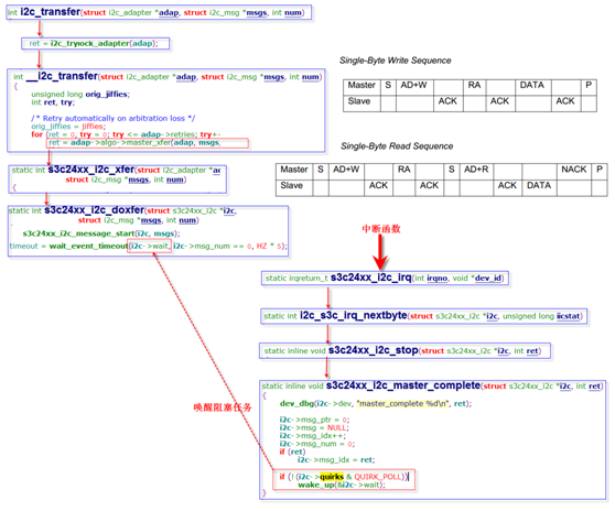
以下是一次i2c_msg传输的中断模式的大概步骤:

1. i2c_transfer()首先通过函数i2c_trylock_adapter()尝试获得adapter的控制权。如果adapter正在忙则返回错误信息;
2. __i2c_transfer()通过调用方法adap->algo->master_xfer(adap, msgs, num)传输i2c_msg,如果失败会尝试重新传送,重传次数最多adap->retries;
3. adap->algo->master_xfer()就是函数s3c24xx_i2c_xfer(),该函数最终调用 s3c24xx_i2c_doxfer(i2c, msgs, num)传输信息;
4. s3c24xx_i2c_doxfer()通过函数 s3c24xx_i2c_message_start(i2c, msgs)产生S和AD+W的信号,然后通过函数wait_event_timeout( )阻塞在等待队列i2c->wait上;
5. 右上角时序mpu6050的写和读的时序,从设备回复ACK和DATA都会发送中断信号给CPU。每次中断都会调用s3c24xx_i2c_irq->i2c_s3c_irq_nextbyte,
6. 最后一次中断,所有数据发送或读取完毕会调用s3c24xx_i2c_stop->s3c24xx_i2c_master_complete,通过wake_up唤醒阻塞在等待队列i2c->wait上的任务。
详细的代码流程如下:
-
i2c_transfer()首先通过函数i2c_trylock_adapter()尝试获得adapter的控制权。如果adapter正在忙则返回错误信息;
-
__i2c_transfer()通过调用方法adap->algo->master_xfer(adap,msgs, num)传输i2c_msg,如果失败会尝试重新传送,重传次数最多adap->retries;
-
adap->algo->master_xfer()就是函数s3c24xx_i2c_xfer(),该函数最终调用 s3c24xx_i2c_doxfer(i2c, msgs, num)传输信息;
-
s3c24xx_i2c_doxfer()通过函数 s3c24xx_i2c_message_start(i2c, msgs)产生S和AD+W的信号,然后通过函数wait_event_timeout()阻塞在等待队列i2c->wait上;
-
右上角时序mpu6050的写和读的时序,从设备回复ACK和DATA都会发送中断信号给CPU。每次中断都会调用s3c24xx_i2c_irq->i2c_s3c_irq_nextbyte,
-
最后一次中断,所有数据发送或读取完毕会调用s3c24xx_i2c_stop->s3c24xx_i2c_master_complete,通过wake_up唤醒阻塞在等待队列i2c->wait上的任务。
详细的代码流程如下:
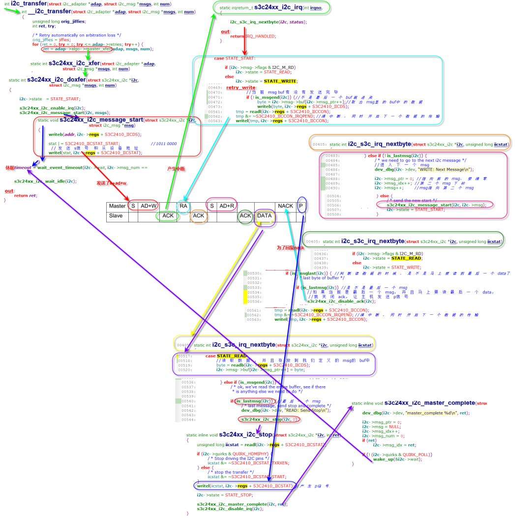
对着可以根据上图代码行号一步步去跟代码,涉及到寄存器设置可以参考第一章的寄存器使用截图。
审核编辑:郭婷
-
MPU6050教程开源分享2023-06-25 1782
-
MPU6050数据手册2022-03-09 2702
-
MPU6050的相关资料推荐2022-02-10 1626
-
MPU6050简介2021-12-06 2392
-
MPU6050模块2021-08-09 3119
-
mpu6050怎么与单片机连接2018-03-09 27626
-
一文看懂mpu6500和mpu6050区别2018-03-08 101082
-
Arduino与MPU6050的通信2017-11-07 8729
-
MPU6050(硬件IIC)2017-04-02 3074
-
MPU6050原理图2016-03-24 2537
-
MPU6050程序2015-12-15 1033
全部0条评论

快来发表一下你的评论吧 !

