

防火墙在广电出口安全方案中的应用
描述
一、方案简介
广电行业除了提供家庭广播电视业务,还向ISP租用链路开展宽带用户上网、服务器托管等网络接入服务。此时网络出口处通常部署防火墙作为出口网关提供Internet接入及安全保障功能。
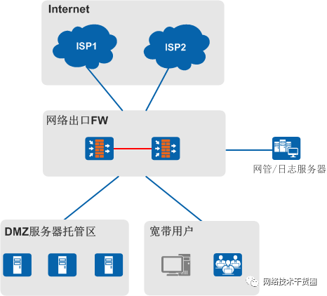
图1 防火墙在广电网络出口的应用
如图1所示,防火墙部署在网络出口主要提供如下功能:
NAT:提供源NAT功能将宽带用户私网IP转换为公网IP,提供NAT Server功能将托管服务器的私网IP转换为公网IP供外网用户访问。
多出口智能选路:提供基于目的IP、应用等多种选路措施,合理利用多条ISP链路保证上网质量。
安全管理:通过安全区域及安全策略进行区域隔离,提供入侵防御、DDoS攻击防范等安全功能进行安全防护。
用户溯源和审计:记录用户NAT前后IP地址、端口等日志发往日志服务器,满足相关部门的审计和溯源需求。
二、方案设计
2.1 典型组网
如图2所示,广电向两个ISP各租用了两条链路,为城域网的广电用户提供宽带上网服务。广电还在服务器区部署了服务器,为内外网用户提供服务器托管业务。
广电的Internet出口处部署了两台防火墙双机热备组网(主备方式)。两台防火墙的上行接口通过出口汇聚交换机与两个ISP相连,下行接口通过核心路由器与城域网相连,通过服务器区的交换机与服务器相连。
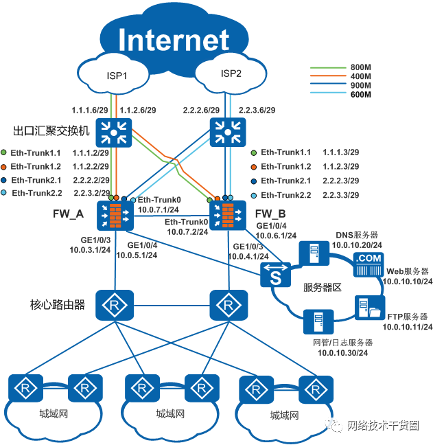
图2 防火墙在广电网络出口的典型组网
广电网络对Internet出口防火墙的具体需求如下:
两台防火墙能够组成主备备份组网,提升网络可靠性。
通过防火墙的源NAT功能保证城域网的海量用户能够同时访问Internet。
为了提升内网用户的宽带上网体验,广电的出口选路需求如下:
能够根据目的地址所属的ISP进行选路。例如,访问ISP1的服务器的流量能够通过ISP1链路转发,访问ISP2的服务器的流量能够通过ISP2链路转发。
属于同一个ISP的流量在两条链路间按权重负载分担。
引导P2P流量由资费较低、带宽较大的ISP2链路转发。
托管的服务器能够供外网用户访问,对服务器进行管理。
广电网络内还部署了DNS服务器为以上服务器提供域名解析。广电希望各ISP的外网用户能够解析到自己ISP为服务器分配的地址,从而提高访问服务器的速度。
防火墙能够保护内部网络,防止各种DDoS攻击,并对僵尸、木马、蠕虫等网络入侵行为进行告警。
为了应对有关部门的审查,防火墙能够提供内网用户访问Internet的溯源功能,包括NAT转换前后的IP地址、端口等。
2.2 业务规划
2.2.1 设备规划
广电网络出口可能用到的设备如表1所示,USG9500和USG6000如有差异将补充说明。

表1 广电网络出口设备规划
2.2.2 双机热备规划
由于一个ISP接入点无法与两台防火墙直接相连,因此需要在防火墙与ISP之间部署出口汇聚交换机。出口汇聚交换机可以将ISP的一条链路变为两条链路,然后分别将两条链路与两台防火墙的上行接口相连。而防火墙与下行路由器之间运行OSPF,所以这就组成了“两台防火墙上行连接交换机,下行连接路由器”的典型双机热备组网。该种组网方式防火墙上行配置VRRP备份组,下行配置VGMP组监控业务口。
双机热备组网可以转换为图3,将与同一个ISP接入点连接的主备防火墙接口加入同一个VRRP备份组。
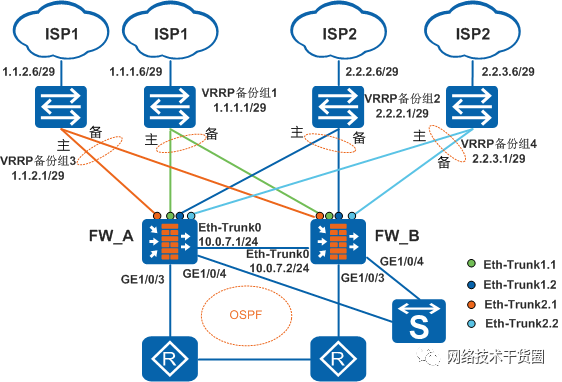
图3 双机热备组网
2.2.3 多出口选路规划
广电向不同运营商租用链路,多出口选路功能尤为重要,防火墙提供丰富的多出口功能满足需求:
通过DNS透明代理分担内网用户上网的DNS请求,从而达到在多个ISP间分担流量的目的。
内网用户上网的第一步是用户访问某个域名,DNS服务器将域名解析为IP地址。这一步存在一个问题,内网PC往往都配置了同一个ISP的DNS服务器,这样将导致用户只能解析到一个ISP的地址,后续的ISP选路也就无从谈起了。防火墙提供DNS透明代理功能解决这一问题,防火墙通过一定的规则将内网用户的DNS请求分担至不同ISP的DNS服务器,从而解析到不同ISP的地址。本例采取指定链路权重的方式分担DNS请求。
通过基于多出口的策略路由实现ISP选路。
防火墙的策略路由可以同时指定多个出接口,并配置多个出接口的流量分担方式。例如指定目的地址为ISP1地址的流量从ISP1的两个出接口发送,同时指定两个出接口间按权重进行负载分担。
通过基于应用的策略路由将P2P流量引导至ISP2链路。
通过健康检查探测链路的可达性。
防火墙探测某个出接口到指定目的地址的链路健康状态,保证流量不会被转发到故障链路上。
2.2.4 源NAT规划
在FW配置源NAT使内网用户可以通过有限的公网IP地址访问Internet。
地址池
根据向ISP申请的公网IP地址,配置两个对应不同ISP的地址池,注意地址池中排除VRRP备份组的公网IP、服务器对外发布的公网IP。
NAPT(Network Address and Port Translation)
NAPT同时对IP地址和端口进行转换,内网用户访问Internet的报文到达防火墙后,报文的源地址会被NAT转换成公网地址,源端口会被NAT转换成随机的非知名端口。这样一个公网地址就可以同时被多个内网用户使用,实现了公网地址的复用,解决了海量用户同时访问Internet的问题。
NAT ALG
当防火墙既开启NAT功能,又需要转发多通道协议报文(例如FTP等)时,必须开启相应的NAT ALG功能。例如FTP、SIP、H323、RTSP和QQ等多通道协议。
2.2.5 NAT Server规划
广电的托管服务器业务主要开通网站托管业务,如某个学校的网站托管,同时还有公司内部的办公网,公司门户网站等。由于托管服务器部署在内网的DMZ区域,所以需要在防火墙上部署NAT server功能,将服务器的私网地址转换成公网地址,而且需要为不同的ISP用户提供不同的公网地址。
如果DNS服务器在内网,则需要配置智能DNS使外网用户可以获取最适合的服务器解析地址,即与用户属于同一ISP网络地址避免跨网络访问。
2.2.6 安全功能规划
缺省情况下FW拒绝所有流量通过,需要配置安全策略允许正常的业务访问。具体规划见下文的数据规划。
出口网关作为广电网络与外界通信的关口,需要配置入侵防御(IPS)、攻击防范等安全功能。
本案例使用缺省的IPS配置文件default,对检测到的入侵行为进行阻断;还可以选择配置文件ids先记录攻击日志不阻断,然后根据日志再配置具体的IPS配置文件。
2.2.6 用户溯源规划
通过与日志服务器配合完成用户溯源:
FW配置向日志服务器发送会话日志功能,会话日志中详细记录了会话的原始(即NAT转换前)源IP地址/端口、目的IP地址/端口,以及会话经过NAT转换后的源IP地址/端口和目的IP地址/端口等信息。
如果某个用户在外网发布了非法言论,管理员在日志服务器中根据该用户的公网IP地址追踪到其私网IP地址。
管理员根据企业内部的认证系统等追踪到具体用户账号。
2.2.7 数据规划
根据上述业务规划进行数据规划。
三、注意事项
3.1 License
IPS功能和智能DNS功能需要License支持,另外智能DNS功能需要加载内容安全组件包才能使用。
3.2 硬件要求
对于USG9500,IPS、基于应用的策略路由、智能DNS需要应用安全业务处理子卡(SPC-APPSEC-FW)在位,否则功能不可用。
使用IPS功能前,建议将IPS特征库升级到最新版本。
3.3 组网部署
为了避免心跳接口故障导致双机通信异常,心跳接口建议使用Eth-trunk接口。对于支持扩展多个接口卡的设备(具体支持情况,请查阅硬件指南),必须使用跨板Eth-Trunk接口,即一个Eth-Trunk的成员接口来自于不同的接口板,这样既提高了可靠性,又增加了备份通道的带宽。对于无接口扩展能力无法使用跨板Eth-Trunk的设备,可能存在一块接口卡故障导致所有HRP备份通道不可用、业务受损。
当双机热备与智能选路结合使用时,如果上行部署交换机运行VRRP,防火墙的上行物理接口必须配置与ISP路由器同一网段的公网IP地址,否则无法指定接口的gateway。gateway命令是智能选路、链路健康探测的必选配置。
如果上行是路由器则无此限制。
3.4 智能选路
防火墙在接口下提供gateway命令生成等价缺省路由,协议类型为UNR,路由优先级为70,低于静态路由的优先级(60)。配置了此命令后不能再手动配置多出口的静态等价路由
策略路由智能选路不能和IP欺骗攻击防范功能或URPF(Unicast Reverse Path Forwarding,单播逆向路径转发)功能一起使用。如果开启IP欺骗攻击防范功能或URPF功能,可能导致防火墙丢弃报文。
3.5 黑洞路由
防火墙支持为NAT地址池中的地址生成UNR(User Network Route)路由,该UNR路由的作用与黑洞路由的作用相同,可以防止路由环路,同时也可以引入到OSPF等动态路由协议中发布出去。对于NAT Server来说,如果指定了协议和端口,则还需要手工配置目的地址为公网地址的黑洞路由,使外网访问公网地址但没有匹配到Server-Map的报文匹配到黑洞路由后直接被丢弃,防止路由环路。
四、方案配置
4.1 配置接口和安全区域
4.1.1 背景信息
按下图配置接口和安全区域。
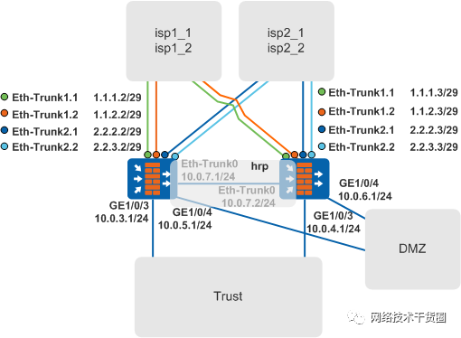
接口IP及安全区域
4.1.2 操作步骤
1.配置FW_A接口IP地址。
 system-view
[FW_A] interface Eth-Trunk 1
[FW_A-Eth-Trunk1] undo service-manage enable
[FW_A-Eth-Trunk1] description To-isp1
[FW_A-Eth-Trunk1] trunkport GigabitEthernet 1/0/1
[FW_A-Eth-Trunk1] trunkport GigabitEthernet 1/0/6
[FW_A-Eth-Trunk1] quit
[FW_A] interface Eth-Trunk 2
[FW_A-Eth-Trunk2] undo service-manage enable
[FW_A-Eth-Trunk2] description To-isp2
[FW_A-Eth-Trunk2] trunkport GigabitEthernet 1/0/2
[FW_A-Eth-Trunk2] trunkport GigabitEthernet 1/0/7
[FW_A-Eth-Trunk2] quit
[FW_A] interface Eth-Trunk 1.1
[FW_A-Eth-Trunk1.1] description To-isp1-1
[FW_A-Eth-Trunk1.1] vlan-type dot1q 11
[FW_A-Eth-Trunk1.1] ip address 1.1.1.2 29
[FW_A-Eth-Trunk1.1] quit
[FW_A] interface Eth-Trunk 2.1
[FW_A-Eth-Trunk2.1] description To-isp2-1
[FW_A-Eth-Trunk2.1] vlan-type dot1q 21
[FW_A-Eth-Trunk2.1] ip address 2.2.2.2 29
[FW_A-Eth-Trunk2.1] quit
[FW_A] interface Eth-Trunk 1.2
[FW_A-Eth-Trunk1.2] description To-isp1-2
[FW_A-Eth-Trunk1.2] vlan-type dot1q 12
[FW_A-Eth-Trunk1.2] ip address 1.1.2.2 29
[FW_A-Eth-Trunk1.2] quit
[FW_A] interface Eth-Trunk 2.2
[FW_A-Eth-Trunk2.2] description To-isp2-2
[FW_A-Eth-Trunk2.2] vlan-type dot1q 22
[FW_A-Eth-Trunk2.2] ip address 2.2.3.2 29
[FW_A-Eth-Trunk2.2] quit
[FW_A] interface GigabitEthernet 1/0/3
[FW_A-GigabitEthernet1/0/3] undo service-manage enable
[FW_A-GigabitEthernet1/0/3] description To-router
[FW_A-GigabitEthernet1/0/3] ip address 10.0.3.1 24
[FW_A-GigabitEthernet1/0/3] quit
[FW_A] interface GigabitEthernet 1/0/4
[FW_A-GigabitEthernet1/0/4] undo service-manage enable
[FW_A-GigabitEthernet1/0/4] description To-server
[FW_A-GigabitEthernet1/0/4] ip address 10.0.5.1 24
[FW_A-GigabitEthernet1/0/4] quit
[FW_A] interface Eth-Trunk 0
[FW_A-Eth-Trunk0] undo service-manage enable
[FW_A-Eth-Trunk0] description Hrp-interface
[FW_A-Eth-Trunk0] ip address 10.0.7.1 24
[FW_A-Eth-Trunk0] quit
[FW_A] interface GigabitEthernet 2/0/0
[FW_A-GigabitEthernet2/0/0] undo service-manage enable
[FW_A-GigabitEthernet2/0/0] eth-trunk 0
[FW_A-GigabitEthernet2/0/0] quit
[FW_A] interface GigabitEthernet 1/0/5
[FW_A-GigabitEthernet1/0/5] undo service-manage enable
[FW_A-GigabitEthernet1/0/5] eth-trunk 0
[FW_A-GigabitEthernet1/0/5] quit
2.将FW_A接口加入安全区域。
[FW_A] firewall zone name isp1_1
[FW_A-zone-isp1_1] set priority 10
[FW_A-zone-isp1_1] add interface Eth-Trunk 1.1
[FW_A-zone-isp1_1] quit
[FW_A] firewall zone name isp1_2
[FW_A-zone-isp1_2] set priority 15
[FW_A-zone-isp1_2] add interface Eth-Trunk 1.2
[FW_A-zone-isp1_2] quit
[FW_A] firewall zone name isp2_1
[FW_A-zone-isp2_1] set priority 20
[FW_A-zone-isp2_1] add interface Eth-Trunk 2.1
[FW_A-zone-isp2] quit
[FW_A] firewall zone name isp2_2
[FW_A-zone-isp2_2] set priority 25
[FW_A-zone-isp1_2] add interface Eth-Trunk 2.2
[FW_A-zone-isp2] quit
[FW_A] firewall zone trust
[FW_A-zone-trust] add interface GigabitEthernet 1/0/3
[FW_A-zone-trust] quit
[FW_A] firewall zone dmz
[FW_A-zone-dmz] add interface GigabitEthernet 1/0/4
[FW_A-zone-dmz] quit
[FW_A] firewall zone name hrp
[FW_A-zone-hrp] set priority 75
[FW_A-zone-hrp] add interface Eth-Trunk 0
[FW_A-zone-hrp] quit
3.参考上述步骤配置FW_B的接口IP和安全区域,不同之处是接口IP不同。
4.2 配置智能选路及路由
4.2.1 操作步骤
1.配置FW_A的健康检查功能,分别为ISP1和ISP2链路配置健康检查。
其中目的地址是Internet真实存在的IP地址,本例以ISP网关地址、DNS地址为例。
[FW_A] healthcheck enable
[FW_A] healthcheck name isp1_health1
[FW_A-healthcheck-isp1_health1] destination 1.1.1.6 interface Eth-Trunk1.1 protocol icmp
[FW_A-healthcheck-isp1_health1] destination 1.1.1.222 interface Eth-Trunk1.1 protocol dns
[FW_A-healthcheck-isp1_health1] quit
[FW_A] healthcheck name isp1_health2
[FW_A-healthcheck-isp1_health2] destination 1.1.2.6 interface Eth-Trunk1.2 protocol icmp
[FW_A-healthcheck-isp1_health2] destination 1.1.1.222 interface Eth-Trunk1.2 protocol dns
[FW_A-healthcheck-isp1_health2] quit
[FW_A] healthcheck name isp2_health1
[FW_A-healthcheck-isp2_health1] destination 2.2.2.6 interface Eth-Trunk2.1 protocol icmp
[FW_A-healthcheck-isp2_health1] destination 2.2.2.222 interface Eth-Trunk2.1 protocol dns
[FW_A-healthcheck-isp2_health1] quit
[FW_A] healthcheck name isp2_health2
[FW_A-healthcheck-isp2_health2] destination 2.2.3.6 interface Eth-Trunk2.2 protocol icmp
[FW_A-healthcheck-isp2_health2] destination 2.2.2.222 interface Eth-Trunk2.2 protocol dns
[FW_A-healthcheck-isp2_health2] quit
FW_B与FW_A的配置相同,请自行配置。
2.配置接口的网关地址、接口带宽并应用对应的健康检查。
接口应用健康检查功能后,当接口所在链路故障时,与其绑定的路由将失效。
[FW_A] interface Eth-Trunk 1.1
[FW_A-Eth-Trunk1.1] gateway 1.1.1.6
[FW_A-Eth-Trunk1.1] bandwidth ingress 800000
[FW_A-Eth-Trunk1.1] bandwidth egress 800000
[FW_A-Eth-Trunk1.1] healthcheck isp1_health1
[FW_A-Eth-Trunk1.1] quit
[FW_A] interface Eth-Trunk1.2
[FW_A-Eth-Trunk1.2] gateway 1.1.2.6
[FW_A-Eth-Trunk1.2] bandwidth ingress 400000
[FW_A-Eth-Trunk1.2] bandwidth egress 400000
[FW_A-Eth-Trunk1.2] healthcheck isp1_health2
[FW_A-Eth-Trunk1.2] quit
[FW_A] interface Eth-Trunk2.1
[FW_A-Eth-Trunk2.1] gateway 2.2.2.6
[FW_A-Eth-Trunk2.1] bandwidth ingress 900000
[FW_A-Eth-Trunk2.1] bandwidth egress 900000
[FW_A-Eth-Trunk2.1] healthcheck isp2_health1
[FW_A-Eth-Trunk2.1] quit
[FW_A] interface Eth-Trunk2.2
[FW_A-Eth-Trunk2.2] gateway 2.2.3.6
[FW_A-Eth-Trunk2.2] bandwidth ingress 600000
[FW_A-Eth-Trunk2.2] bandwidth egress 600000
[FW_A-Eth-Trunk2.2] healthcheck isp2_health2
[FW_A-Eth-Trunk2.2] quit
FW_B与FW_A的配置相同,请自行配置。
3.配置DNS透明代理。
a.配置DNS透明代理参数。
[FW_A] dns-transparent-policy
[FW_A-policy-dns] dns transparent-proxy enable
[FW_A-policy-dns] dns server bind interface Eth-Trunk1.1 preferred 1.1.1.222 alternate 1.1.1.223
[FW_A-policy-dns] dns server bind interface Eth-Trunk1.2 preferred 1.1.1.222 alternate 1.1.1.223
[FW_A-policy-dns] dns server bind interface Eth-Trunk2.1 preferred 2.2.2.222 alternate 2.2.2.223
[FW_A-policy-dns] dns server bind interface Eth-Trunk2.2 preferred 2.2.2.222 alternate 2.2.2.223
[FW_A-policy-dns] dns transparent-proxy exclude domain www.example.com server preferred 1.1.1.222
[FW_A-policy-dns] rule name dns_proxy
[FW_A-policy-dns-rule-dns_proxy] action tpdns
[FW_A-policy-dns-rule-dns_proxy] source-address 10.3.0.0 24
[FW_A-policy-dns-rule-dns_proxy] quit
[FW_A-policy-dns] quit
FW_B与FW_A的配置相同,请自行配置。
dns transparent-proxy exclude domain命令用来配置不需要DNS透明代理的域名,这里假设www.example.com固定使用1.1.1.222这个DNS服务器进行解析,不进行DNS透明代理。
b.配置基于DNS服务的策略路由使DNS请求按链路权重进行分担。
[FW_A] policy-based-route
[FW_A-policy-pbr] rule name dns_pbr
[FW_A-policy-pbr-rule-dns_pbr] ingress-interface GigabitEthernet1/0/3
[FW_A-policy-pbr-rule-dns_pbr] service dns
[FW_A-policy-pbr-rule-dns_pbr] action pbr egress-interface multi-interface
[FW_A-policy-pbr-rule-dns_pbr-multi-inter] add interface Eth-Trunk1.1 weight 2
[FW_A-policy-pbr-rule-dns_pbr-multi-inter] add interface Eth-Trunk1.2 weight 1
[FW_A-policy-pbr-rule-dns_pbr-multi-inter] add interface Eth-Trunk2.1 weight 3
[FW_A-policy-pbr-rule-dns_pbr-multi-inter] add interface Eth-Trunk2.2 weight 2
[FW_A-policy-pbr-rule-dns_pbr-multi-inter] mode proportion-of-weight
[FW_A-policy-pbr-rule-dns_pbr-multi-inter] quit
[FW_A-policy-pbr-rule-dns_pbr] quit
FW_B与FW_A的配置相同,请自行配置。
4.配置策略路由智能选路。
a.按如下格式准备ISP1和ISP2的地址文件,isp1.csv和isp2.csv。
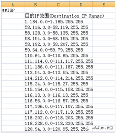
b.上传ISP地址文件到FW_A。
c.为ISP1和ISP2分别创建运营商名称isp1和isp2,并关联对应的ISP地址文件。
[FW_A] isp name isp1 set filename isp1.csv
[FW_A] isp name isp2 set filename isp2.csv
完成此配置后,防火墙自动生成以ISP名称命名的地址集,地址集中包含对应ISP的地址。该地址集中的内容不能直接修改,只能通过重新导入ISP地址文件进行间接修改。ISP地址集可以被策略路由引用,作为源地址或目的地址。
FW_B与FW_A的配置相同,请自行配置。
d.配置基于应用的策略路由,引导P2P流量从ISP2转发。
[FW_A] policy-based-route
[FW_A-policy-pbr] rule name p2p_pbr
[FW_A-policy-pbr-rule-p2p_pbr] ingress-interface GigabitEthernet1/0/3
[FW_A-policy-pbr-rule-p2p_pbr] application app BT Thunder eDonkey_eMule
[FW_A-policy-pbr-rule-p2p_pbr] action pbr egress-interface multi-interface
[FW_A-policy-pbr-rule-p2p_pbr-multi-inter] add interface Eth-Trunk2.1 weight 3
[FW_A-policy-pbr-rule-p2p_pbr-multi-inter] add interface Eth-Trunk2.2 weight 2
[FW_A-policy-pbr-rule-p2p_pbr-multi-inter] mode proportion-of-weight
[FW_A-policy-pbr-rule-p2p_pbr-multi-inter] quit
[FW_A-policy-pbr-rule-p2p_pbr] quit
多条策略路由规则的匹配顺序是按配置顺序匹配。本例配置了多条策略路由规则,注意先配置基于DNS服务和P2P应用的策略路由,再配置基于目的地址的策略路由,否则将先匹配基于目的地址的策略路由,基于DNS服务和P2P应用的策略路由就不生效了。
此处仅给出了BT、迅雷和电驴应用作为例子,具体配置时请根据实际需求指定应用。
FW_B与FW_A的配置相同,请自行配置。
e.配置基于ISP1地址为目的地址的策略路由,引导访问ISP1的流量从ISP1链路转发。
[FW_A-policy-pbr] rule name isp1_pbr
[FW_A-policy-pbr-rule-isp1_pbr] ingress-interface GigabitEthernet1/0/3
[FW_A-policy-pbr-rule-isp1_pbr] destination-address isp isp1
[FW_A-policy-pbr-rule-isp1_pbr] action pbr egress-interface multi-interface
[FW_A-policy-pbr-rule-isp1_pbr-multi-inter] add interface Eth-Trunk1.1 weight 2
[FW_A-policy-pbr-rule-isp1_pbr-multi-inter] add interface Eth-Trunk1.2 weight 1
[FW_A-policy-pbr-rule-isp1_pbr-multi-inter] mode proportion-of-weight
[FW_A-policy-pbr-rule-isp1_pbr-multi-inter] quit
[FW_A-policy-pbr-rule-isp1_pbr] quit
FW_B与FW_A的配置相同,请自行配置。
f.配置基于ISP2地址为目的地址的策略路由,引导访问ISP2的流量从ISP1链路转发。
[FW_A-policy-pbr] rule name isp2_pbr
[FW_A-policy-pbr-rule-isp2_pbr] ingress-interface GigabitEthernet1/0/3
[FW_A-policy-pbr-rule-isp2_pbr] destination-address isp isp2
[FW_A-policy-pbr-rule-isp2_pbr] action pbr egress-interface multi-interface
[FW_A-policy-pbr-rule-isp2_pbr-multi-inter] add interface Eth-Trunk2.1 weight 3
[FW_A-policy-pbr-rule-isp2_pbr-multi-inter] add interface Eth-Trunk2.2 weight 2
[FW_A-policy-pbr-rule-isp2_pbr-multi-inter] mode proportion-of-weight
[FW_A-policy-pbr-rule-isp2_pbr-multi-inter] quit
[FW_A-policy-pbr-rule-isp2_pbr] quit
FW_B与FW_A的配置相同,请自行配置。
5.配置OSPF。
a.在FW_A上配置OSPF,发布下行接口所在网段。
[FW_A] ospf 1
[FW_A-ospf-1] area 0
[FW_A-ospf-1-area-0.0.0.0] network 10.0.3.0 0.0.0.255
[FW_A-ospf-1-area-0.0.0.0] network 10.0.5.0 0.0.0.255
[FW_A-ospf-1-area-0.0.0.0] quit
[FW_A-ospf-1] quit
b.在FW_B上配置OSPF,发布下行接口所在网段。
[FW_B] ospf 1
[FW_B-ospf-1] area 0
[FW_B-ospf-1-area-0.0.0.0] network 10.0.4.0 0.0.0.255
[FW_B-ospf-1-area-0.0.0.0] network 10.0.6.0 0.0.0.255
[FW_B-ospf-1-area-0.0.0.0] quit
[FW_B-ospf-1] quit
4.3 配置双机热备
4.3.1 背景信息
按下图配置双机热备。
双机热备
4.3.2 操作步骤
1.在FW_A的上行接口上配置VRRP备份组,并将VRRP备份组状态设置为Active。
 system-view
[FW_A] interface Eth-Trunk 1.1
[FW_A-Eth-Trunk1.1] vrrp vrid 1 virtual-ip 1.1.1.1 29 active
[FW_A-Eth-Trunk1.1] quit
[FW_A] interface Eth-Trunk 2.1
[FW_A-Eth-Trunk2.1] vrrp vrid 2 virtual-ip 2.2.2.1 29 active
[FW_A-Eth-Trunk2.1] quit
[FW_A] interface Eth-Trunk 1.2
[FW_A-Eth-Trunk1.2] vrrp vrid 3 virtual-ip 1.1.2.1 29 active
[FW_A-Eth-Trunk1.2] quit
[FW_A] interface Eth-Trunk 2.2
[FW_A-Eth-Trunk2.2] vrrp vrid 4 virtual-ip 2.2.3.1 29 active
[FW_A-Eth-Trunk2.2] quit
2.在FW_A上配置VGMP组监控下行接口。
[FW_A] hrp track interface GigabitEthernet 1/0/3
[FW_A] hrp track interface GigabitEthernet 1/0/4
3.在FW_A配置根据VGMP状态调整OSPF Cost值功能。
[FW_A] hrp adjust ospf-cost enable
4.在FW_A上开启抢占功能,并配置抢占延迟时间为300s。
[FW_A] hrp preempt delay 300
5.在FW_A上指定心跳口,并启用双机热备。
[FW_A] hrp interface Eth-Trunk0 remote 10.0.7.2
[FW_A] hrp enable
6.参考上述步骤配置FW_B的双机热备功能,不同之处是VRRP备份组状态设置为Standby、hrp interface的远端地址设置为10.0.7.1。
7.配置路由器和交换机。
a.在路由器上配置OSPF,发布相邻网段,具体配置命令请参考路由器的相关文档。
b.在交换机上将三个接口加入同一个VLAN,具体配置命令请参考交换机的相关文档。
4.3.3 操作结果
至此,双机热备关系已经建立,后续大部分配置都能够备份。所以在下面的步骤中,我们只需在主用设备FW_A上配置即可(有特殊说明的配置除外)。
4.4 配置源NAT
4.4.1 操作步骤
1.配置NAT地址池pool_isp1_1,并指定地址池类型为NAPT。
HRP_M[FW_A] nat address-group pool_isp1_1
HRP_M[FW_A-address-group-pool_isp1_1] mode pat
HRP_M[FW_A-address-group-pool_isp1_1] section 1.1.1.10 1.1.1.12
HRP_M[FW_A-address-group-pool_isp1_1] route enable
HRP_M[FW_A-address-group-pool_isp1_1] quit
route enable命令将会为NAT地址池中的地址生成UNR(User Network Route)路由,该UNR路由的作用与黑洞路由的作用相同,可以防止路由环路,
2.配置Trust与isp1_1区域之间的NAT策略,将来自Trust区域用户报文的源地址转换成地址池pool_isp1_1中的地址。
HRP_M[FW_A] nat-policy
HRP_M[FW_A-policy-nat] rule name policy_nat1
HRP_M[FW_A-policy-nat-rule-policy_nat1] source-zone trust
HRP_M[FW_A-policy-nat-rule-policy_nat1] destination-zone isp1_1
HRP_M[FW_A-policy-nat-rule-policy_nat1] action source-nat address-group pool_isp1_1
HRP_M[FW_A-policy-nat-rule-policy_nat1] quit
HRP_M[FW_A-policy-nat] quit
3.配置NAT地址池pool_isp1_2,并指定地址池类型为NAPT。
HRP_M[FW_A] nat address-group pool_isp1_2
HRP_M[FW_A-address-group-pool_isp1_2] mode pat
HRP_M[FW_A-address-group-pool_isp1_2] section 1.1.2.10 1.1.2.12
HRP_M[FW_A-address-group-pool_isp1_2] route enable
HRP_M[FW_A-address-group-pool_isp1_2] quit
4.配置Trust与isp1_2区域之间的NAT策略,将来自Trust区域用户报文的源地址转换成地址池pool_isp1_2中的地址。
HRP_M[FW_A] nat-policy
HRP_M[FW_A-policy-nat] rule name policy_nat2
HRP_M[FW_A-policy-nat-rule-policy_nat2] source-zone trust
HRP_M[FW_A-policy-nat-rule-policy_nat2] destination-zone isp1_2
HRP_M[FW_A-policy-nat-rule-policy_nat2] action source-nat address-group pool_isp1_2
HRP_M[FW_A-policy-nat-rule-policy_nat2] quit
HRP_M[FW_A-policy-nat] quit
5.配置NAT地址池pool_isp2_1,并指定地址池类型为NAPT。
HRP_M[FW_A] nat address-group pool_isp2_1
HRP_M[FW_A-address-group-pool_isp2_1] mode pat
HRP_M[FW_A-address-group-pool_isp2_1] section 2.2.2.10 2.2.2.12
HRP_M[FW_A-address-group-pool_isp2_1] route enable
HRP_M[FW_A-address-group-pool_isp2_1] quit
6.配置Trust与isp2_1区域之间的NAT策略,将来自Trust区域用户报文的源地址转换成地址池pool_isp2_1中的地址。
HRP_M[FW_A] nat-policy
HRP_M[FW_A-policy-nat] rule name policy_nat3
HRP_M[FW_A-policy-nat-rule-policy_nat3] source-zone trust
HRP_M[FW_A-policy-nat-rule-policy_nat3] destination-zone isp2_1
HRP_M[FW_A-policy-nat-rule-policy_nat3] action source-nat address-group pool_isp2_1
HRP_M[FW_A-policy-nat-rule-policy_nat3] quit
HRP_M[FW_A-policy-nat] quit
7.配置NAT地址池pool_isp2_2,并指定地址池类型为NAPT。
HRP_M[FW_A] nat address-group pool_isp2_2
HRP_M[FW_A-address-group-pool_isp2_2] mode pat
HRP_M[FW_A-address-group-pool_isp2_2] section 2.2.3.10 2.2.3.12
HRP_M[FW_A-address-group-pool_isp2_2] route enable
HRP_M[FW_A-address-group-pool_isp2_2] quit
8.配置Trust与isp2_2区域之间的NAT策略,将来自Trust区域用户报文的源地址转换成地址池pool_isp2_2中的地址。
HRP_M[FW_A] nat-policy
HRP_M[FW_A-policy-nat] rule name policy_nat4
HRP_M[FW_A-policy-nat-rule-policy_nat4] source-zone trust
HRP_M[FW_A-policy-nat-rule-policy_nat4] destination-zone isp2_2
HRP_M[FW_A-policy-nat-rule-policy_nat4] action source-nat address-group pool_isp2_2
HRP_M[FW_A-policy-nat-rule-policy_nat4] quit
HRP_M[FW_A-policy-nat] quit
9.配置NAT ALG功能。
HRP_M[FW_A] detect ftp

HRP_M[FW_A] detect sip

HRP_M[FW_A] detect h323

HRP_M[FW_A] detect rtsp

HRP_M[FW_A] detect qq
4.5 配置NAT Server和智能DNS
4.5.1 背景信息
智能DNS受内容安全组合License控制,并且通过动态加载功能加载相应组件包后方可使用。
对于USG9500,智能DNS需要应用安全业务处理子卡(SPC-APPSEC-FW)在位,否则功能不可用。
4.5.2 操作步骤
1.配置NAT Server。
a.配置NAT Server功能,将Web服务器的私网地址分别映射成供ISP1和ISP2用户访问的公网地址。
HRP_M[FW_A] nat server policy_web1 zone isp1_1 protocol tcp global 1.1.1.15 8080 inside 10.0.10.10 www
HRP_M[FW_A] nat server policy_web2 zone isp1_2 protocol tcp global 1.1.2.15 8080 inside 10.0.10.10 www
HRP_M[FW_A] nat server policy_web3 zone isp2_1 protocol tcp global 2.2.2.15 8080 inside 10.0.10.10 www
HRP_M[FW_A] nat server policy_web4 zone isp2_2 protocol tcp global 2.2.3.15 8080 inside 10.0.10.10 www
b.配置NAT Server功能,将FTP服务器的私网地址分别映射成供ISP1和ISP2用户访问的公网地址。
HRP_M[FW_A] nat server policy_ftp1 zone isp1_1 protocol tcp global 1.1.1.16 ftp inside 10.0.10.11 ftp
HRP_M[FW_A] nat server policy_ftp2 zone isp1_2 protocol tcp global 1.1.2.16 ftp inside 10.0.10.11 ftp
HRP_M[FW_A] nat server policy_ftp3 zone isp2_1 protocol tcp global 2.2.2.16 ftp inside 10.0.10.11 ftp
HRP_M[FW_A] nat server policy_ftp4 zone isp2_2 protocol tcp global 2.2.3.16 ftp inside 10.0.10.11 ftp
c.配置NAT Server功能,将DNS服务器的私网地址分别映射成供ISP1和ISP2用户访问的公网地址。
HRP_M[FW_A] nat server policy_dns1 zone isp1_1 protocol tcp global 1.1.1.17 domain inside 10.0.10.20 domain
HRP_M[FW_A] nat server policy_dns2 zone isp1_2 protocol tcp global 1.1.2.17 domain inside 10.0.10.20 domain
HRP_M[FW_A] nat server policy_dns3 zone isp2_1 protocol tcp global 2.2.2.17 domain inside 10.0.10.20 domain
HRP_M[FW_A] nat server policy_dns4 zone isp2_2 protocol tcp global 2.2.3.17 domain inside 10.0.10.20 domain
2.配置源进源出功能。
在接口上配置IP地址和网关地址后,才能配置源进源出功能。IP地址和网关地址已经在配置接口和安全区域和配置智能选路及路由中配置完成。
接口下配置不支持备份,因此需要同时在FW_A和FW_B上配置源进源出功能。
HRP_M[FW_A] interface Eth-Trunk 1.1
HRP_M[FW_A-Eth-Trunk1.1] redirect-reverse next-hop 1.1.1.6
HRP_M[FW_A-Eth-Trunk1.1] quit
HRP_M[FW_A] interface Eth-Trunk 2.1
HRP_M[FW_A-Eth-Trunk2.1] redirect-reverse next-hop 2.2.2.6
HRP_M[FW_A-Eth-Trunk2.1] quit
HRP_M[FW_A] interface Eth-Trunk 1.2
HRP_M[FW_A-Eth-Trunk1.2] redirect-reverse next-hop 1.1.2.6
HRP_M[FW_A-Eth-Trunk1.2] quit
HRP_M[FW_A] interface Eth-Trunk 2.2
HRP_M[FW_A-Eth-Trunk2.2] redirect-reverse next-hop 2.2.3.6
HRP_M[FW_A-Eth-Trunk2.2] quit
HRP_S[FW_B] interface Eth-Trunk 1.1
HRP_S[FW_B-Eth-Trunk1.1] redirect-reverse next-hop 1.1.1.6
HRP_S[FW_B-Eth-Trunk1.1] quit
HRP_S[FW_B] interface Eth-Trunk 2.1
HRP_S[FW_B-Eth-Trunk2.1] redirect-reverse next-hop 2.2.2.6
HRP_S[FW_B-Eth-Trunk2.1] quit
HRP_S[FW_B] interface Eth-Trunk 1.2
HRP_S[FW_B-Eth-Trunk1.2] redirect-reverse next-hop 1.1.2.6
HRP_S[FW_B-Eth-Trunk1.2] quit
HRP_S[FW_B] interface Eth-Trunk 2.2
HRP_S[FW_B-Eth-Trunk2.2] redirect-reverse next-hop 2.2.3.6
HRP_S[FW_B-Eth-Trunk2.2] quit
3.配置智能DNS。
DNS服务器部署在内网且记录了Web和FTP服务器域名与公网IP地址的对应关系,此时配置智能DNS功能,确保各个ISP的用户访问内网服务器时,都能够解析到自己ISP为服务器分配的地址,从而提高访问速度。例如使ISP1的用户访问内网的Web服务器10.0.10.10时,能够解析到服务器的ISP1地址1.1.1.15, ISP2的用户访问内网的Web服务器10.0.10.10时,能够解析到服务器的ISP2地址2.2.2.15。
HRP_M[FW_A] dns-smart enable
HRP_M[FW_A] dns-smart group 1 type multi
HRP_M[FW_A-dns-smart-group-1] out-interface Eth-Trunk 1.1 map 1.1.1.15
HRP_M[FW_A-dns-smart-group-1] out-interface Eth-Trunk 2.1 map 2.2.2.15
HRP_M[FW_A-dns-smart-group-1] out-interface Eth-Trunk 1.2 map 1.1.2.15
HRP_M[FW_A-dns-smart-group-1] out-interface Eth-Trunk 2.2 map 2.2.3.15
HRP_M[FW_A-dns-smart-group-1] quit
HRP_M[FW_A] dns-smart group 2 type multi
HRP_M[FW_A-dns-smart-group-2] out-interface Eth-Trunk 1.1 map 1.1.1.16
HRP_M[FW_A-dns-smart-group-2] out-interface Eth-Trunk 2.1 map 2.2.2.16
HRP_M[FW_A-dns-smart-group-2] out-interface Eth-Trunk 1.2 map 1.1.2.16
HRP_M[FW_A-dns-smart-group-2] out-interface Eth-Trunk 2.2 map 2.2.3.16
HRP_M[FW_A-dns-smart-group-2] quit
4.配置NAT Server公网地址的黑洞路由,避免防火墙与ISP路由器之间产生路由环路。
路由配置不支持备份,因此需要同时在FW_A和FW_B上配置。
HRP_M[FW_A] ip route-static 1.1.1.15 32 NULL 0
HRP_M[FW_A] ip route-static 1.1.1.16 32 NULL 0
HRP_M[FW_A] ip route-static 1.1.1.17 32 NULL 0
HRP_M[FW_A] ip route-static 2.2.2.15 32 NULL 0
HRP_M[FW_A] ip route-static 2.2.2.16 32 NULL 0
HRP_M[FW_A] ip route-static 2.2.2.17 32 NULL 0
HRP_M[FW_A] ip route-static 1.1.2.15 32 NULL 0
HRP_M[FW_A] ip route-static 1.1.2.16 32 NULL 0
HRP_M[FW_A] ip route-static 1.1.2.17 32 NULL 0
HRP_M[FW_A] ip route-static 2.2.3.15 32 NULL 0
HRP_M[FW_A] ip route-static 2.2.3.16 32 NULL 0
HRP_M[FW_A] ip route-static 2.2.3.17 32 NULL 0
HRP_S[FW_B] ip route-static 1.1.1.15 32 NULL 0
HRP_S[FW_B] ip route-static 1.1.1.16 32 NULL 0
HRP_S[FW_B] ip route-static 1.1.1.17 32 NULL 0
HRP_S[FW_B] ip route-static 2.2.2.15 32 NULL 0
HRP_S[FW_B] ip route-static 2.2.2.16 32 NULL 0
HRP_S[FW_B] ip route-static 2.2.2.17 32 NULL 0
HRP_S[FW_B] ip route-static 1.1.2.15 32 NULL 0
HRP_S[FW_B] ip route-static 1.1.2.16 32 NULL 0
HRP_S[FW_B] ip route-static 1.1.2.17 32 NULL 0
HRP_S[FW_B] ip route-static 2.2.3.15 32 NULL 0
HRP_S[FW_B] ip route-static 2.2.3.16 32 NULL 0
HRP_S[FW_B] ip route-static 2.2.3.17 32 NULL 0
4.6 配置安全策略及安全防护
4.6.1 操作步骤
1.配置Trust区域到isp1_1、isp1_2区域的安全策略,允许内网用户通过ISP1访问Internet,并进行入侵防御检测。
HRP_M[FW_A] security-policy
HRP_M[FW_A-policy-security] rule name trust_to_isp1
HRP_M[FW_A-policy-security-rule-trust_to_isp1] source-zone trust
HRP_M[FW_A-policy-security-rule-trust_to_isp1] destination-zone isp1_1 isp1_2
HRP_M[FW_A-policy-security-rule-trust_to_isp1] profile ips default
HRP_M[FW_A-policy-security-rule-trust_to_isp1] action permit
HRP_M[FW_A-policy-security-rule-trust_to_isp1] quit
2.配置Trust区域到isp2_1、isp2_2区域的安全策略,允许内网用户通过ISP2访问Internet,并进行入侵防御检测。
HRP_M[FW_A-policy-security] rule name trust_to_isp2
HRP_M[FW_A-policy-security-rule-trust_to_isp2] source-zone trust
HRP_M[FW_A-policy-security-rule-trust_to_isp2] destination-zone isp2_1 isp2_2
HRP_M[FW_A-policy-security-rule-trust_to_isp2] profile ips default
HRP_M[FW_A-policy-security-rule-trust_to_isp2] action permit
HRP_M[FW_A-policy-security-rule-trust_to_isp2] quit
3.配置isp1_1、isp1_2区域到DMZ区域的安全策略,允许外网用户通过ISP1链路访问DMZ区域的Web服务器、FTP服务器和DNS服务器,并进行入侵防御检测。
HRP_M[FW_A-policy-security] rule name isp1_to_http
HRP_M[FW_A-policy-security-rule-isp1_to_http] source-zone isp1_1 isp1_2
HRP_M[FW_A-policy-security-rule-isp1_to_http] destination-zone dmz
HRP_M[FW_A-policy-security-rule-isp1_to_http] destination-address 10.0.10.10 24
HRP_M[FW_A-policy-security-rule-isp1_to_http] service http
HRP_M[FW_A-policy-security-rule-isp1_to_http] profile ips default
HRP_M[FW_A-policy-security-rule-isp1_to_http] action permit
HRP_M[FW_A-policy-security-rule-isp1_to_http] quit
HRP_M[FW_A-policy-security] rule name isp1_to_ftp
HRP_M[FW_A-policy-security-rule-isp1_to_ftp] source-zone isp1_1 isp1_2
HRP_M[FW_A-policy-security-rule-isp1_to_ftp] destination-zone dmz
HRP_M[FW_A-policy-security-rule-isp1_to_ftp] destination-address 10.0.10.11 24
HRP_M[FW_A-policy-security-rule-isp1_to_ftp] service ftp
HRP_M[FW_A-policy-security-rule-isp1_to_ftp] profile ips default
HRP_M[FW_A-policy-security-rule-isp1_to_ftp] action permit
HRP_M[FW_A-policy-security-rule-isp1_to_ftp] quit
HRP_M[FW_A-policy-security] rule name isp1_to_dns
HRP_M[FW_A-policy-security-rule-isp1_to_dns] source-zone isp1_1 isp1_2
HRP_M[FW_A-policy-security-rule-isp1_to_dns] destination-zone dmz
HRP_M[FW_A-policy-security-rule-isp1_to_dns] destination-address 10.0.10.20 24
HRP_M[FW_A-policy-security-rule-isp1_to_dns] service dns
HRP_M[FW_A-policy-security-rule-isp1_to_dns] profile ips default
HRP_M[FW_A-policy-security-rule-isp1_to_dns] action permit
HRP_M[FW_A-policy-security-rule-isp1_to_dns] quit
4.配置isp2_1、isp2_2区域到DMZ区域的安全策略,允许外网用户通过ISP2链路访问DMZ区域的Web服务器、FTP服务器和DNS服务器,并进行入侵防御检测。
HRP_M[FW_A-policy-security] rule name isp2_to_http
HRP_M[FW_A-policy-security-rule-isp2_to_http] source-zone isp2_1 isp2_2
HRP_M[FW_A-policy-security-rule-isp2_to_http] destination-zone dmz
HRP_M[FW_A-policy-security-rule-isp2_to_http] destination-address 10.0.10.10 24
HRP_M[FW_A-policy-security-rule-isp2_to_http] service http
HRP_M[FW_A-policy-security-rule-isp2_to_http] profile ips default
HRP_M[FW_A-policy-security-rule-isp2_to_http] action permit
HRP_M[FW_A-policy-security-rule-isp2_to_http] quit
HRP_M[FW_A-policy-security] rule name isp2_to_ftp
HRP_M[FW_A-policy-security-rule-isp2_to_ftp] source-zone isp2_1 isp2_2
HRP_M[FW_A-policy-security-rule-isp2_to_ftp] destination-zone dmz
HRP_M[FW_A-policy-security-rule-isp2_to_ftp] destination-address 10.0.10.11 24
HRP_M[FW_A-policy-security-rule-isp2_to_ftp] service ftp
HRP_M[FW_A-policy-security-rule-isp2_to_ftp] profile ips default
HRP_M[FW_A-policy-security-rule-isp2_to_ftp] action permit
HRP_M[FW_A-policy-security-rule-isp2_to_ftp] quit
HRP_M[FW_A-policy-security] rule name isp1_to_dns
HRP_M[FW_A-policy-security-rule-isp2_to_dns] source-zone isp2_1 isp2_2
HRP_M[FW_A-policy-security-rule-isp2_to_dns] destination-zone dmz
HRP_M[FW_A-policy-security-rule-isp2_to_dns] destination-address 10.0.10.20 24
HRP_M[FW_A-policy-security-rule-isp2_to_dns] service dns
HRP_M[FW_A-policy-security-rule-isp2_to_dns] profile ips default
HRP_M[FW_A-policy-security-rule-isp2_to_dns] action permit
HRP_M[FW_A-policy-security-rule-isp2_to_dns] quit
5.配置Trust区域到DMZ区域的安全策略,允许内网用户访问DMZ区域的Web服务器、FTP服务器和DNS服务器,并进行入侵防御检测。
HRP_M[FW_A-policy-security] rule name trust_to_http
HRP_M[FW_A-policy-security-rule-trust_to_http] source-zone trust
HRP_M[FW_A-policy-security-rule-trust_to_http] destination-zone dmz
HRP_M[FW_A-policy-security-rule-trust_to_http] destination-address 10.0.10.10 24
HRP_M[FW_A-policy-security-rule-trust_to_http] service http
HRP_M[FW_A-policy-security-rule-trust_to_http] profile ips default
HRP_M[FW_A-policy-security-rule-trust_to_http] action permit
HRP_M[FW_A-policy-security-rule-trust_to_http] quit
HRP_M[FW_A-policy-security] rule name trust_to_ftp
HRP_M[FW_A-policy-security-rule-trust_to_ftp] source-zone trust
HRP_M[FW_A-policy-security-rule-trust_to_ftp] destination-zone dmz
HRP_M[FW_A-policy-security-rule-trust_to_ftp] destination-address 10.0.10.11 24
HRP_M[FW_A-policy-security-rule-trust_to_ftp] service ftp
HRP_M[FW_A-policy-security-rule-trust_to_ftp] profile ips default
HRP_M[FW_A-policy-security-rule-trust_to_ftp] action permit
HRP_M[FW_A-policy-security-rule-trust_to_ftp] quit
HRP_M[FW_A-policy-security] rule name trust_to_dns
HRP_M[FW_A-policy-security-rule-trust_to_dns] source-zone trust
HRP_M[FW_A-policy-security-rule-trust_to_dns] destination-zone dmz
HRP_M[FW_A-policy-security-rule-trust_to_dns] destination-address 10.0.10.20 24
HRP_M[FW_A-policy-security-rule-trust_to_dns] service dns
HRP_M[FW_A-policy-security-rule-trust_to_dns] profile ips default
HRP_M[FW_A-policy-security-rule-trust_to_dns] action permit
HRP_M[FW_A-policy-security-rule-trust_to_dns] quit
6.配置Local到DMZ区域的安全策略,允许防火墙向与日志服务器发送日志。
HRP_M[FW_A-policy-security] rule name local_to_logcenter
HRP_M[FW_A-policy-security-rule-local_to_logcenter] source-zone local
HRP_M[FW_A-policy-security-rule-local_to_logcenter] destination-zone dmz
HRP_M[FW_A-policy-security-rule-local_to_logcenter] destination-address 10.0.10.30 24
HRP_M[FW_A-policy-security-rule-local_to_logcenter] action permit
HRP_M[FW_A-policy-security-rule-local_to_logcenter] quit
7.配置Local到isp1和isp2区域的安全策略,允许FW连接安全中心升级特征库、发送健康检查报文。
HRP_M[FW_A-policy-security] rule name local_to_isp
HRP_M[FW_A-policy-security-rule-local_to_isp] source-zone local
HRP_M[FW_A-policy-security-rule-local_to_isp] destination-zone isp1_1 isp1_2 isp2_1 isp2_2
HRP_M[FW_A-policy-security-rule-local_to_isp] action permit
HRP_M[FW_A-policy-security-rule-local_to_isp] quit
HRP_M[FW_A-policy-security] quit
对于USG6000&USG9500 V500R001C80之前的版本,需要在FW上配置对应的安全策略,允许FW向目的设备发送健康检查探测报文。对于V500R001C80及之后的版本,健康检查的探测报文不受安全策略控制,默认放行,无需配置相应安全策略。
8.入侵防御特征库和应用识别特征库自动升级。
a.确保防火墙已经激活支持入侵防御特征库升级服务器的License。
HRP_M[FW_A] display license
IPS        : Enabled;   service expire time: 2015/06/12
b.配置DNS服务器,使防火墙能通过域名访问安全中心。
HRP_M[FW_A] dns resolve
HRP_M[FW_A] dns server 1.1.1.222
c.配置特征库定时自动升级。
HRP_M[FW_A] update schedule ips-sdb enable
HRP_M[FW_A] update schedule sa-sdb enable
HRP_M[FW_A] update schedule ips-sdb daily 03:00
HRP_M[FW_A] update schedule sa-sdb weekly Mon 03:00
9.配置攻击防范。
HRP_M[FW_A] firewall defend land enable
HRP_M[FW_A] firewall defend smurf enable
HRP_M[FW_A] firewall defend fraggle enable
HRP_M[FW_A] firewall defend ip-fragment enable
HRP_M[FW_A] firewall defend tcp-flag enable
HRP_M[FW_A] firewall defend winnuke enable
HRP_M[FW_A] firewall defend source-route enable
HRP_M[FW_A] firewall defend teardrop enable
HRP_M[FW_A] firewall defend route-record enable
HRP_M[FW_A] firewall defend time-stamp enable
HRP_M[FW_A] firewall defend ping-of-death enable
4.7 配置用户溯源
4.7.1 背景信息
防火墙向eLog发送二进制会话日志、IM日志,eLog采集并存储、分析日志。根据这些日志可以获取用户NAT前的原始IP、IM上下线记录等满足审需求。
4.7.2 操作步骤
1.在FW_A上配置日志主机。
HRP_M[FW_A] firewall log host 1 10.0.10.30 9002
HRP_M[FW_A] firewall log source 10.0.5.1 6000
2.在FW_A的安全策略中开启会话日志功能记录功能。
HRP_M[FW_A] security-policy
HRP_M[FW_A-policy-security] rule name trust_to_isp1
HRP_M[FW_A-policy-security-rule-trust_to_isp1] session logging
HRP_M[FW_A-policy-security-rule-trust_to_isp1] quit
HRP_M[FW_A-policy-security] rule name trust_to_isp2
HRP_M[FW_A-policy-security-rule-trust_to_isp2] session logging
HRP_M[FW_A-policy-security-rule-trust_to_isp2] quit
HRP_M[FW_A-policy-security] quit
3.在FW_A上开启IM日志发送功能。
HRP_M[FW_A] firewall log im enable
4.在FW_B上配置向日志主机发送日志的源IP和端口,此配置不支持备份。
HRP_S[FW_B] firewall log source 10.0.6.1 6000
5.在FW_A上配置SNMP V3。
HRP_M[FW_A] snmp-agent sys-info version v3
HRP_M[FW_A] snmp-agent group v3 NMS1 privacy
HRP_M[FW_A] snmp-agent usm-user v3 admin1 group NMS1
HRP_M[FW_A] snmp-agent usm-user v3 admin1 authentication-mode md5 cipher Admin@123abcdefg1234567890abccba10
HRP_M[FW_A] snmp-agent usm-user v3 admin1 privacy-mode aes256 cipher Admin@123abcdefg1234567890abccba10
6.在FW_B上配置SNMP V3,此配置不支持备份。
HRP_S[FW_B] snmp-agent sys-info version v3
HRP_S[FW_B] snmp-agent group v3 NMS1 privacy
HRP_S[FW_B] snmp-agent usm-user v3 admin1 group NMS1
HRP_S[FW_B] snmp-agent usm-user v3 admin1 authentication-mode md5 cipher Admin@123abcdefg1234567890abccba10
HRP_S[FW_B] snmp-agent usm-user v3 admin1 privacy-mode aes256 cipher Admin@123abcdefg1234567890abccba10
7.eLog配置完成后,在eLog上选择“日志分析 > 会话分析 > IPv4会话日志”,可以查看会话日志。选择“日志分析 > 网络安全分析 > 即时通信”,可以查看IM日志。
4.8 查看流量统计
4.8.1 操作步骤
1.登录Web配置界面。
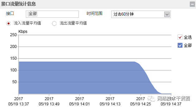
2.在面板中查看接口或整机流量趋势。
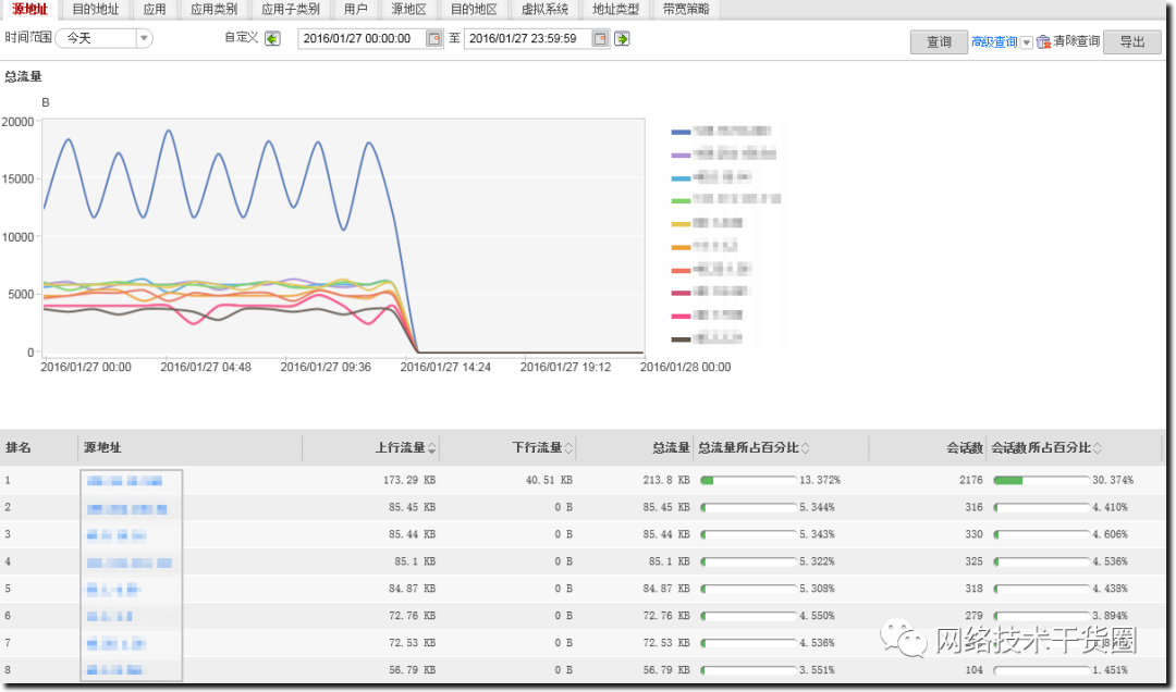
3.对于USG6000,如果安装有硬盘还可以选择“监控 > 报表 > 流量报表”查看流量报表。可以基于地址、应用等查询流量趋势。
4.9 结果验证
内网用户可以正常访问Internet。
外网用户可以通过公网IP访问内网服务器。
eLog可以获取防火墙会话日志。
在主防火墙的接口GigabitEthernet 1/0/1上执行shutdown命令,模拟链路故障,发现主备正常倒换,业务不会中断。
五、方案总结与建议
5.1 方案总结
本案例介绍了防火墙部署在广电网络出口的组网规划及部署,实际可以根据需求选择配置的功能。该方案有如下几点总结:
网络部署上采取了双机热备部署方式,上行连接交换机部署VRRP,下行连接路由器运行OSPF。实际还可能上行也部署出口路由器运行OSPF。本案例中的部署方式尤其注意防火墙上行接口需规划公网地址,否则无法指定接口网关。
多出口智能选路是广电出口的重要需求,本例通过如下方式实现需求:
出站:本例通过多出口策略路由实现了两个需求,目的地址属于哪个ISP就从哪条链路转发、属于同一个ISP的流量在该ISP的多条链路间按权重负载分担。
入站:配置NAT Server向不同ISP公布不同的服务器公网IP地址。同时如果为服务器提供域名解析的DNS服务器部署在内网,防火墙还提供了智能DNS功能使各ISP的外网用户能够解析到自己ISP为服务器分配的地址,从而提高访问服务器的速度。
5.2 其他配置建议
本例中使用了最常用的NAPT进行地址转换,如果网络中P2P流量较多可以选择配置三元组NAT节省二级运营商的运营资费。
文件共享、语音通信、视频等P2P应用的实现原理都是先从服务器获取对端的IP和端口,然后直接与对方建立连接。此时NAPT与P2P不能很好地共存。
例如:内网PC1首先和外网的P2P服务器进行交互(登录、认证等操作),防火墙会对PC1访问P2P服务器的报文进行NAPT方式的转换,P2P服务器记录PC1经过转换后的公网地址和端口。当PC2需要下载文件时,服务器会将PC1的地址和端口发给PC2,然后PC2从PC1上下载文件。但是因为PC2访问PC1无法匹配会话表而被防火墙拒绝访问,PC2就只能再向其他主机请求资源文件。
这样如果PC1和PC2都位于内网,PC2却只能向外网主机请求资源文件。这样当有大量的内网用户进行P2P下载时,这种业务就会占用很多运营商带宽,而且浪费了二级运营商的流量资费。同时,对于跨网络访问,用户的下载体验也不佳。
三元组NAT可以解决此问题,无论PC1是否访问过PC2,只要PC2获取到PC1经过NAT转换后的地址和端口,就可以主动向该地址和端口发起访问。防火墙上即使没有配置相应的安全策略,也允许此类访问报文通过。两台内网PC可以不通过外网直接进行P2P下载,节约了二级运营商的流量资费。
三元组NAT配置与NAPT配置差异不大,只是指定地址池类型为full-cone类型。
HRP_M[FW_A] nat address-group pool_isp1
HRP_M[FW_A-address-group-pool_isp1] mode full-cone global
HRP_M[FW_A-address-group-pool_isp1] section 1.1.1.10 1.1.1.12
HRP_M[FW_A-address-group-isp1] quit
对于USG9500配置三元组NAT前,必须保证HASH选板模式为源地址HASH模式。具体的配置命令如下:
[FW] firewall hash-mode source-only
配置完成后需要重新启动设备才能生效。
-
【电脑安全技巧】电脑防火墙的使用技巧2013-07-12 2831
-
发现 STM32 防火墙的安全配置2018-07-27 5457
-
防火墙多级安全参考模型的设计与实现2009-02-27 688
-
基于Linux 高校网络防火墙的设计2009-06-06 590
-
防火墙技术2009-06-16 878
-
基于Linux高校网络防火墙的设计2009-12-16 661
-
谈防火墙及防火墙的渗透技术2009-08-01 1327
-
究竟什么是防火墙?2010-02-24 894
-
防火墙的性能测试方案2010-11-16 3174
-
防火墙穿透技术及其应用探析2015-12-28 857
-
什么是数据库防火墙 数据库防火墙作用是什么2018-07-04 12228
-
什么是防火墙?防火墙如何工作?2020-09-30 6056
-
防火墙在云计算安全方案中的应用方案2022-11-02 2175
-
恒讯科技分析:什么是防火墙与下一代防火墙(NGFW)?2023-06-13 2120
-
云防火墙和web应用防火墙详细介绍2024-12-19 866
全部0条评论

快来发表一下你的评论吧 !
