

防火墙在云计算安全方案中的应用方案
描述
防火墙旁挂在云计算网络的核心交换机上,通过虚拟系统隔离网络中的虚拟机业务。同时,防火墙形成双机热备状态,提高业务的可靠性。
方案简介云计算网络简介
随着云计算的迅猛发展,企业可以便捷地接入云计算网络,获取服务器、存储、应用等资源,减少构建IT基础设施的投资成本,大大加快了信息化进程。
如图所示,某个“工业云”为企业用户提供云计算服务,网络中的业务包括如下几种:
企业用户访问虚拟机来获取定制化的资源。
企业用户访问Portal系统来进行帐号申请和虚拟机空间管理等操作。
云计算网络中的管理组件对虚拟机、Portal系统以及网络设备进行管理。
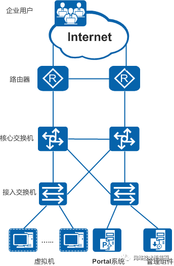
云计算网络示意图
防火墙在云计算网络中的应用
如图所示,防火墙旁挂在云计算网络中的核心交换机上,将虚拟机和Portal系统发布出去供企业用户访问,并且对企业用户访问虚拟机的业务进行隔离。
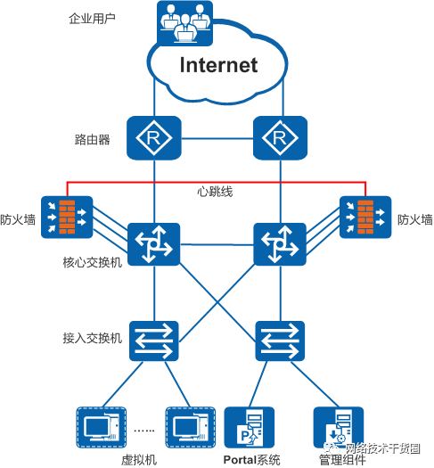
防火墙在云计算网络中的应用示意图
在云计算网络中,主要用到了防火墙的如下功能:
双机热备
两台防火墙之间形成主备备份方式的双机热备状态,提高业务可靠性。
NAT Server
通过NAT Server将虚拟机和Portal系统的公网地址发布出去,供Internet上的企业用户访问。
虚拟系统
为每一个虚拟机划分一个虚拟系统,隔离企业用户访问虚拟机的业务;同时还可以在虚拟系统中配置安全策略,实现访问控制。
方案一:防火墙作为网关典型组网
该云计算网络中,核心交换机使用CE12800、接入交换机使用CE6800、防火墙使用USG9500,本案例重点关注防火墙上的配置,整体的组网环境如图所示。
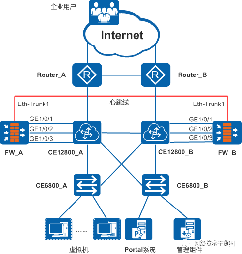
云计算网络组网图
云计算网络中主要有如下几个需求:
不同的外网企业用户访问虚拟机时,相互之间不能影响,业务必须隔离。同时,每个虚拟机业务可使用的带宽资源也要限制在一定范围内,避免占用大量资源。
内部网络中的虚拟机和Portal系统都配置私网地址,要求对外发布两者的公网地址,使外网企业用户能够通过公网地址访问虚拟机和Portal系统。
对外网企业用户访问虚拟机和Portal系统的行为进行控制,仅允许访问业务的流量通过。
提高设备的可靠性,不能因为一台设备出现故障而导致业务中断。
防火墙旁挂在核心交换机CE12800上,使用如下特性来满足上述需求:
使用虚拟系统隔离外网企业用户访问虚拟机的业务,每一个虚拟机都属于一个虚拟系统,每个虚拟系统中都限制了最大带宽资源。
使用子接口与CE12800相连,将子接口划分到虚拟系统和根系统中,虚拟系统中的子接口用来传输虚拟机业务,根系统中的子接口用来传输Portal系统业务。
使用NAT Server对外发布虚拟机和Portal系统的公网地址,在每个虚拟系统中配置针对虚拟机的NAT Server,在根系统中配置针对Portal系统的NAT Server。
使用安全策略对虚拟机和Portal系统的业务进行访问控制,在每个虚拟系统中配置针对虚拟机业务的安全策略,在根系统中配置针对Portal系统业务的安全策略。
使用双机热备提高可靠性,两台防火墙形成主备备份状态的双机热备,当主用防火墙出现故障时,备用防火墙接替其工作,业务不会中断。
业务规划
如图所示,FW旁挂在CE12800上,工作在三层转发模式。CE12800从逻辑上分为上行、下行两个部分,上行部分工作在三层转发(L3)模式,下行部分工作在二层转发(L2)模式。FW与CE12800的上行部分之间运行OSPF,与CE12800的下行部分之间运行VRRP,FW上VRRP的虚拟IP地址作为虚拟机和Portal系统的网关。外网企业用户访问虚拟机和Portal系统的流量经过CE12800的上行部分转发至FW处理后,再经过CE12800的下行部分转发至虚拟机和Portal;回程流量则经过CE12800的下行部分转发至FW处理后,再经过CE12800的上行部分发送出去。
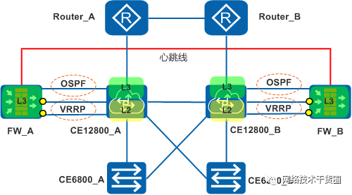
FW旁挂连接示意图
详细的规划情况在下面逐一介绍。
接口和安全区域
下面以FW_A和CE12800_A为例,介绍两者之间的连接情况。
如图所示,FW_A上的GE1/0/1接口与CE12800_A上的10GE1/1/0/1接口相连,详细的连接情况如下:
FW_A上的GE1/0/1接口划分了多个子接口(此处仅以三个子接口为例进行说明),每个子接口上都配置了IP地址。其中多数的子接口都属于不同的虚拟系统,划分到虚拟系统的Untrust区域中;一个子接口属于根系统,划分到根系统的Untrust区域中。
CE12800_A上的10GE1/1/0/1接口为Trunk口,允许多个VLAN的报文通过,在每个Vlanif接口上都配置IP地址,逻辑上与FW_A上相应的子接口连接。
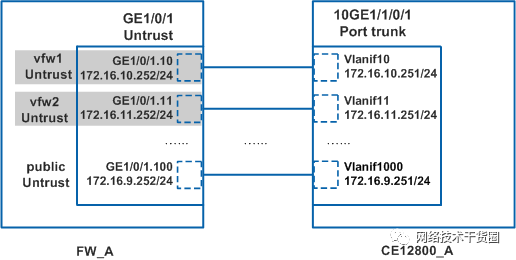
FW_A上的GE1/0/1接口连接示意图
如图所示,FW_A上的GE1/0/2接口与CE12800_A上的10GE1/1/0/2接口相连,详细的连接情况如下:
FW_A上的GE1/0/2接口划分了两个子接口(也可以根据Portal系统的实际网络情况划分多个子接口),每个子接口上都配置了IP地址,每个子接口都划分到根系统的DMZ区域中。
CE12800_A上的10GE1/1/0/2接口为Trunk口,允许多个VLAN的报文通过。
FW_A上子接口的VRRP虚拟IP地址作为Portal系统的网关,终结VLAN,CE12800_A的作用是二层透传报文。
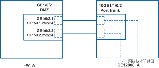
FW_A上的GE1/0/2接口连接示意图
如图所示,FW_A上的GE1/0/3接口与CE12800_A上的10GE1/1/0/3接口相连,详细的连接情况如下:
FW_A上的GE1/0/3接口划分了多个子接口(此处仅以两个子接口为例进行说明),每个子接口上都配置了IP地址。每个子接口都属于不同的虚拟系统,划分到虚拟系统的Trust区域中。
CE12800_A上的10GE1/1/0/3接口为Trunk口,允许多个VLAN的报文通过。
FW_A上子接口的VRRP虚拟IP地址作为虚拟机的网关,终结VLAN,CE12800_A的作用是二层透传报文。
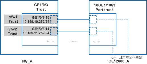
FW_A上的GE1/0/3接口连接示意图
FW_B和CE12800_B之间的连接情况与上面的内容相同,此处不再赘述。
虚拟机之间的互访需求,可以通过访问各自的公网地址,互访报文经过CE12800转发来实现。
配置步骤
前提条件
虚拟系统的License文件已经申请,并在FW_A和FW_B上成功激活。
操作步骤
1.配置接口和安全区域。
在FW_A上创建子接口。
在FW_A上创建子接口。 system-view
[FW_A] interface GigabitEthernet 1/0/1.10
[FW_A-GigabitEthernet1/0/1.10] quit
[FW_A] interface GigabitEthernet 1/0/1.11
[FW_A-GigabitEthernet1/0/1.11] quit
[FW_A] interface GigabitEthernet 1/0/1.1000
[FW_A-GigabitEthernet1/0/1.1000] quit
[FW_A] interface GigabitEthernet 1/0/2.1
[FW_A-GigabitEthernet1/0/2.1] quit
[FW_A] interface GigabitEthernet 1/0/2.2
[FW_A-GigabitEthernet1/0/2.2] quit
[FW_A] interface GigabitEthernet 1/0/3.10
[FW_A-GigabitEthernet1/0/3.10] quit
[FW_A] interface GigabitEthernet 1/0/3.11
[FW_A-GigabitEthernet1/0/3.11] quit
在FW_B上创建子接口。
 system-view
[FW_B] interface GigabitEthernet 1/0/1.10
[FW_B-GigabitEthernet1/0/1.10] quit
[FW_B] interface GigabitEthernet 1/0/1.11
[FW_B-GigabitEthernet1/0/1.11] quit
[FW_B] interface GigabitEthernet 1/0/1.1000
[FW_B-GigabitEthernet1/0/1.1000] quit
[FW_B] interface GigabitEthernet 1/0/2.1
[FW_B-GigabitEthernet1/0/2.1] quit
[FW_B] interface GigabitEthernet 1/0/2.2
[FW_B-GigabitEthernet1/0/2.2] quit
[FW_B] interface GigabitEthernet 1/0/3.10
[FW_B-GigabitEthernet1/0/3.10] quit
[FW_B] interface GigabitEthernet 1/0/3.11
[FW_B-GigabitEthernet1/0/3.11] quit
在FW_A上配置Eth-Trunk接口。
[FW_A] interface Eth-Trunk 1
[FW_A-Eth-Trunk1] ip address 10.1.1.1 30
[FW_A-Eth-Trunk1] quit
[FW_A] interface GigabitEthernet 2/0/1
[FW_A-GigabitEthernet2/0/1] eth-trunk 1
[FW_A-GigabitEthernet2/0/1] quit
[FW_A] interface GigabitEthernet 2/0/2
[FW_A-GigabitEthernet2/0/2] eth-trunk 1
[FW_A-GigabitEthernet2/0/2] quit
在FW_B上配置Eth-Trunk接口。
[FW_B] interface Eth-Trunk 1
[FW_B-Eth-Trunk1] ip address 10.1.1.2 30
[FW_B-Eth-Trunk1] quit
[FW_B] interface GigabitEthernet 2/0/1
[FW_B-GigabitEthernet2/0/1] eth-trunk 1
[FW_B-GigabitEthernet2/0/1] quit
[FW_B] interface GigabitEthernet 2/0/2
[FW_B-GigabitEthernet2/0/2] eth-trunk 1
[FW_B-GigabitEthernet2/0/2] quit
在FW_A上为根系统接口配置IP地址,并将接口加入根系统的安全区域。
[FW_A] interface GigabitEthernet 1/0/1.1000
[FW_A-GigabitEthernet1/0/1.1000] ip address 172.16.9.252 24
[FW_A-GigabitEthernet1/0/1.1000] quit
[FW_A] interface GigabitEthernet 1/0/2.1
[FW_A-GigabitEthernet1/0/2.1] ip address 10.159.1.252 24
[FW_A-GigabitEthernet1/0/2.1] quit
[FW_A] interface GigabitEthernet 1/0/2.2
[FW_A-GigabitEthernet1/0/2.2] ip address 10.159.2.252 24
[FW_A-GigabitEthernet1/0/2.2] quit
[FW_A] firewall zone trust
[FW_A-zone-trust] add interface GigabitEthernet 1/0/3
[FW_A-zone-trust] quit
[FW_A] firewall zone untrust
[FW_A-zone-untrust] add interface GigabitEthernet 1/0/1
[FW_A-zone-untrust] add interface GigabitEthernet 1/0/1.1000
[FW_A-zone-untrust] quit
[FW_A] firewall zone dmz
[FW_A-zone-dmz] add interface GigabitEthernet 1/0/2
[FW_A-zone-dmz] add interface GigabitEthernet 1/0/2.1
[FW_A-zone-dmz] add interface GigabitEthernet 1/0/2.2
[FW_A-zone-dmz] quit
[FW_A] firewall zone name hrpzone
[FW_A-zone-hrpzone] set priority 65
[FW_A-zone-hrpzone] add interface Eth-Trunk 1
[FW_A-zone-hrpzone] quit
在FW_B上为根系统接口配置IP地址,并将接口加入根系统的安全区域。
[FW_B] interface GigabitEthernet 1/0/1.1000
[FW_B-GigabitEthernet1/0/1.1000] ip address 172.16.9.253 24
[FW_B-GigabitEthernet1/0/1.1000] quit
[FW_B] interface GigabitEthernet 1/0/2.1
[FW_B-GigabitEthernet1/0/2.1] ip address 10.159.1.253 24
[FW_B-GigabitEthernet1/0/2.1] quit
[FW_B] interface GigabitEthernet 1/0/2.2
[FW_B-GigabitEthernet1/0/2.2] ip address 10.159.2.253 24
[FW_B-GigabitEthernet1/0/2.2] quit
[FW_B] firewall zone trust
[FW_B-zone-trust] add interface GigabitEthernet 1/0/3
[FW_B-zone-trust] quit
[FW_B] firewall zone untrust
[FW_B-zone-untrust] add interface GigabitEthernet 1/0/1
[FW_B-zone-untrust] add interface GigabitEthernet 1/0/1.1000
[FW_B-zone-untrust] quit
[FW_B] firewall zone dmz
[FW_B-zone-dmz] add interface GigabitEthernet 1/0/2
[FW_B-zone-dmz] add interface GigabitEthernet 1/0/2.1
[FW_B-zone-dmz] add interface GigabitEthernet 1/0/2.2
[FW_B-zone-dmz] quit
[FW_B] firewall zone name hrpzone
[FW_B-zone-hrpzone] set priority 65
[FW_B-zone-hrpzone] add interface Eth-Trunk 1
[FW_B-zone-hrpzone] quit
2.配置虚拟系统。
在FW_A上开启虚拟系统功能。
[FW_A] vsys enable
在FW_B上开启虚拟系统功能。
[FW_B] vsys enable
在FW_A上配置资源类。
[FW_A] resource-class vfw1_car
[FW_A-resource-class-vfw1_car] resource-item-limit bandwidth 100 entire
[FW_A-resource-class-vfw1_car] quit
[FW_A] resource-class vfw2_car
[FW_A-resource-class-vfw2_car] resource-item-limit bandwidth 100 entire
[FW_A-resource-class-vfw2_car] quit
在FW_B上配置资源类。
[FW_B] resource-class vfw1_car
[FW_B-resource-class-vfw1_car] resource-item-limit bandwidth 100 entire
[FW_B-resource-class-vfw1_car] quit
[FW_B] resource-class vfw2_car
[FW_B-resource-class-vfw2_car] resource-item-limit bandwidth 100 entire
[FW_B-resource-class-vfw2_car] quit
在FW_A上创建虚拟系统,并为虚拟系统分配资源。
[FW_A] vsys name vfw1
[FW_A-vsys-vfw1] assign resource-class vfw1_car
[FW_A-vsys-vfw1] assign interface GigabitEthernet 1/0/1.10
[FW_A-vsys-vfw1] assign interface GigabitEthernet 1/0/3.10
[FW_A-vsys-vfw1] assign global-ip 118.1.1.1 118.1.1.1 exclusive
[FW_A-vsys-vfw1] quit
[FW_A] vsys name vfw2
[FW_A-vsys-vfw2] assign resource-class vfw2_car
[FW_A-vsys-vfw2] assign interface GigabitEthernet 1/0/1.11
[FW_A-vsys-vfw2] assign interface GigabitEthernet 1/0/3.11
[FW_A-vsys-vfw2] assign global-ip 118.1.1.2 118.1.1.2 exclusive
[FW_A-vsys-vfw2] quit
在FW_B上创建虚拟系统,并为虚拟系统分配资源。
[FW_B] vsys name vfw1
[FW_B-vsys-vfw1] assign resource-class vfw1_car
[FW_B-vsys-vfw1] assign interface GigabitEthernet 1/0/1.10
[FW_B-vsys-vfw1] assign interface GigabitEthernet 1/0/3.10
[FW_B-vsys-vfw1] assign global-ip 118.1.1.1 118.1.1.1 exclusive
[FW_B-vsys-vfw1] quit
[FW_B] vsys name vfw2
[FW_B-vsys-vfw2] assign resource-class vfw2_car
[FW_B-vsys-vfw2] assign interface GigabitEthernet 1/0/1.11
[FW_B-vsys-vfw2] assign interface GigabitEthernet 1/0/3.11
[FW_B-vsys-vfw2] assign global-ip 118.1.1.2 118.1.1.2 exclusive
[FW_B-vsys-vfw2] quit
在FW_A上的虚拟系统vfw1中配置接口的IP地址,并将接口加入安全区域。
[FW_A] switch vsys vfw1
 system-view
[FW_A-vfw1] interface GigabitEthernet 1/0/1.10
[FW_A-vfw1-GigabitEthernet1/0/1.10] ip address 172.16.10.252 24
[FW_A-vfw1-GigabitEthernet1/0/1.10] quit
[FW_A-vfw1] interface GigabitEthernet 1/0/3.10
[FW_A-vfw1-GigabitEthernet1/0/3.10] ip address 10.159.10.252 24
[FW_A-vfw1-GigabitEthernet1/0/3.10] quit
[FW_A-vfw1] firewall zone untrust
[FW_A-vfw1-zone-untrust] add interface GigabitEthernet 1/0/1.10
[FW_A-vfw1-zone-untrust] quit
[FW_A-vfw1] firewall zone trust
[FW_A-vfw1-zone-trust] add interface GigabitEthernet 1/0/3.10
[FW_A-vfw1-zone-trust] quit
[FW_A-vfw1] quit
 quit
参考上述步骤,在FW_A上的虚拟系统vfw2中配置接口的IP地址,并将接口加入安全区域。
在FW_B上的虚拟系统vfw1中配置接口的IP地址,并将接口加入安全区域。
[FW_B] switch vsys vfw1
 system-view
[FW_B-vfw1] interface GigabitEthernet 1/0/1.10
[FW_B-vfw1-GigabitEthernet1/0/1.10] ip address 172.16.10.253 24
[FW_B-vfw1-GigabitEthernet1/0/1.10] quit
[FW_B-vfw1] interface GigabitEthernet 1/0/3.10
[FW_B-vfw1-GigabitEthernet1/0/3.10] ip address 10.159.10.253 24
[FW_B-vfw1-GigabitEthernet1/0/3.10] quit
[FW_B-vfw1] firewall zone untrust
[FW_B-vfw1-zone-untrust] add interface GigabitEthernet 1/0/1.10
[FW_B-vfw1-zone-untrust] quit
[FW_B-vfw1] firewall zone trust
[FW_B-vfw1-zone-trust] add interface GigabitEthernet 1/0/3.10
[FW_B-vfw1-zone-trust] quit
[FW_B-vfw1] quit
 quit
参考上述步骤,在FW_B上的虚拟系统vfw2中配置接口的IP地址,并将接口加入安全区域。
3.配置路由。
在FW_A上配置根系统的路由。
[FW_A] ip route-static 0.0.0.0 0.0.0.0 172.16.9.251
[FW_A] ip route-static 117.1.1.1 32 NULL 0
[FW_A] ip route-static 117.1.1.2 32 NULL 0
[FW_A] ospf 1000
[FW_A-ospf-1000] import-route static
[FW_A-ospf-1000] area 0
[FW_A-ospf-1000-area-0.0.0.0] network 172.16.9.0 0.0.0.255
[FW_A-ospf-1000-area-0.0.0.0] quit
[FW_A-ospf-1000] quit
在FW_B上配置根系统的路由。
[FW_B] ip route-static 0.0.0.0 0.0.0.0 172.16.9.251
[FW_B] ip route-static 117.1.1.1 32 NULL 0
[FW_B] ip route-static 117.1.1.2 32 NULL 0
[FW_B] ospf 1000
[FW_B-ospf-1000] import-route static
[FW_B-ospf-1000] area 0
[FW_B-ospf-1000-area-0.0.0.0] network 172.16.9.0 0.0.0.255
[FW_B-ospf-1000-area-0.0.0.0] quit
[FW_B-ospf-1000] quit
在FW_A上配置虚拟系统的路由。
[FW_A] ip vpn-instance vfw1
[FW_A-vpn-instance-vfw1] route-distinguisher 10:1
[FW_A-vpn-instance-vfw1] quit
[FW_A] ip vpn-instance vfw2
[FW_A-vpn-instance-vfw2] route-distinguisher 11:1
[FW_A-vpn-instance-vfw2] quit
[FW_A] ospf 1 vpn-instance vfw1
[FW_A-ospf-1] import-route static
[FW_A-ospf-1] area 0
[FW_A-ospf-1-area-0.0.0.0] network 172.16.10.0 0.0.0.255
[FW_A-ospf-1-area-0.0.0.0] quit
[FW_A-ospf-1] quit
[FW_A] ospf 2 vpn-instance vfw2
[FW_A-ospf-2] import-route static
[FW_A-ospf-2] area 0
[FW_A-ospf-2-area-0.0.0.0] network 172.16.11.0 0.0.0.255
[FW_A-ospf-2-area-0.0.0.0] quit
[FW_A-ospf-2] quit
[FW_A] switch vsys vfw1
 system-view
[FW_A-vfw1] ip route-static 0.0.0.0 0.0.0.0 172.16.10.251
[FW_A-vfw1] ip route-static 118.1.1.1 32 NULL 0
[FW_A-vfw1] quit
 quit
[FW_A] switch vsys vfw2
 system-view
[FW_A-vfw2] ip route-static 0.0.0.0 0.0.0.0 172.16.11.251
[FW_A-vfw2] ip route-static 118.1.1.2 32 NULL 0
[FW_A-vfw2] quit
 quit
在FW_B上配置虚拟系统的路由。
[FW_B] ip vpn-instance vfw1
[FW_B-vpn-instance-vfw1] route-distinguisher 10:1
[FW_B-vpn-instance-vfw1] quit
[FW_B] ip vpn-instance vfw2
[FW_B-vpn-instance-vfw2] route-distinguisher 11:1
[FW_B-vpn-instance-vfw2] quit
[FW_B] ospf 1 vpn-instance vfw1
[FW_B-ospf-1] import-route static
[FW_B-ospf-1] area 0
[FW_B-ospf-1-area-0.0.0.0] network 172.16.10.0 0.0.0.255
[FW_B-ospf-1-area-0.0.0.0] quit
[FW_B-ospf-1] quit
[FW_B] ospf 2 vpn-instance vfw2
[FW_B-ospf-2] import-route static
[FW_B-ospf-2] area 0
[FW_B-ospf-2-area-0.0.0.0] network 172.16.11.0 0.0.0.255
[FW_B-ospf-2-area-0.0.0.0] quit
[FW_B-ospf-2] quit
[FW_B] switch vsys vfw1
 system-view
[FW_B-vfw1] ip route-static 0.0.0.0 0.0.0.0 172.16.10.251
[FW_B-vfw1] ip route-static 118.1.1.1 32 NULL 0
[FW_B-vfw1] quit
 quit
[FW_B] switch vsys vfw2
 system-view
[FW_B-vfw2] ip route-static 0.0.0.0 0.0.0.0 172.16.11.251
[FW_B-vfw2] ip route-static 118.1.1.2 32 NULL 0
[FW_B-vfw2] quit
 quit
4.配置双机热备。
在FW_A上配置VGMP组监控上行GE1/0/1接口。
[FW_A] hrp track interface GigabitEthernet 1/0/1
在FW_A上配置根据VGMP状态调整OSPF Cost值功能。
[FW_A] hrp adjust ospf-cost enable
在FW_A上配置VRRP备份组,并将其状态设置为Active。
[FW_A] interface GigabitEthernet 1/0/3.10
[FW_A-GigabitEthernet1/0/3.10] vlan-type dot1q 10
[FW_A-GigabitEthernet1/0/3.10] vrrp vrid 10 virtual-ip 10.159.10.254 active
[FW_A-GigabitEthernet1/0/3.10] quit
[FW_A] interface GigabitEthernet 1/0/3.11
[FW_A-GigabitEthernet1/0/3.11] vlan-type dot1q 11
[FW_A-GigabitEthernet1/0/3.11] vrrp vrid 11 virtual-ip 10.159.11.254 active
[FW_A-GigabitEthernet1/0/3.11] quit
[FW_A] interface GigabitEthernet 1/0/2.1
[FW_A-GigabitEthernet1/0/2.1] vlan-type dot1q 1
[FW_A-GigabitEthernet1/0/2.1] vrrp vrid 1 virtual-ip 10.159.1.254 active
[FW_A-GigabitEthernet1/0/2.1] quit
[FW_A] interface GigabitEthernet 1/0/2.2
[FW_A-GigabitEthernet1/0/2.2] vlan-type dot1q 2
[FW_A-GigabitEthernet1/0/2.2] vrrp vrid 2 virtual-ip 10.159.2.254 active
[FW_A-GigabitEthernet1/0/2.2] quit
在FW_A上指定心跳口并启用双机热备功能。
[FW_A] hrp interface Eth-Trunk 1 remote 10.1.1.2
[FW_A] hrp enable
在FW_B上配置VGMP组监控上行GE1/0/1接口。
[FW_B] hrp track interface GigabitEthernet 1/0/1
在FW_B上配置根据VGMP状态调整OSPF Cost值功能。
[FW_B] hrp adjust ospf-cost enable
在FW_B上配置VRRP备份组,并将其状态设置为Standby。
[FW_B] interface GigabitEthernet 1/0/3.10
[FW_B-GigabitEthernet1/0/3.10] vlan-type dot1q 10
[FW_B-GigabitEthernet1/0/3.10] vrrp vrid 10 virtual-ip 10.159.10.254 standby
[FW_B-GigabitEthernet1/0/3.10] quit
[FW_B] interface GigabitEthernet 1/0/3.11
[FW_B-GigabitEthernet1/0/3.11] vlan-type dot1q 11
[FW_B-GigabitEthernet1/0/3.11] vrrp vrid 11 virtual-ip 10.159.11.254 standby
[FW_B-GigabitEthernet1/0/3.11] quit
[FW_B] interface GigabitEthernet 1/0/2.1
[FW_B-GigabitEthernet1/0/2.1] vlan-type dot1q 1
[FW_B-GigabitEthernet1/0/2.1] vrrp vrid 1 virtual-ip 10.159.1.254 standby
[FW_B-GigabitEthernet1/0/2.1] quit
[FW_B] interface GigabitEthernet 1/0/2.2
[FW_B-GigabitEthernet1/0/2.2] vlan-type dot1q 2
[FW_B-GigabitEthernet1/0/2.2] vrrp vrid 2 virtual-ip 10.159.2.254 standby
[FW_B-GigabitEthernet1/0/2.2] quit
在FW_B上指定心跳口并启用双机热备功能。
[FW_B] hrp interface Eth-Trunk 1 remote 10.1.1.1
[FW_B] hrp enable
5.配置安全策略。
在FW_A上的根系统中配置安全策略。
HRP_M[FW_A] security-policy
HRP_M[FW_A-policy-security] rule name sec_portal
HRP_M[FW_A-policy-security-rule-sec_portal] source-zone untrust
HRP_M[FW_A-policy-security-rule-sec_portal] destination-zone dmz
HRP_M[FW_A-policy-security-rule-sec_portal] destination-address 10.159.0.0 16
HRP_M[FW_A-policy-security-rule-sec_portal] action permit
HRP_M[FW_A-policy-security-rule-sec_portal] profile av default
HRP_M[FW_A-policy-security-rule-sec_portal] profile ips default
HRP_M[FW_A-policy-security-rule-sec_portal] quit
HRP_M[FW_A-policy-security] rule name sec_ospf
HRP_M[FW_A-policy-security-rule-sec_ospf] source-zone untrust local
HRP_M[FW_A-policy-security-rule-sec_ospf] destination-zone local untrust
HRP_M[FW_A-policy-security-rule-sec_ospf] service ospf
HRP_M[FW_A-policy-security-rule-sec_ospf] action permit
HRP_M[FW_A-policy-security-rule-sec_ospf] quit
HRP_M[FW_A-policy-security] quit
在FW_A上的虚拟系统vfw1中配置安全策略。
HRP_M[FW_A] switch vsys vfw1
HRP_M system-view
HRP_M[FW_A-vfw1] security-policy
HRP_M[FW_A-vfw1-policy-security] rule name sec_vm1
HRP_M[FW_A-vfw1-policy-security-rule-sec_vm1] source-zone untrust
HRP_M[FW_A-vfw1-policy-security-rule-sec_vm1] destination-zone trust
HRP_M[FW_A-vfw1-policy-security-rule-sec_vm1] destination-address 10.159.10.0 24
HRP_M[FW_A-vfw1-policy-security-rule-sec_vm1] profile av default
HRP_M[FW_A-vfw1-policy-security-rule-sec_vm1] profile ips default
HRP_M[FW_A-vfw1-policy-security-rule-sec_vm1] action permit
HRP_M[FW_A-vfw1-policy-security-rule-sec_vm1] quit
HRP_M[FW_A-vfw1-policy-security] rule name sec_vm1_ospf
HRP_M[FW_A-vfw1-policy-security-rule-sec_vm1_ospf] source-zone untrust local
HRP_M[FW_A-vfw1-policy-security-rule-sec_vm1_ospf] destination-zone local untrust
HRP_M[FW_A-vfw1-policy-security-rule-sec_vm1_ospf] service ospf
HRP_M[FW_A-vfw1-policy-security-rule-sec_vm1_ospf] action permit
HRP_M[FW_A-vfw1-policy-security-rule-sec_vm1_ospf] quit
HRP_M[FW_A-vfw1-policy-security] quit
HRP_M[FW_A-vfw1] quit
HRP_M quit
参考上述步骤,在FW_A上的虚拟系统vfw2中配置安全策略。
双机热备状态形成后,FW_A上的配置会自动同步到FW_B上,因此无需在FW_B上手动配置安全策略。
6.配置策略备份加速。
当策略数量较多时(比如超过100条),为了提升策略加速期间的匹配效率,需要开启备份加速功能。但是开启该功能后,新配置的策略需要等待策略备份加速完成后才能生效。
HRP_M[FW-A] policy accelerate standby enable
双机热备状态形成后,FW_A上的配置会自动同步到FW_B上,因此无需在FW_B上手动配置策略备份加速。
7.配置NAT Server。
说明:
此处给出的NAT Server配置命令仅作为示例,实际网络环境中会在管理组件上配置NAT Server,管理组件将配置数据下发给FW。
在FW_A上的根系统中配置NAT Server。
HRP_M[FW_A] nat server nat_server_portal1 global 117.1.1.1 inside 10.159.1.100
HRP_M[FW_A] nat server nat_server_portal2 global 117.1.1.2 inside 10.159.2.100
在FW_A上的虚拟系统vfw1中配置NAT Server。
HRP_M[FW_A] switch vsys vfw1
HRP_M system-view
HRP_M[FW_A-vfw1] nat server nat_server_vm1 global 118.1.1.1 inside 10.159.10.100
HRP_M[FW_A-vfw1] quit
HRP_M quit
参考上述步骤,在FW_A上的虚拟系统vfw2中配置NAT Server。
双机热备状态形成后,FW_A上的配置会自动同步到FW_B上,因此无需在FW_B上手动配置NAT Server。
8.配置其它网络设备。
案例中重点介绍FW上的配置,其它网络设备上的配置请关注以下几个配置项:
上行路由器上要配置去往虚拟机和Portal系统的Global地址的路由,下一跳为CE12800。
在CE12800上配置OSPF时,在OSPF进程中要配置default-route-advertise always命令。
CE6800二层透传报文,配置二层转发即可。
结果验证
在FW_A和FW_B上使用display hrp state命令查看当前HRP的状态,可以看到HRP状态正常。
Internet上的企业用户可以正常访问虚拟机业务。
Internet上的企业用户可以正常访问Portal系统。
FW_A的GE1/0/2.1接口上执行shutdown命令,模拟链路故障,发现主备正常倒换,业务不会中断。
方案二:交换机作为网关典型组网
该云计算网络中,核心交换机使用CE12800、接入交换机使用CE6800、防火墙使用USG9500,本案例重点关注防火墙上的配置,整体的组网环境如图所示。

云计算网络组网图
云计算网络中主要有如下几个需求:
不同的外网企业用户访问虚拟机时,相互之间不能影响,业务必须隔离。同时,每个虚拟机业务可使用的带宽资源也要限制在一定范围内,避免占用大量资源。
内部网络中的虚拟机和Portal系统都配置私网地址,要求对外发布两者的公网地址,使外网企业用户能够通过公网地址访问虚拟机和Portal系统。
对外网企业用户访问虚拟机和Portal系统的行为进行控制,仅允许访问业务的流量通过。
提高设备的可靠性,不能因为一台设备出现故障而导致业务中断。
防火墙旁挂在核心交换机CE12800上,使用如下特性来满足上述需求:
使用虚拟系统隔离外网企业用户访问虚拟机的业务,每一个虚拟机都属于一个虚拟系统,每个虚拟系统中都限制了最大带宽资源。
使用子接口与CE12800相连,将子接口划分到虚拟系统和根系统中,虚拟系统中的子接口用来传输虚拟机业务,根系统中的子接口用来传输Portal系统业务。
使用NAT Server对外发布虚拟机和Portal系统的公网地址,在每个虚拟系统中配置针对虚拟机的NAT Server,在根系统中配置针对Portal系统的NAT Server。
使用安全策略对虚拟机和Portal系统的业务进行访问控制,在每个虚拟系统中配置针对虚拟机业务的安全策略,在根系统中配置针对Portal系统业务的安全策略。
使用双机热备提高可靠性,两台防火墙形成主备备份状态的双机热备,当主用防火墙出现故障时,备用防火墙接替其工作,业务不会中断。
业务规划
如图所示,FW旁挂在CE12800上,工作在三层转发模式。CE12800上配置VRF功能,虚拟成连接上行的交换机(根交换机Public)和连接下行的交换机(多个虚拟交换机VRF)。FW与CE12800的根交换机Public和虚拟交换机VRF之间都运行VRRP,CE12800上VRRP的虚拟IP地址作为虚拟机和Portal系统的网关。外网企业用户访问虚拟机和Portal系统的流量经过CE12800的根交换机Public转发至FW处理后,再经过CE12800的虚拟交换机VRF转发至虚拟机和Portal;回程流量则经过CE12800的虚拟交换机VRF转发至FW处理后,再经过CE12800的根交换机Public发送出去。

FW旁挂连接示意图
详细的规划情况在下面逐一介绍。
接口和安全区域
下面以FW_A和CE12800_A为例,介绍两者之间的连接情况。
如图所示,FW_A上的GE1/0/1接口与CE12800_A上的10GE1/1/0/1接口相连,详细的连接情况如下:
FW_A上的GE1/0/1接口划分了多个子接口(此处仅以三个子接口为例进行说明),每个子接口上都配置了IP地址。其中多数的子接口都属于不同的虚拟系统,划分到虚拟系统的Untrust区域中;一个子接口属于根系统,划分到根系统的Untrust区域中。
CE12800_A上的10GE1/1/0/1接口为Trunk口,允许多个VLAN的报文通过,在每个Vlanif接口上都配置IP地址,逻辑上与FW_A上相应的子接口连接。
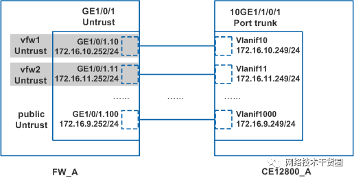
FW_A上的GE1/0/1接口连接示意图
如图所示,FW_A上的GE1/0/2接口与CE12800_A上的10GE1/1/0/2接口相连,详细的连接情况如下:
FW_A上的GE1/0/2接口划分了两个子接口(也可以根据Portal系统的实际网络情况划分多个子接口),每个子接口上都配置了IP地址,每个子接口都划分到根系统的DMZ区域中。
CE12800_A上的10GE1/1/0/2接口为Trunk口,允许两个VLAN的报文通过,在每个Vlanif接口上都配置IP地址,逻辑上与FW_A上相应的子接口连接。
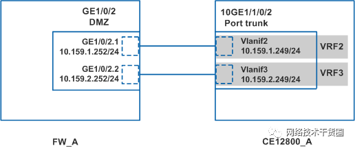
FW_A上的GE1/0/2接口连接示意图
如图所示,FW_A上的GE1/0/3接口与CE12800_A上的10GE1/1/0/3接口相连,详细的连接情况如下:
FW_A上的GE1/0/3接口划分了多个子接口(此处仅以两个子接口为例进行说明),每个子接口上都配置了IP地址。每个子接口都属于不同的虚拟系统,划分到虚拟系统的Trust区域中。
CE12800_A上的10GE1/1/0/3接口为Trunk口,允许多个VLAN的报文通过,在每个Vlanif接口上都配置IP地址,逻辑上与FW_A上相应的子接口连接。
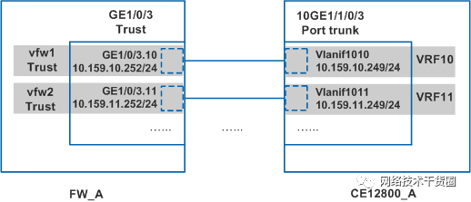
FW_A上的GE1/0/3接口连接示意图
FW_B和CE12800_B之间的连接情况与上面的内容相同,只是IP地址有所区别,此处不再赘述。
虚拟机之间的互访需求,可以通过访问各自的公网地址,互访报文经过CE12800转发来实现。
配置步骤
前提条件
虚拟系统的License文件已经申请,并在FW_A和FW_B上成功激活。
操作步骤
1.配置接口和安全区域。
在FW_A上创建子接口。
 system-view
[FW_A] interface GigabitEthernet 1/0/1.10
[FW_A-GigabitEthernet1/0/1.10] quit
[FW_A] interface GigabitEthernet 1/0/1.11
[FW_A-GigabitEthernet1/0/1.11] quit
[FW_A] interface GigabitEthernet 1/0/1.1000
[FW_A-GigabitEthernet1/0/1.1000] quit
[FW_A] interface GigabitEthernet 1/0/2.1
[FW_A-GigabitEthernet1/0/2.1] quit
[FW_A] interface GigabitEthernet 1/0/2.2
[FW_A-GigabitEthernet1/0/2.2] quit
[FW_A] interface GigabitEthernet 1/0/3.10
[FW_A-GigabitEthernet1/0/3.10] quit
[FW_A] interface GigabitEthernet 1/0/3.11
[FW_A-GigabitEthernet1/0/3.11] quit
在FW_B上创建子接口。
 system-view
[FW_B] interface GigabitEthernet 1/0/1.10
[FW_B-GigabitEthernet1/0/1.10] quit
[FW_B] interface GigabitEthernet 1/0/1.11
[FW_B-GigabitEthernet1/0/1.11] quit
[FW_B] interface GigabitEthernet 1/0/1.1000
[FW_B-GigabitEthernet1/0/1.1000] quit
[FW_B] interface GigabitEthernet 1/0/2.1
[FW_B-GigabitEthernet1/0/2.1] quit
[FW_B] interface GigabitEthernet 1/0/2.2
[FW_B-GigabitEthernet1/0/2.2] quit
[FW_B] interface GigabitEthernet 1/0/3.10
[FW_B-GigabitEthernet1/0/3.10] quit
[FW_B] interface GigabitEthernet 1/0/3.11
[FW_B-GigabitEthernet1/0/3.11] quit
在FW_A上配置Eth-Trunk接口。
[FW_A] interface Eth-Trunk 1
[FW_A-Eth-Trunk1] ip address 10.1.1.1 30
[FW_A-Eth-Trunk1] quit
[FW_A] interface GigabitEthernet 2/0/1
[FW_A-GigabitEthernet2/0/1] eth-trunk 1
[FW_A-GigabitEthernet2/0/1] quit
[FW_A] interface GigabitEthernet 2/0/2
[FW_A-GigabitEthernet2/0/2] eth-trunk 1
[FW_A-GigabitEthernet2/0/2] quit
在FW_B上配置Eth-Trunk接口。
[FW_B] interface Eth-Trunk 1
[FW_B-Eth-Trunk1] ip address 10.1.1.2 30
[FW_B-Eth-Trunk1] quit
[FW_B] interface GigabitEthernet 2/0/1
[FW_B-GigabitEthernet2/0/1] eth-trunk 1
[FW_B-GigabitEthernet2/0/1] quit
[FW_B] interface GigabitEthernet 2/0/2
[FW_B-GigabitEthernet2/0/2] eth-trunk 1
[FW_B-GigabitEthernet2/0/2] quit
在FW_A上为根系统接口配置IP地址,并将接口加入根系统的安全区域。
[FW_A] interface GigabitEthernet 1/0/1.1000
[FW_A-GigabitEthernet1/0/1.1000] ip address 172.16.9.252 24
[FW_A-GigabitEthernet1/0/1.1000] quit
[FW_A] interface GigabitEthernet 1/0/2.1
[FW_A-GigabitEthernet1/0/2.1] ip address 10.159.1.252 24
[FW_A-GigabitEthernet1/0/2.1] quit
[FW_A] interface GigabitEthernet 1/0/2.2
[FW_A-GigabitEthernet1/0/2.2] ip address 10.159.2.252 24
[FW_A-GigabitEthernet1/0/2.2] quit
[FW_A] firewall zone trust
[FW_A-zone-trust] add interface GigabitEthernet 1/0/3
[FW_A-zone-trust] quit
[FW_A] firewall zone untrust
[FW_A-zone-untrust] add interface GigabitEthernet 1/0/1
[FW_A-zone-untrust] add interface GigabitEthernet 1/0/1.1000
[FW_A-zone-untrust] quit
[FW_A] firewall zone dmz
[FW_A-zone-dmz] add interface GigabitEthernet 1/0/2
[FW_A-zone-dmz] add interface GigabitEthernet 1/0/2.1
[FW_A-zone-dmz] add interface GigabitEthernet 1/0/2.2
[FW_A-zone-dmz] quit
[FW_A] firewall zone name hrpzone
[FW_A-zone-hrpzone] set priority 65
[FW_A-zone-hrpzone] add interface Eth-Trunk 1
[FW_A-zone-hrpzone] quit
在FW_B上为根系统接口配置IP地址,并将接口加入根系统的安全区域。
[FW_B] interface GigabitEthernet 1/0/1.1000
[FW_B-GigabitEthernet1/0/1.1000] ip address 172.16.9.253 24
[FW_B-GigabitEthernet1/0/1.1000] quit
[FW_B] interface GigabitEthernet 1/0/2.1
[FW_B-GigabitEthernet1/0/2.1] ip address 10.159.1.253 24
[FW_B-GigabitEthernet1/0/2.1] quit
[FW_B] interface GigabitEthernet 1/0/2.2
[FW_B-GigabitEthernet1/0/2.2] ip address 10.159.2.253 24
[FW_B-GigabitEthernet1/0/2.2] quit
[FW_B] firewall zone trust
[FW_B-zone-trust] add interface GigabitEthernet 1/0/3
[FW_B-zone-trust] quit
[FW_B] firewall zone untrust
[FW_B-zone-untrust] add interface GigabitEthernet 1/0/1
[FW_B-zone-untrust] add interface GigabitEthernet 1/0/1.1000
[FW_B-zone-untrust] quit
[FW_B] firewall zone dmz
[FW_B-zone-dmz] add interface GigabitEthernet 1/0/2
[FW_B-zone-dmz] add interface GigabitEthernet 1/0/2.1
[FW_B-zone-dmz] add interface GigabitEthernet 1/0/2.2
[FW_B-zone-dmz] quit
[FW_B] firewall zone name hrpzone
[FW_B-zone-hrpzone] set priority 65
[FW_B-zone-hrpzone] add interface Eth-Trunk 1
[FW_B-zone-hrpzone] quit
2.配置虚拟系统。
在FW_A上开启虚拟系统功能。
[FW_A] vsys enable
在FW_B上开启虚拟系统功能。
[FW_B] vsys enable
在FW_A上配置资源类。
[FW_A] resource-class vfw1_car
[FW_A-resource-class-vfw1_car] resource-item-limit bandwidth 100 entire
[FW_A-resource-class-vfw1_car] quit
[FW_A] resource-class vfw2_car
[FW_A-resource-class-vfw2_car] resource-item-limit bandwidth 100 entire
[FW_A-resource-class-vfw2_car] quit
在FW_B上配置资源类。
[FW_B] resource-class vfw1_car
[FW_B-resource-class-vfw1_car] resource-item-limit bandwidth 100 entire
[FW_B-resource-class-vfw1_car] quit
[FW_B] resource-class vfw2_car
[FW_B-resource-class-vfw2_car] resource-item-limit bandwidth 100 entire
[FW_B-resource-class-vfw2_car] quit
在FW_A上创建虚拟系统,并为虚拟系统分配资源。
[FW_A] vsys name vfw1
[FW_A-vsys-vfw1] assign resource-class vfw1_car
[FW_A-vsys-vfw1] assign interface GigabitEthernet 1/0/1.10
[FW_A-vsys-vfw1] assign interface GigabitEthernet 1/0/3.10
[FW_A-vsys-vfw1] assign global-ip 118.1.1.1 118.1.1.1 exclusive
[FW_A-vsys-vfw1] quit
[FW_A] vsys name vfw2
[FW_A-vsys-vfw2] assign resource-class vfw2_car
[FW_A-vsys-vfw2] assign interface GigabitEthernet 1/0/1.11
[FW_A-vsys-vfw2] assign interface GigabitEthernet 1/0/3.11
[FW_A-vsys-vfw2] assign global-ip 118.1.1.2 118.1.1.2 exclusive
[FW_A-vsys-vfw2] quit
在FW_B上创建虚拟系统,并为虚拟系统分配资源。
[FW_B] vsys name vfw1
[FW_B-vsys-vfw1] assign resource-class vfw1_car
[FW_B-vsys-vfw1] assign interface GigabitEthernet 1/0/1.10
[FW_B-vsys-vfw1] assign interface GigabitEthernet 1/0/3.10
[FW_B-vsys-vfw1] assign global-ip 118.1.1.1 118.1.1.1 exclusive
[FW_B-vsys-vfw1] quit
[FW_B] vsys name vfw2
[FW_B-vsys-vfw2] assign resource-class vfw2_car
[FW_B-vsys-vfw2] assign interface GigabitEthernet 1/0/1.11
[FW_B-vsys-vfw2] assign interface GigabitEthernet 1/0/3.11
[FW_B-vsys-vfw2] assign global-ip 118.1.1.2 118.1.1.2 exclusive
[FW_B-vsys-vfw2] quit
在FW_A上的虚拟系统vfw1中配置接口的IP地址,并将接口加入安全区域。
[FW_A] switch vsys vfw1
 system-view
[FW_A-vfw1] interface GigabitEthernet 1/0/1.10
[FW_A-vfw1-GigabitEthernet1/0/1.10] ip address 172.16.10.252 24
[FW_A-vfw1-GigabitEthernet1/0/1.10] quit
[FW_A-vfw1] interface GigabitEthernet 1/0/3.10
[FW_A-vfw1-GigabitEthernet1/0/3.10] ip address 10.159.10.252 24
[FW_A-vfw1-GigabitEthernet1/0/3.10] quit
[FW_A-vfw1] firewall zone untrust
[FW_A-vfw1-zone-untrust] add interface GigabitEthernet 1/0/1.10
[FW_A-vfw1-zone-untrust] quit
[FW_A-vfw1] firewall zone trust
[FW_A-vfw1-zone-trust] add interface GigabitEthernet 1/0/3.10
[FW_A-vfw1-zone-trust] quit
[FW_A-vfw1] quit
 quit
参考上述步骤,在FW_A上的虚拟系统vfw2中配置接口的IP地址,并将接口加入安全区域。
在FW_B上的虚拟系统vfw1中配置接口的IP地址,并将接口加入安全区域。
[FW_B] switch vsys vfw1
 system-view
[FW_B-vfw1] interface GigabitEthernet 1/0/1.10
[FW_B-vfw1-GigabitEthernet1/0/1.10] ip address 172.16.10.253 24
[FW_B-vfw1-GigabitEthernet1/0/1.10] quit
[FW_B-vfw1] interface GigabitEthernet 1/0/3.10
[FW_B-vfw1-GigabitEthernet1/0/3.10] ip address 10.159.10.253 24
[FW_B-vfw1-GigabitEthernet1/0/3.10] quit
[FW_B-vfw1] firewall zone untrust
[FW_B-vfw1-zone-untrust] add interface GigabitEthernet 1/0/1.10
[FW_B-vfw1-zone-untrust] quit
[FW_B-vfw1] firewall zone trust
[FW_B-vfw1-zone-trust] add interface GigabitEthernet 1/0/3.10
[FW_B-vfw1-zone-trust] quit
[FW_B-vfw1] quit
 quit
参考上述步骤,在FW_B上的虚拟系统vfw2中配置接口的IP地址,并将接口加入安全区域。
3.配置路由。
在FW_A上配置根系统的路由。
[FW_A] ip route-static 0.0.0.0 0.0.0.0 172.16.9.251
[FW_A] ip route-static 117.1.1.1 32 NULL 0
[FW_A] ip route-static 117.1.1.2 32 NULL 0
[FW_A] ip route-static 10.160.1.0 24 10.159.1.251
[FW_A] ip route-static 10.160.2.0 24 10.159.2.251
在FW_B上配置根系统的路由。
[FW_B] ip route-static 0.0.0.0 0.0.0.0 172.16.9.251
[FW_B] ip route-static 117.1.1.1 32 NULL 0
[FW_B] ip route-static 117.1.1.2 32 NULL 0
[FW_B] ip route-static 10.160.1.0 24 10.159.1.251
[FW_B] ip route-static 10.160.2.0 24 10.159.2.251
在FW_A上配置虚拟系统的路由。
[FW_A] switch vsys vfw1
 system-view
[FW_A-vfw1] ip route-static 0.0.0.0 0.0.0.0 172.16.10.251
[FW_A-vfw1] ip route-static 118.1.1.1 32 NULL 0
[FW_A-vfw1] ip route-static 10.160.10.0 24 10.159.10.251
[FW_A-vfw1] quit
 quit
[FW_A] switch vsys vfw2
 system-view
[FW_A-vfw2] ip route-static 0.0.0.0 0.0.0.0 172.16.11.251
[FW_A-vfw2] ip route-static 118.1.1.2 32 NULL 0
[FW_A-vfw2] ip route-static 10.160.11.0 24 10.159.11.251
[FW_A-vfw2] quit
 quit
在FW_B上配置虚拟系统的路由。
[FW_B] switch vsys vfw1
 system-view
[FW_B-vfw1] ip route-static 0.0.0.0 0.0.0.0 172.16.10.251
[FW_B-vfw1] ip route-static 118.1.1.1 32 NULL 0
[FW_B-vfw1] ip route-static 10.160.10.0 24 10.159.10.251
[FW_B-vfw1] quit
 quit
[FW_B] switch vsys vfw2
 system-view
[FW_B-vfw2] ip route-static 0.0.0.0 0.0.0.0 172.16.11.251
[FW_B-vfw2] ip route-static 118.1.1.2 32 NULL 0
[FW_B-vfw2] ip route-static 10.160.11.0 24 10.159.11.251
[FW_B-vfw2] quit
 quit
4.配置双机热备。
在FW_A上配置VRRP备份组,并将其状态设置为Active。
[FW_A] interface GigabitEthernet 1/0/1.10
[FW_A-GigabitEthernet1/0/1.10] vlan-type dot1q 10
[FW_A-GigabitEthernet1/0/1.10] vrrp vrid 10 virtual-ip 172.16.10.254 active
[FW_A-GigabitEthernet1/0/1.10] quit
[FW_A] interface GigabitEthernet 1/0/1.11
[FW_A-GigabitEthernet1/0/1.11] vlan-type dot1q 11
[FW_A-GigabitEthernet1/0/1.11] vrrp vrid 11 virtual-ip 172.16.11.254 active
[FW_A-GigabitEthernet1/0/1.11] quit
[FW_A] interface GigabitEthernet 1/0/1.1000
[FW_A-GigabitEthernet1/0/1.1000] vlan-type dot1q 9
[FW_A-GigabitEthernet1/0/1.1000] vrrp vrid 9 virtual-ip 172.16.9.254 active
[FW_A-GigabitEthernet1/0/1.1000] quit
[FW_A] interface GigabitEthernet 1/0/3.10
[FW_A-GigabitEthernet1/0/3.10] vlan-type dot1q 10
[FW_A-GigabitEthernet1/0/3.10] vrrp vrid 110 virtual-ip 10.159.10.254 active
[FW_A-GigabitEthernet1/0/3.10] quit
[FW_A] interface GigabitEthernet 1/0/3.11
[FW_A-GigabitEthernet1/0/3.11] vlan-type dot1q 11
[FW_A-GigabitEthernet1/0/3.11] vrrp vrid 111 virtual-ip 10.159.11.254 active
[FW_A-GigabitEthernet1/0/3.11] quit
[FW_A] interface GigabitEthernet 1/0/2.1
[FW_A-GigabitEthernet1/0/2.1] vlan-type dot1q 1
[FW_A-GigabitEthernet1/0/2.1] vrrp vrid 1 virtual-ip 10.159.1.254 active
[FW_A-GigabitEthernet1/0/2.1] quit
[FW_A] interface GigabitEthernet 1/0/2.2
[FW_A-GigabitEthernet1/0/2.2] vlan-type dot1q 2
[FW_A-GigabitEthernet1/0/2.2] vrrp vrid 2 virtual-ip 10.159.2.254 active
[FW_A-GigabitEthernet1/0/2.2] quit
在FW_A上指定心跳口并启用双机热备功能。
[FW_A] hrp interface Eth-Trunk 1 remote 10.1.1.2
[FW_A] hrp enable
在FW_B上配置VRRP备份组,并将其状态设置为Standby。
[FW_B] interface GigabitEthernet 1/0/1.10
[FW_B-GigabitEthernet1/0/1.10] vlan-type dot1q 10
[FW_B-GigabitEthernet1/0/1.10] vrrp vrid 10 virtual-ip 172.16.10.254 standby
[FW_B-GigabitEthernet1/0/1.10] quit
[FW_B] interface GigabitEthernet 1/0/1.11
[FW_B-GigabitEthernet1/0/1.11] vlan-type dot1q 11
[FW_B-GigabitEthernet1/0/1.11] vrrp vrid 11 virtual-ip 172.16.11.254 standby
[FW_B-GigabitEthernet1/0/1.11] quit
[FW_B] interface GigabitEthernet 1/0/1.1000
[FW_B-GigabitEthernet1/0/1.1000] vlan-type dot1q 9
[FW_B-GigabitEthernet1/0/1.1000] vrrp vrid 9 virtual-ip 172.16.9.254 standby
[FW_B-GigabitEthernet1/0/1.1000] quit
[FW_B] interface GigabitEthernet 1/0/3.10
[FW_B-GigabitEthernet1/0/3.10] vlan-type dot1q 10
[FW_B-GigabitEthernet1/0/3.10] vrrp vrid 110 virtual-ip 10.159.10.254 standby
[FW_B-GigabitEthernet1/0/3.10] quit
[FW_B] interface GigabitEthernet 1/0/3.11
[FW_B-GigabitEthernet1/0/3.11] vlan-type dot1q 11
[FW_B-GigabitEthernet1/0/3.11] vrrp vrid 111 virtual-ip 10.159.11.254 standby
[FW_B-GigabitEthernet1/0/3.11] quit
[FW_B] interface GigabitEthernet 1/0/2.1
[FW_B-GigabitEthernet1/0/2.1] vlan-type dot1q 1
[FW_B-GigabitEthernet1/0/2.1] vrrp vrid 1 virtual-ip 10.159.1.254 standby
[FW_B-GigabitEthernet1/0/2.1] quit
[FW_B] interface GigabitEthernet 1/0/2.2
[FW_B-GigabitEthernet1/0/2.2] vlan-type dot1q 2
[FW_B-GigabitEthernet1/0/2.2] vrrp vrid 2 virtual-ip 10.159.2.254 standby
[FW_B-GigabitEthernet1/0/2.2] quit
在FW_B上指定心跳口并启用双机热备功能。
[FW_B] hrp interface Eth-Trunk 1 remote 10.1.1.1
[FW_B] hrp enable
5.配置安全策略。
在FW_A上的根系统中配置安全策略。
HRP_M[FW_A] security-policy
HRP_M[FW_A-policy-security] rule name sec_portal
HRP_M[FW_A-policy-security-rule-sec_portal] source-zone untrust
HRP_M[FW_A-policy-security-rule-sec_portal] destination-zone dmz
HRP_M[FW_A-policy-security-rule-sec_portal] destination-address 10.160.0.0 16
HRP_M[FW_A-policy-security-rule-sec_portal] action permit
HRP_M[FW_A-policy-security-rule-sec_portal] profile av default
HRP_M[FW_A-policy-security-rule-sec_portal] profile ips default
HRP_M[FW_A-policy-security-rule-sec_portal] quit
HRP_M[FW_A-policy-security] quit
在FW_A上的虚拟系统vfw1中配置安全策略。
HRP_M[FW_A] switch vsys vfw1
HRP_M system-view
HRP_M[FW_A-vfw1] security-policy
HRP_M[FW_A-vfw1-policy-security] rule name sec_vm1
HRP_M[FW_A-vfw1-policy-security-rule-sec_vm1] source-zone untrust
HRP_M[FW_A-vfw1-policy-security-rule-sec_vm1] destination-zone trust
HRP_M[FW_A-vfw1-policy-security-rule-sec_vm1] destination-address 10.160.10.0 24
HRP_M[FW_A-vfw1-policy-security-rule-sec_vm1] profile av default
HRP_M[FW_A-vfw1-policy-security-rule-sec_vm1] profile ips default
HRP_M[FW_A-vfw1-policy-security-rule-sec_vm1] action permit
HRP_M[FW_A-vfw1-policy-security-rule-sec_vm1] quit
HRP_M[FW_A-vfw1-policy-security] quit
HRP_M[FW_A-vfw1] quit
HRP_M quit
参考上述步骤,在FW_A上的虚拟系统vfw2中配置安全策略。
双机热备状态形成后,FW_A上的配置会自动同步到FW_B上,因此无需在FW_B上手动配置安全策略。
6.配置策略备份加速。
当策略数量较多时(比如超过100条),为了提升策略加速期间的匹配效率,需要开启备份加速功能。但是开启该功能后,新配置的策略需要等待策略备份加速完成后才能生效。HRP_M[FW-A] policy accelerate standby enable
双机热备状态形成后,FW_A上的配置会自动同步到FW_B上,因此无需在FW_B上手动配置策略备份加速。
7.配置NAT Server。
说明:此处给出的NAT Server配置命令仅作为示例,实际网络环境中会在管理组件上配置NAT Server,管理组件将配置数据下发给FW。
在FW_A上的根系统中配置NAT Server。
HRP_M[FW_A] nat server nat_server_portal1 global 117.1.1.1 inside 10.160.1.100
HRP_M[FW_A] nat server nat_server_portal2 global 117.1.1.2 inside 10.160.2.100
在FW_A上的虚拟系统vfw1中配置NAT Server。
HRP_M[FW_A] switch vsys vfw1
HRP_M system-view
HRP_M[FW_A-vfw1] nat server nat_server_vm1 global 118.1.1.1 inside 10.160.10.100
HRP_M[FW_A-vfw1] quit
HRP_M quit
参考上述步骤,在FW_A上的虚拟系统vfw2中配置NAT Server。
双机热备状态形成后,FW_A上的配置会自动同步到FW_B上,因此无需在FW_B上手动配置NAT Server。
8.配置其它网络设备。
本案例中重点介绍FW上的配置,其它网络设备上的配置请关注以下几个配置项:
上行路由器与CE12800之间运行OSPF路由协议,通过OSPF学习到去往虚拟机和Portal系统的公网地址的路由,下一跳为CE12800。
CE12800上配置多个虚拟交换机VRF,并将vlanif与相应的VRF绑定,然后在vlanif上配置VRRP。另外,CE12800上还需要在根交换机Pulic中配置去往虚拟机和Portal系统的公网地址的静态路由,下一跳指向FW上的VRRP虚拟IP地址;在各个虚拟交换机VRF中配置缺省路由,下一跳也指向FW上相应的VRRP虚拟IP地址。
CE6800二层透传报文,配置二层转发即可。
结果验证
在FW_A和FW_B上使用display hrp state命令查看当前HRP的状态,可以看到HRP状态正常。
Internet上的企业用户可以正常访问虚拟机业务。
Internet上的企业用户可以正常访问Portal系统。
FW_A的GE1/0/1.10接口上执行shutdown命令,模拟链路故障,发现主备正常倒换,业务不会中断。
方案总结与建议FW上配置了虚拟系统特性,每一个虚拟系统对应一个虚拟机业务。通过虚拟系统对虚拟机进行隔离,还可以在虚拟系统中配置安全策略,实现访问控制。
FW与CE12800相连的接口数量有限,因此创建了多个子接口。子接口被划分到根系统和虚拟系统中,使用比较灵活。
方案一中,在FW上配置OSPF时,由于虚拟系统中无法直接配置OSPF,所以必须在根系统中配置OSPF绑定虚拟系统对应的VPN实例。
方案二中,CE12800上要配置VRF功能,虚拟成连接上行的交换机(根交换机Public)和连接下行的交换机(多个虚拟交换机VRF)。FW与CE12800的根交换机Public和虚拟交换机VRF之间都运行VRRP。
审核编辑:郭婷
-
【电脑安全技巧】电脑防火墙的使用技巧2013-07-12 2831
-
发现 STM32 防火墙的安全配置2018-07-27 5454
-
防火墙多级安全参考模型的设计与实现2009-02-27 688
-
基于Linux 高校网络防火墙的设计2009-06-06 590
-
防火墙技术2009-06-16 878
-
基于Linux高校网络防火墙的设计2009-12-16 661
-
谈防火墙及防火墙的渗透技术2009-08-01 1327
-
究竟什么是防火墙?2010-02-24 894
-
EIP在防火墙系统中的解决方案2010-08-02 2199
-
防火墙的性能测试方案2010-11-16 3174
-
大型企业网络防火墙解决方案2012-05-03 4488
-
什么是防火墙?防火墙如何工作?2020-09-30 6056
-
恒讯科技分析:什么是防火墙与下一代防火墙(NGFW)?2023-06-13 2120
-
云服务器防火墙设置方法2024-11-05 1103
-
云防火墙和web应用防火墙详细介绍2024-12-19 866
全部0条评论

快来发表一下你的评论吧 !

