

如何使用Arduino录制和播放3D打印机械臂
机器人
描述
事实证明,机械臂在许多需要速度、准确性和安全性的应用中非常有用且更高效。但对我来说,更重要的是,这些东西在工作时看起来很酷。我一直希望有一个机械臂可以帮助我完成日常工作,就像托尼·斯塔克在他的实验室中使用的Dum-E和Dum-U一样。可以看到这两个机器人在制作钢铁侠套装或使用摄像机拍摄他的作品时帮助他。其实阿呆也救过他一次命......这就是我想阻止它的地方,因为这不是粉丝页面。除了虚构的世界,还有许多由发那科、库卡、电装、ABB、安川等制造的很酷的现实世界机器人手臂。这些机械臂用于汽车,采矿厂,化学工业和许多其他地方的生产线。
因此,在本教程中,我们将在Arduino和MG995伺服电机的帮助下构建自己的机械臂。机器人总共有4个自由度(DOF),不包括夹具,可以通过电位计控制。除此之外,我们还将对其进行编程,使其具有录制和播放功能,以便我们可以记录动作并要求机械臂根据需要多次重复它。听起来很酷吧!!!所以让我们开始构建....
所需材料
Arduino Nano
5 MG-995伺服电机
5 电位器
性能板
伺服喇叭
螺母和螺钉
注意:机械臂的身体完全是3D打印机。如果您有打印机,则可以使用给定的设计文件打印它们。否则,使用提供的3D模型并使用木材或丙烯酸加工零件。如果你什么都没有,那么你可以用纸板来建造简单的机械臂。
3D打印和组装机械臂
构建这个机械臂最耗时的部分是在构建它的身体时。最初,我开始使用Solidworks设计车身,但后来意识到Thingiverse上有许多很棒的设计,没有必要重新发明轮子。因此,我浏览了设计,发现Ashing的机械臂V2.0将与我们的MG995伺服电机完美配合,并且完全适合我们的目的。
因此,请访问他的Thingiverse页面(上面给出的链接)并下载模型文件。总共有14个部分需要打印,所有这些部分的STL文件都可以从Thingiverse页面下载。我使用Ultimaker的Cura 3.2.1軟體來切分STL檔案,並使用我的TEVO tarantula 3D列印機來列印它們。如果您想了解有关3D打印机及其工作原理的更多信息,可以阅读有关3D打印入门指南的文章。
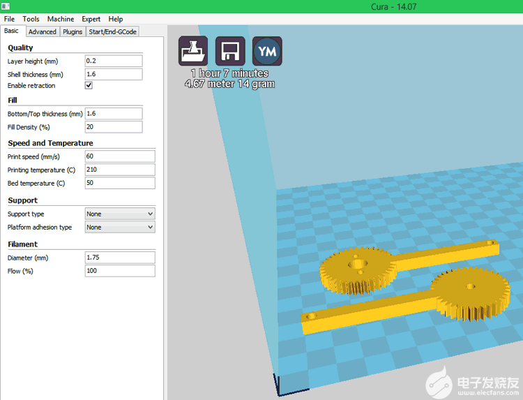
幸运的是,没有一个部件有悬垂结构,因此不需要支撑。设计非常简单,因此可以通过任何基本的3D打印机轻松处理。大约在打印 4.5 小时后,所有部件都可以组装了。组装说明再次由Ashing本身整齐地解释,因此我不打算涵盖它。
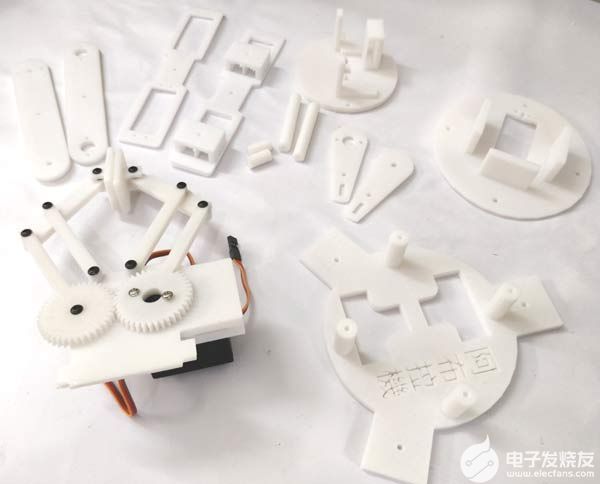
一个小提示是,您必须打磨/锉削零件的边缘才能使电机适合。所有电机都将通过一点机械力舒适地安装。要有耐心,如果电机看起来有点紧,请使用文件为电机腾出空间。您需要 20 个 3 毫米螺栓来组装机器人 ARM。
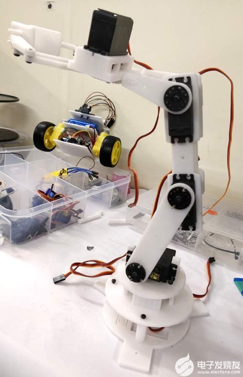
安装电机后,请确保它可以旋转并到达所需的位置,然后再永久拧紧。组装完成后,您可以继续延长前三个伺服电机的电线。我用公对母的电线来延长它们并将其带到电路板上。确保正确利用电线,以免它们在手臂工作时妨碍您。组装好后,我的机械臂在下图中看起来像这样。
电路图
MG995伺服电机以5V运行,Arduino板具有5V稳压器。因此,创建电路非常容易。我们必须将5 个伺服电机连接到 Arduino PWM 引脚,将 5 个电位计连接到 Arduino 模拟引脚以控制伺服电机。下面给出了相同的电路图。
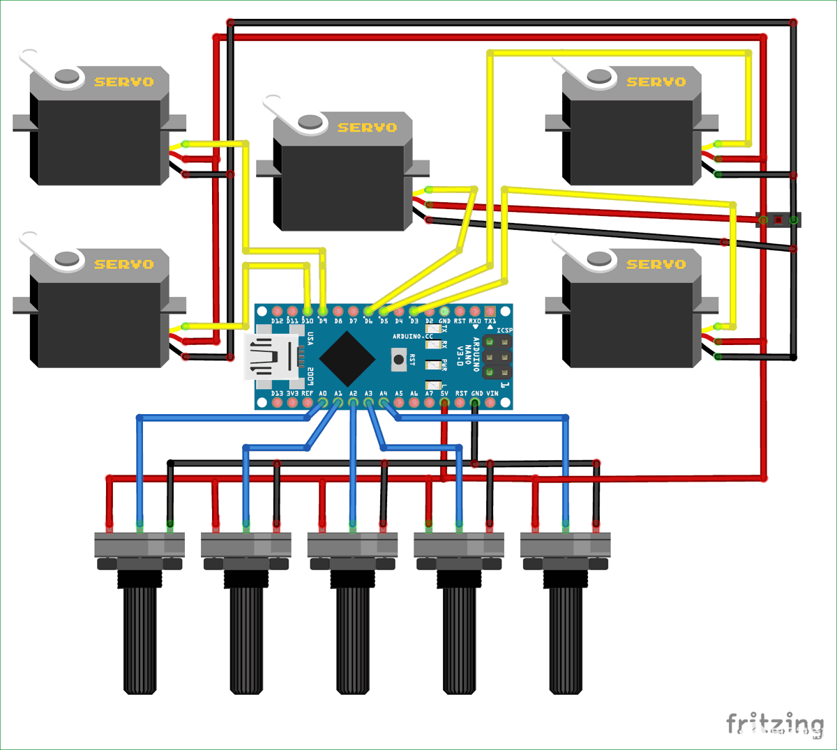
对于这个电路,我没有使用任何外部电源。Arduino通过USB端口供电,板上的+5v引脚用于为电位计和伺服电机供电。在我们的机械臂中,在任何给定的时间实例中,只有一个伺服电机将处于运动状态,因此消耗的电流将小于 150mA,这可以通过 Arduino 板的板载稳压器提供。
我们有5个伺服电机和5个电位器分别控制它们。这 5 个电位计连接到 Arduino 板的 5 个模拟引脚 A0 至 A4。伺服电机由PWM信号控制,因此我们必须将它们连接到Arduino的PWM引脚。在Arduino Nano上,引脚D3,D5,D6,D9和D11仅支持PWM,因此我们将前5个引脚用于伺服电机。我使用性能板焊接连接,完成后我的板如下所示。如果需要,我还添加了一个桶形插孔,通过电池为设备供电。但是,它是完全可选的。
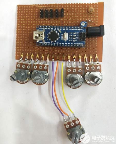
如果您完全不熟悉伺服电机和Arduino,那么建议您在继续项目之前阅读伺服电机基础知识和使用Arduino控制伺服文章。
为机械臂编程Arduino
现在,有趣的部分是对Arduino进行编程,以允许用户记录使用POT所做的动作,然后在需要时播放。为此,我们必须为两种模式对Arduino进行编程。一次是录制模式,另一个是播放模式。用户可以使用串行监视器在两种模式之间切换。可以在此页面底部找到执行相同操作的完整程序,您可以按原样使用该程序。但下面我用小片段解释了该程序,供您理解。
与往常一样,我们通过添加所需的头文件来开始程序。这里 Servo.h 头文件用于控制伺服电机。我们有 5 个伺服电机,因此声明了 5 个对象,为每个电机命名。我们还初始化将在程序中使用的变量。我已经将它们全部声明为全局的,但如果您有兴趣优化程序,可以更改它们的范围。我们还声明了一个名为 saved_data 的数组,顾名思义,该数组将保存机器人 ARM 的所有记录动作。
#include //Servo header file
//Declare object for 5 Servo Motors
Servo Servo_0;
Servo Servo_1;
Servo Servo_2;
Servo Servo_3;
Servo Gripper;
//Global Variable Declaration
int S0_pos, S1_pos, S2_pos, S3_pos, G_pos;
int P_S0_pos, P_S1_pos, P_S2_pos, P_S3_pos, P_G_pos;
int C_S0_pos, C_S1_pos, C_S2_pos, C_S3_pos, C_G_pos;
int POT_0,POT_1,POT_2,POT_3,POT_4;
int saved_data[700]; //Array for saving recorded data
int array_index=0;
char incoming = 0;
int action_pos;
int action_servo;
在空隙设置功能中,我们以 9600 波特率开始串行通信。我们还指定了伺服电机连接到的引脚。在我们的例子中,我们使用了使用附加函数指定的引脚 3、5、6、9 和 10。由于设置功能在启动期间运行,我们可以使用它将机械臂设置为启动位置。因此,我对所有五个电机的位置值进行了硬编码。这些硬编码值可以在以后根据您的喜好进行更改。在设置功能结束时,我们打印一个串行行,要求用户按 R 或 P 执行相应的操作
void setup() {
Serial.begin(9600); //Serial Monitor for Debugging
//Decalre the pins to which the Servo Motors are connected to
Servo_0.attach(3);
Servo_1.attach(5);
Servo_2.attach(6);
Servo_3.attach(9);
Gripper.attach(10);
//Write the servo motors to intial position
Servo_0.write(70);
Servo_1.write(100);
Servo_2.write(110);
Servo_3.write(10);
Gripper.write(10);
Serial.println("Press 'R' to Record and 'P' to play"); //Instrust the user
}
我定义了一个名为 Read_POT 的函数,它读取所有 5 个电位器的模拟值并将其映射到伺服位置值。众所周知,Arduino有一个8位ADC,它为我们提供0-1023的输出,但伺服电机位置值的范围仅为0-180。此外,由于这些伺服电机不是很精确,因此将它们驱动到极端的 0 端或 180 端是不安全的,因此我们将 10-170 设置为我们的极限。我们使用map函数将所有五个电机的0-1023转换为10-170,如下所示。
void Read_POT() //Function to read the Analog value form POT and map it to Servo value
{
POT_0 = analogRead(A0); POT_1 = analogRead(A1); POT_2 = analogRead(A2); POT_3 = analogRead(A3); POT_4 = analogRead(A4); //Read the Analog values form all five POT
S0_pos = map(POT_0,0,1024,10,170); //Map it for 1st Servo (Base motor)
S1_pos = map(POT_1,0,1024,10,170); //Map it for 2nd Servo (Hip motor)
S2_pos = map(POT_2,0,1024,10,170); //Map it for 3rd Servo (Shoulder motor)
S3_pos = map(POT_3,0,1024,10,170); //Map it for 4th Servo (Neck motor)
G_pos = map(POT_4,0,1024,10,170); //Map it for 5th Servo (Gripper motor)
}
录制模式代码
在记录模式下,用户必须使用电位计控制机器人。每个 POT 对应于一个单独的电机,由于电位器是不同的,我们应该将电机的位置和电机编号保存在saved_data阵列内。让我们看看如何使用记录功能实现这一点。
消除伺服抖动问题
使用这些伺服电机时,每个人都可能遇到的一个常见问题是电机在工作时可能会抖动。这个问题有很多解决方案,首先你要弄清楚问题是出在电机的控制电路上,还是与写入伺服电机的位置值有关。就我而言,我使用串行监视器,发现servo_pos的值不是恒定的,有时会随机上下抖动。
所以我对Arduino进行了编程,使其读取两次POT值并比较两个值。仅当两个值相同时,该值才会被视为有效,否则该值将被丢弃。值得庆幸的是,这为我解决了抖动问题。还要确保 POT 牢固地安装(我焊接了它)到 Arduino 的模拟引脚上。任何失去连接也会导致紧张。变量P_x_pos用于保存旧值,然后使用上面讨论的Read_POT函数再次读取和映射x_pos值。
Read_POT(); //Read the POT values for 1st time
//Save it in a varibale to compare it later
P_S0_pos = S0_pos;
P_S1_pos = S1_pos;
P_S2_pos = S2_pos;
P_S3_pos = S3_pos;
P_G_pos = G_pos;
Read_POT(); //Read the POT value for 2nd time
现在,如果值有效,我们必须控制伺服电机的位置。同样在控制之后,我们必须将电机编号和电机位置保存在阵列中。我们本可以使用两个不同的数组,一个用于电机编号,另一个用于其位置,但为了节省内存和复杂性,我通过在将 pos 值保存到数组之前向 pos 值添加微分器值来组合它们。
if (P_S0_pos == S0_pos) //If 1st and 2nd value are same
{
Servo_0.write(S0_pos); //Control the servo
if (C_S0_pos != S0_pos) //If the POT has been turned
{
saved_data[array_index] = S0_pos + 0; //Save the new position to the array. Zero is added for zeroth motor (for understading purpose)
array_index++; //Increase the array index
}
C_S0_pos = S0_pos; //Saved the previous value to check if the POT has been turned
}
Sero_0的微分值为 0,Servo_1的微分值为 1000,同样Servo_3为 3000,Gripper 为 4000。下面显示了将微分器添加到位置值并保存到数组中的代码行。
saved_data[array_index] = S0_pos + 0; //Save the new position to the array. Zero is added for zeroth motor (for understading purpose)
saved_data[array_index] = S1_pos + 1000; //1000 is added for 1st servo motor as differentiater
saved_data[array_index] = S2_pos + 2000; //2000 is added for 2nd servo motor as differentiater
saved_data[array_index] = S3_pos + 3000; //3000 is added for 3rd servo motor as differentiater
saved_data[array_index] = G_pos + 4000; //4000 is added for 4th servo motor as differentiater
播放模式代码
用户记录saved_data中的动作后,他可以通过在串行监视器中输入“P”来切换到播放模式。在播放模式下,我们可以访问保存在数组中的每个元素并拆分值以获取电机编号和电机位置并相应地控制它们的位置。
我们使用 for 循环来浏览数组的每个元素,直到保存在数组中的值。然后我们使用两个变量action_servo和action_pos分别得到要控制的伺服电机的数量及其位置。要获得伺服电机的数量,我们必须将其除以 1000 并得到位置,我们需要最后三位数字,这可以通过取模数获得。
例如,如果数组中保存的值是 3125,则表示 3RD电机必须移动到 125 的位置。
for (int Play_action=0; Play_action
{
action_servo = saved_data[Play_action] / 1000; //The fist charector of the array element is split for knowing the servo number
action_pos = saved_data[Play_action] % 1000; //The last three charectors of the array element is split to know the servo postion
现在剩下的就是使用舵机编号并将其移动到获得的伺服位置值。我使用开关盒进入相应的伺服电机编号和写入功能将伺服电机移动到该位置。开关外壳如下所示
switch(action_servo){ //Check which servo motor should be controlled
case 0: //If zeroth motor
Servo_0.write(action_pos);
break;
case 1://If 1st motor
Servo_1.write(action_pos);
break;
case 2://If 2nd motor
Servo_2.write(action_pos);
break;
case 3://If 3rd motor
Servo_3.write(action_pos);
break;
case 4://If 4th motor
Gripper.write(action_pos);
break;
主循环功能
在主循环功能内部,我们只需要检查用户通过串行监视器输入的内容并相应地执行播放模式的记录模式。变量传入用于保存用户的值。如果输入“R”,则记录模式将被激活,如果按下“P”,则播放模式将由if条件语句执行,如下所示。
void loop() {
if (Serial.available() > 1) //If something is recevied from serial monitor
{
incoming = Serial.read();
if (incoming == 'R')
Serial.println("Robotic Arm Recording Started......");
if (incoming == 'P')
Serial.println("Playing Recorded sequence");
}
if (incoming == 'R') //If user has selected Record mode
Record();
if (incoming == 'P') //If user has selected Play Mode
Play();
}
记录和播放机器人手臂的工作
按照电路图中所示进行连接,并上传下面给出的代码。通过计算机的USB端口为您的Arduino Nano供电,然后打开串行显示器,您将受到此介绍消息的欢迎。

现在在串行监视器中输入 R,然后按回车键。请注意,应选择串行监视器底部的换行符。进入后,机器人将进入录制模式,您将看到以下屏幕。
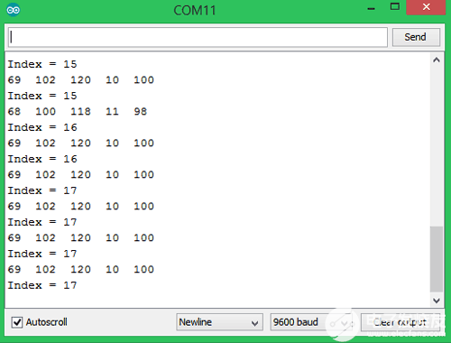
此处显示的信息可用于调试。从形式 69 开始的数字是伺服电机 0 到电机 5 的当前位置。索引值适用于数组大小。请注意,我们使用的数组限制为 700,因此我们在超过该限制之前已完成记录运动。录制完成后,我们可以在串行监视器中输入P并按回车键,我们将进入播放模式,串行监视器将显示以下内容。
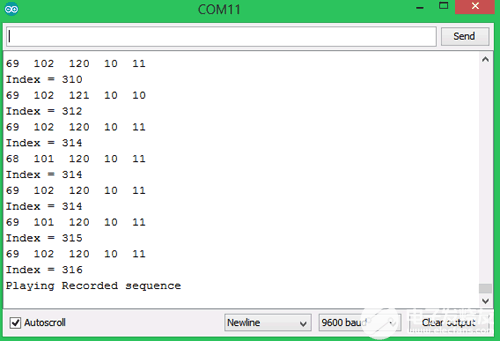
在播放模式下,机器人将重复在录制模式下完成的相同动作。这些动作将一次又一次地执行,直到您通过串行监视器中断它。
/*
Robotic ARM with Record and Play option using Arduino
Code by: B. Aswinth Raj
Website: www.circuitdigest.com
Dated: 05-08-2018
*/
#include //Servo header file
//Declare object for 5 Servo Motors
Servo Servo_0;
Servo Servo_1;
Servo Servo_2;
Servo Servo_3;
Servo Gripper;
//Global Variable Declaration
int S0_pos, S1_pos, S2_pos, S3_pos, G_pos;
int P_S0_pos, P_S1_pos, P_S2_pos, P_S3_pos, P_G_pos;
int C_S0_pos, C_S1_pos, C_S2_pos, C_S3_pos, C_G_pos;
int POT_0,POT_1,POT_2,POT_3,POT_4;
int saved_data[700]; //Array for saving recorded data
int array_index=0;
char incoming = 0;
int action_pos;
int action_servo;
void setup() {
Serial.begin(9600); //Serial Monitor for Debugging
//Declare the pins to which the Servo Motors are connected to
Servo_0.attach(3);
Servo_1.attach(5);
Servo_2.attach(6);
Servo_3.attach(9);
Gripper.attach(10);
//Write the servo motors to initial position
Servo_0.write(70);
Servo_1.write(100);
Servo_2.write(110);
Servo_3.write(10);
Gripper.write(10);
Serial.println("Press 'R' to Record and 'P' to play"); //Instruct the user
}
void Read_POT() //Function to read the Analog value form POT and map it to Servo value
{
POT_0 = analogRead(A0); POT_1 = analogRead(A1); POT_2 = analogRead(A2); POT_3 = analogRead(A3); POT_4 = analogRead(A4); //Read the Analog values form all five POT
S0_pos = map(POT_0,0,1024,10,170); //Map it for 1st Servo (Base motor)
S1_pos = map(POT_1,0,1024,10,170); //Map it for 2nd Servo (Hip motor)
S2_pos = map(POT_2,0,1024,10,170); //Map it for 3rd Servo (Shoulder motor)
S3_pos = map(POT_3,0,1024,10,170); //Map it for 4th Servo (Neck motor)
G_pos = map(POT_4,0,1024,10,170); //Map it for 5th Servo (Gripper motor)
}
void Record() //Function to Record the movements of the Robotic Arm
{
Read_POT(); //Read the POT values for 1st time
//Save it in a variable to compare it later
P_S0_pos = S0_pos;
P_S1_pos = S1_pos;
P_S2_pos = S2_pos;
P_S3_pos = S3_pos;
P_G_pos = G_pos;
Read_POT(); //Read the POT value for 2nd time
if (P_S0_pos == S0_pos) //If 1st and 2nd value are same
{
Servo_0.write(S0_pos); //Control the servo
if (C_S0_pos != S0_pos) //If the POT has been turned
{
saved_data[array_index] = S0_pos + 0; //Save the new position to the array. Zero is added for zeroth motor (for understading purpose)
array_index++; //Increase the array index
}
C_S0_pos = S0_pos; //Saved the previous value to check if the POT has been turned
}
//Similarly repeat for all 5 servo Motors
if (P_S1_pos == S1_pos)
{
Servo_1.write(S1_pos);
if (C_S1_pos != S1_pos)
{
saved_data[array_index] = S1_pos + 1000; //1000 is added for 1st servo motor as differentiator
array_index++;
}
C_S1_pos = S1_pos;
}
if (P_S2_pos == S2_pos)
{
Servo_2.write(S2_pos);
if (C_S2_pos != S2_pos)
{
saved_data[array_index] = S2_pos + 2000; //2000 is added for 2nd servo motor as differentiator
array_index++;
}
C_S2_pos = S2_pos;
}
if (P_S3_pos == S3_pos)
{
Servo_3.write(S3_pos);
if (C_S3_pos != S3_pos)
{
saved_data[array_index] = S3_pos + 3000; //3000 is added for 3rd servo motor as differentiater
array_index++;
}
C_S3_pos = S3_pos;
}
if (P_G_pos == G_pos)
{
Gripper.write(G_pos);
if (C_G_pos != G_pos)
{
saved_data[array_index] = G_pos + 4000; //4000 is added for 4th servo motor as differentiator
array_index++;
}
C_G_pos = G_pos;
}
//Print the value for debugging
Serial.print(S0_pos); Serial.print(" "); Serial.print(S1_pos); Serial.print(" "); Serial.print(S2_pos); Serial.print(" "); Serial.print(S3_pos); Serial.print(" "); Serial.println(G_pos);
Serial.print ("Index = "); Serial.println (array_index);
delay(100);
}
void Play() //Functon to play the recorded movements on the Robotic ARM
{
for (int Play_action=0; Play_action
{
action_servo = saved_data[Play_action] / 1000; //The fist character of the array element is split for knowing the servo number
action_pos = saved_data[Play_action] % 1000; //The last three characters of the array element is split to know the servo postion
switch(action_servo){ //Check which servo motor should be controlled
case 0: //If zeroth motor
Servo_0.write(action_pos);
break;
case 1://If 1st motor
Servo_1.write(action_pos);
break;
case 2://If 2nd motor
Servo_2.write(action_pos);
break;
case 3://If 3rd motor
Servo_3.write(action_pos);
break;
case 4://If 4th motor
Gripper.write(action_pos);
break;
}
delay(50);
}
}
void loop() {
if (Serial.available() > 1) //If something is received from serial monitor
{
incoming = Serial.read();
if (incoming == 'R')
Serial.println("Robotic Arm Recording Started......");
if (incoming == 'P')
Serial.println("Playing Recorded sequence");
}
if (incoming == 'R') //If user has selected Record mode
Record();
if (incoming == 'P') //If user has selected Play Mode
Play();
}
-
构建3D打印机械臂的教程2022-08-03 1673
-
用于创建3D打印机械臂的开源项目2022-07-20 851
-
CM6兼容的3D打印机械臂2022-07-12 960
-
哪种3d打印机精度高 哪家3d打印机性价比高2021-11-22 8488
-
怎样去设计一种基于3D打印机的Delta机械臂2021-10-11 1925
-
3D打印机原理2021-09-08 2723
-
选购3D打印机时应该注意哪些问题2021-07-24 1509
-
浅谈影响3D打印机价格的因素2021-06-06 2127
-
新手该怎样使用小型3d打印机2020-12-04 4736
-
3d打印机可以打印什么东西_3d打印机怎么用2020-03-21 13104
-
3D打印机的简介2019-12-06 12544
-
开源3D打印机开发套件2015-10-23 5008
-
为什么没人用stm32做3d打印机2014-09-15 18240
-
制作3D打印机2014-06-05 6340
全部0条评论

快来发表一下你的评论吧 !

