

 瑞萨e2studio(3)----GPIO输入检测
描述
概述
本篇文章主要介绍如何使用e2studio对瑞萨单片机进行GPIO输出,并以LED显示。
视频教学
听不到声音的请点击跳转进行观看。
[video(video-4XyyvLft-1649445510098)(type-bilibili)(url-https://player.bilibili.com/player.html?aid=634677043)(image-https://img-blog.csdnimg.cn/img_convert/0a2553dda92a0734aabad89d3a8f508d.png)(title-瑞萨e2studio(6)----GPIO输入检测(image-https://img-blog.csdnimg.cn/img_convert/0a2553dda92a0734aabad89d3a8f508d.png)(title-%E7%91%9E%E8%90%A8e2studio(6)----GPIO%E8%BE%93%E5%85%A5%E6%A3%80%E6%B5%8B))]
硬件准备
首先需要准备一个开发板,这里我准备的是芯片型号R7FA4M2AD3CFP的开发板: 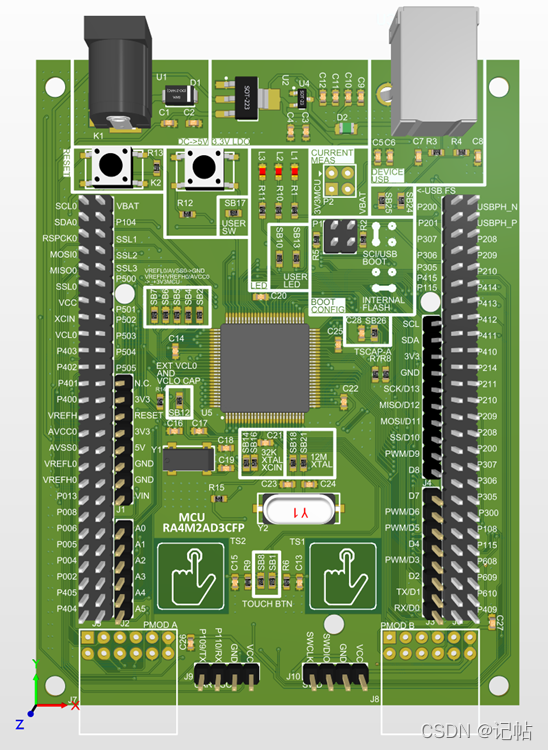
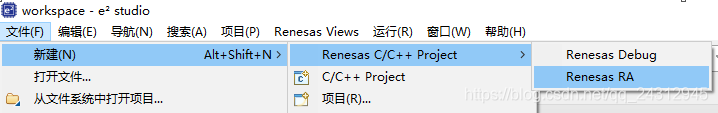
新建工程
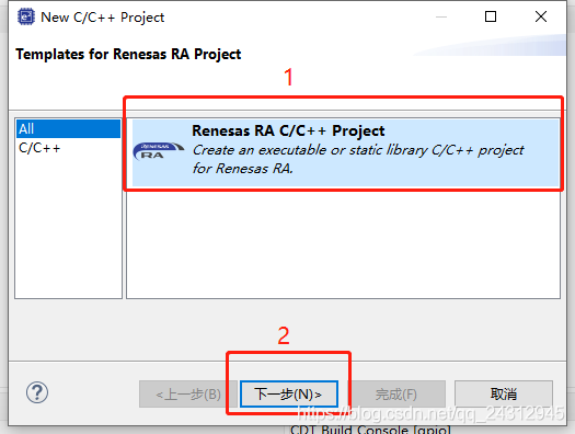
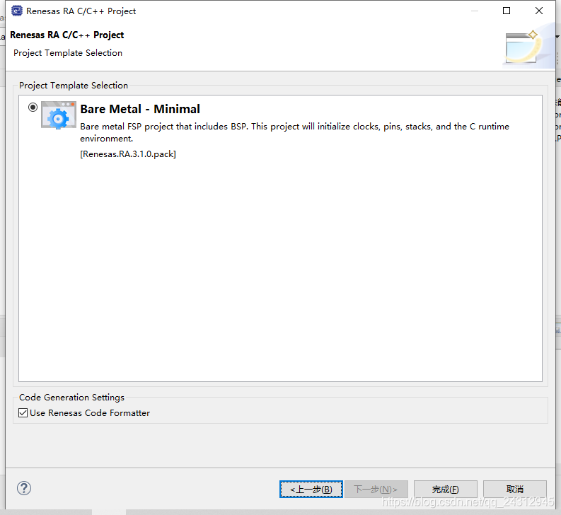
工程模板
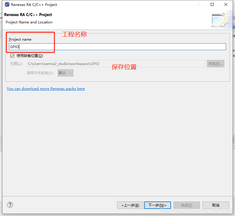
保存工程路径
芯片配置
本文中使用R7FA2L1AB2DFL来进行演示。 
工程模板选择
GPIO口配置
由下图我们可以得知,板子上有2个LED灯,同时需要给高电平才可以点亮,故以P301和P302管脚为例。 
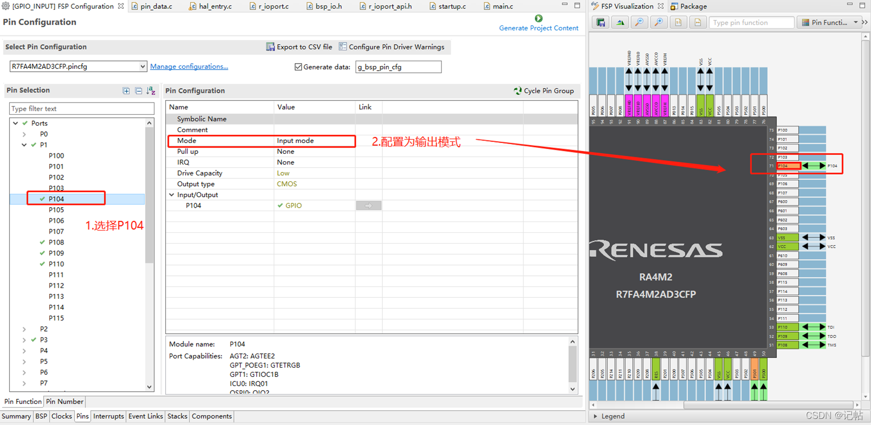
按键口配置
由下图我们可以得知,按键在P104管脚,并且有一个上拉。 
按键口&Led配置
案例:当按下按键P104,P301亮,否则P301灭。 
R_IOPORT_PortRead()函数原型
fsp_err_t R_IOPORT_PortRead    (    ioport_ctrl_t *const     p_ctrl,
bsp_io_port_t     port,
ioport_size_t *     p_port_value
)

说明:
Reads the value on an IO port. Implements ioport_api_t::portRead.

The specified port will be read, and the levels for all the pins will be returned. Each bit in the returned value corresponds to a pin on the port. For example, bit 7 corresponds to pin 7, bit 6 to pin 6, and so on.
故可以用R_IOPORT_PortRead()函数进行读取IO口电平状态,该函数是把一个PORT口的16个端口一起读取出来。
ioport_size_t p_port_value_port_104;
R_IOPORT_PortRead(&g_ioport_ctrl, BSP_IO_PORT_01, &p_port_value_port_104);
R_IOPORT_PinRead()函数原型
fsp_err_t R_IOPORT_PinRead    (    ioport_ctrl_t *const     p_ctrl,
bsp_io_port_pin_t     pin,
bsp_io_level_t *     p_pin_value
)

说明:
Reads the level on a pin. Implements ioport_api_t::pinRead.
故可以用R_IOPORT_PinRead()函数进行读取IO口电平状态,该函数只能读取一个端口的电平。
bsp_io_level_t p_port_value_port_104_1;
R_IOPORT_PinRead(&g_ioport_ctrl, BSP_IO_PORT_01_PIN_04, &p_port_value_port_104_1);
由上述可以得知,R_IOPORT_PortRead完全可以替代R_IOPORT_PinRead。
代码
在hal_entry()中添加如下。
#include "hal_data.h"

FSP_CPP_HEADER
void R_BSP_WarmStart(bsp_warm_start_event_t event);
FSP_CPP_FOOTER

/*******************************************************************************************************************//**
 * main() is generated by the RA Configuration editor and is used to generate threads if an RTOS is used.  This function
 * is called by main() when no RTOS is used.
 **********************************************************************************************************************/
void hal_entry(void)
{
    /* TODO: add your own code here */
    fsp_err_t      err;
    /* Initialize the IOPORT module and configure the pins
     * Note: The default pin configuration name in the RA Configuraton tool is g_bsp_pin_cfg */
    err = R_IOPORT_Open(&g_ioport_ctrl, &g_bsp_pin_cfg);
    /* Handle any errors. This function should be defined by the user. */
    assert(FSP_SUCCESS == err);
    ioport_size_t p_port_value_port_104;
    bsp_io_level_t p_port_value_port_104_1;
    while(1)
    {

//     R_IOPORT_PortRead(&g_ioport_ctrl, BSP_IO_PORT_01, &p_port_value_port_104);
//     if(p_port_value_port_104 & 0x0010)
//         R_IOPORT_PinWrite(&g_ioport_ctrl, BSP_IO_PORT_03_PIN_01, BSP_IO_LEVEL_LOW);
//     else
//         R_IOPORT_PinWrite(&g_ioport_ctrl, BSP_IO_PORT_03_PIN_01, BSP_IO_LEVEL_HIGH);

        R_IOPORT_PinRead(&g_ioport_ctrl, BSP_IO_PORT_01_PIN_04, &p_port_value_port_104_1);
        if(p_port_value_port_104_1)//BSP_IO_LEVEL_HIGH 没按下
            R_IOPORT_PinWrite(&g_ioport_ctrl, BSP_IO_PORT_03_PIN_01, BSP_IO_LEVEL_LOW);
        else
            R_IOPORT_PinWrite(&g_ioport_ctrl, BSP_IO_PORT_03_PIN_01, BSP_IO_LEVEL_HIGH);
    }
#if BSP_TZ_SECURE_BUILD
    /* Enter non-secure code */
    R_BSP_NonSecureEnter();
#endif
}
以上的代码会在Q_QUN里分享。Q_QUN:615061293。 或者关注『记帖』,持续更新文章和学习资料!
-
 记帖MCU
2022-11-18
0 回复 举报交流ⓆU_N:6_15061293 收起回复
记帖MCU
2022-11-18
0 回复 举报交流ⓆU_N:6_15061293 收起回复
-
瑞萨e2studio(1)----瑞萨芯片之搭建FSP环境2024-09-30 6953
-
如何使用e2studio对瑞萨单片机进行GPIO输出2024-07-30 2247
-
瑞萨e2studio(25)----电容触摸配置(2)2023-08-21 2227
-
瑞萨e2studio(8)----PWM2022-11-15 2598
-
如何使用e2studio对瑞萨单片机进行GPIO输出并以LED显示?2022-02-16 1713
-
瑞萨e2studio(2)----GPIO输出2021-12-20 963
-
瑞萨e2studio----GPIO输出2021-11-03 2628
全部0条评论

快来发表一下你的评论吧 !
