

基于PIC16F877A微控制器构建的数字闹钟
描述
始于1950年的数字革命将所有现有的机械和模拟电子结构转变为数字计算机。由于数字电子产品的增长呈指数级增长,今天一个人几乎不可能抗拒使用任何电子设备。从叫醒你的闹钟和为你提供早餐的烤面包机开始,一切都是数字电子产品的贡献。考虑到所有这些,对我们自己的东西进行编程真的很令人兴奋,这些东西可以完成简单而有用的任务,比如我们将在这个项目中使用PIC 微控制器构建的闹钟。
该闹钟将有一个 16x2 LCD 显示屏,将显示当前时间和设置时间。我们将在需要时使用几个按钮来设置闹钟时间。使用DS3231RTC模块可以跟踪当前时间,我们将使用IIC通信从RTC模块获取这些值。我们已经了解了 RTC 模块以及如何将其与 PIC 接口。因此,建议通读该教程,我们将跳过该教程中涵盖的大部分信息。
所需材料:
面包板 – 2Nos
PIC16F877A
5V 电源 - 电源模块
20兆赫晶体
33pf 电容器 – 2 常开
DS3231 RTC 模块
16*2液晶显示模块
10K 锅
10k 和 1K 电阻
按钮 – 5 否
蜂鸣器
连接线
先决条件:
本项目要求您了解一些有关PIC微控制器以及如何对其进行编程的基础知识。我们将在这个项目中使用GPIO,LCD显示器和RTC模块。因此,最好事先学习如何使用这些模块。
电路图:
这个基于PIC的闹钟项目的电路图如下所示,该项目是使用proteus软件创建的。该项目还将用于进一步的仿真。
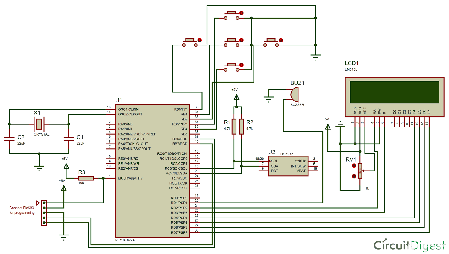
五个按钮将作为输入,用于将闹钟设置为所需时间。因此,所有按钮的一端接地,另一端连接到PORTB引脚,这些引脚上将使用内部上拉电阻,以避免引脚浮动。蜂鸣器将充当输出,并在警报被触发并连接到 PORT S 引脚时给我们发出哔哔声。当前时间始终由DS3231RTC模块跟踪,PIC通过I2C总线从该模块接收数据,因此RTC模块的SCL和SDA引脚连接到PIC控制器的SCL和SDA引脚。LCD显示器连接到PIC的PORTD,用于显示当前时间和设定时间。在此处了解有关DS3231 RTC模块与PIC配合使用的更多信息。
整个电路可以构建在面包板上。由于有几十根电线要连接,所以请耐心等待并确保连接正确。完成连接后,我的硬件设置如下所示
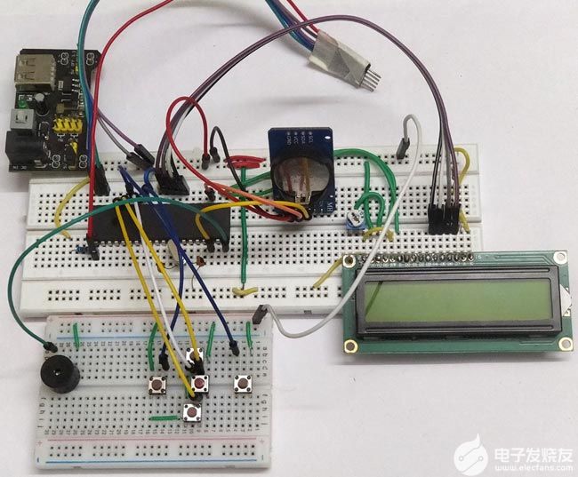
我使用面包板模块和 12V 适配器为模块供电。这是我的+5V电源电压源。此外,我还必须使用两个面包板来保持电路清洁。如果您希望制作更强大的项目,您还可以将整个电路焊接到性能板上。
闹钟编程:
此闹钟项目的完整PIC程序可以在此页面底部找到。该项目还需要三个库来使用LCD,I2C和RTC和PIC。
在进入主程序之前,我们必须定义使用更有意义的名称使用的引脚。这样,在编程过程中就很容易使用它们。我们程序中定义的引脚如下所示
//Define the LCD pins
#define RS RD2 //Reset pin of LCD
#define EN RD3 //Enable pin of LCD
#define D4 RD4 //Data bit 0 of LCD
#define D5 RD5 //Data bit 1 of LCD
#define D6 RD6 //Data bit 2 of LCD
#define D7 RD7 //Data bit 3 of LCD
//Define Buttons
#define MB RB1 //The middle button
#define LB RB0 //Left button
#define RB RB2 //Right button
#define UB RB3 //Upper Button
#define BB RB4 //Bottom button
//Define Buzz
#define BUZZ RD1 //Buzzer is connected to RD1
在 main 函数中,我们首先声明输入和输出引脚。在我们的项目中,PORTB 用于按钮,这是一个输入设备,因此我们将它们的引脚设置为输入,PORTD 用于 LCD 和蜂鸣器,因此我们将它们的引脚设置为输出。此外,引脚不应悬空,I/O引脚应始终连接到地或+5V电压。在我们的例子中,对于按钮,当按钮未按下时,引脚不会连接到任何东西,因此我们使用内部上拉电阻器,该电阻器在不使用时将引脚设置为高电平。这是使用控制寄存器完成的,如下所示
TRISD = 0x00; //Make Port D pins as outptu for LCD interfacing
TRISB = 0xFF; //Switchs are declared as input pins
OPTION_REG = 0b00000000; //Enable pull up Resistor on port B for switchs
BUZZ = 0; //Turn of buzzer
由于我们有与主程序链接的LCD和I2C头文件,因此我们可以通过调用一个简单的函数来开始LCD初始化。I2C初始化也可以这样做。在这里,我们以 100kHz 开始 I2C 通信,因为 RTC 模块以 100kHz 工作。
Lcd_Start(); // Initialize LCD module
I2C_Initialize(100); //Initialize I2C Master with 100KHz clock
下面的函数用于在RTC模块上设置时间和日期,一旦设置了时间和日期,请删除此行。否则,每次启动程序时,都会一次又一次地设置时间和日期
//Remove the below line once time and date is set for the first time.
Set_Time_Date(); //set time and date on the RTC module
为了指示程序正在启动,我们显示一个小的介绍屏幕,其中显示项目名称和网站名称,如下所示
//Give an intro message on the LCD
Lcd_Clear();
Lcd_Set_Cursor(1,1);
Lcd_Print_String("Alarm Clock");
Lcd_Set_Cursor(2,1);
Lcd_Print_String(" -Circuit Digest");
__delay_ms(1500);
接下来在 while 循环中,我们需要从 RTC 模块读取当前时间和日期,这可以通过调用以下函数来完成。
Update_Current_Date_Time(); //Read the current date and time from RTC module
调用上述函数将使用当前值更新变量 sec、min 和 hour。为了在LCD屏幕上显示它们,我们必须使用以下代码将它们拆分为单个字符。
//Split the into char to display on lcd
char sec_0 = sec % 10;
char sec_1 = (sec / 10);
char min_0 = min % 10;
char min_1 = min / 10;
char hour_0 = hour % 10;
char hour_1 = hour / 10;
接下来,我们更新LCD屏幕上的值。当前时间将显示在第一行,必须触发警报的设置时间显示在第二行。执行相同操作的代码如下所示。
//Display the Current Time on the LCD screen
Lcd_Clear();
Lcd_Set_Cursor(1, 1);
Lcd_Print_String("TIME: ");
Lcd_Print_Char(hour_1 + '0');
Lcd_Print_Char(hour_0 + '0');
Lcd_Print_Char(':');
Lcd_Print_Char(min_1 + '0');
Lcd_Print_Char(min_0 + '0');
Lcd_Print_Char(':');
Lcd_Print_Char(sec_1 + '0');
Lcd_Print_Char(sec_0 + '0');
//Display the Date on the LCD screen
Lcd_Set_Cursor(2, 1);
Lcd_Print_String("Alarm: ");
Lcd_Print_Char(alarm_val[0] + '0');
Lcd_Print_Char(alarm_val[1] + '0');
Lcd_Print_Char(':');
Lcd_Print_Char(alarm_val[2] + '0');
Lcd_Print_Char(alarm_val[3] + '0');
现在,我们已经在LCD上显示了时间和设置时间,我们必须检查用户是否正在尝试设置闹钟时间。为此,用户必须按下中间按钮,因此我们将检查是否按下中间按钮并切换变量以进入警报设置模式。将再次按下相同的按钮以确认已设置值,在这种情况下,我们必须退出警报设置模式。因此,我们使用下面的代码行来更改变量set_alarm的状态。
//Use middle button to check if alarm has to be set
if (MB == 0 && set_alarm == 0) { //If middle button is pressed and alarm is not turned on
while (!MB); //Wait till button is released
set_alarm = 1; //start setting alarm value
}
if (MB == 0 && set_alarm == 1) { //If middle button is pressed and alarm is not turned off
while (!MB); //Wait till button is released
set_alarm = 0; //stop setting alarm value
}
如果用户按下了中间按钮,则表示他正在尝试设置闹钟时间。在这种情况下,程序使用上面的代码进入警报设置模式。在警报设置模式下,如果用户按下左或右按钮,则意味着我们必须向左或向右移动光标。为此,我们只需递增递减光标必须放置的位置值
if (LB == 0) { //If left button is pressed
while (!LB); //Wait till button is released
pos--; //Then move the cursor to left
}
if (RB == 0) { //If right button is pressed
while (!RB); //Wait till button is released
pos++; //Move cursor to right
}
在将按钮与微控制器或微处理器一起使用时,有一个常见问题需要解决。此问题称为开关弹跳。也就是说,当按下按钮时,它可能会给MCU / MPU发出嘈杂的脉冲,这可能会伪造MCU的多个条目。这个问题可以通过在开关上增加一个电容或在检测到按钮按下后立即使用延迟功能来解决。这种类型的解决方案称为去抖动。在这里,我们使用了一个while循环来将程序固定到位,直到按钮被释放。这不是最好的去抖动解决方案,但对我们来说,它会很好地工作。
while (!RB);
与左右按钮类似,我们也有上下按钮,可用于增加或减少闹钟时间的值。执行相同操作的代码如下所示。请注意,设置的警报时间的每个字符都由数组的索引值寻址。这是我们可以轻松访问必须更改其值的所需字符。
if (UB == 0) { //If upper button is pressed
while (!UB); //Wait till button is released
alarm_val[(pos - 8)]++; //Increase that particular char value
}
if (BB == 0) { //If lower button is pressed
while (!UB); //Wait till button is released
alarm_val[(pos - 8)]--; //Decrease that particular char value
}
设置闹钟时间后,用户将再次短按中间按钮。然后我们可以开始将当前时间与设置的时间进行比较。通过检查当前时间的每个字符是否等于设置时间的字符来进行比较。如果值相等,那么我们通过设置 trigger_alarm 变量来触发警报,否则我们只是比较直到它相等。
//IF alarm is set Check if the set value is equal to current value
if (set_alarm == 0 && alarm_val[0] == hour_1 && alarm_val[1] == hour_0 && alarm_val[2] == min_1 && alarm_val[3] == min_0)
trigger_alarm = 1; //Turn on trigger if value match
如果设置了警报,我们必须发出蜂鸣器以提醒用户警报。这可以通过简单地定期切换蜂鸣器来完成,如下所示。
if (trigger_alarm) { //If alarm is triggered
//Beep the buzzer
BUZZ = 1;
__delay_ms(500);
BUZZ = 0;
__delay_ms(500);
}
模拟:
该程序也可以使用变形虫软件进行模拟。只需重新创建上面显示的电路,并将十六进制文件加载到 PIC 中即可。
模拟期间拍摄的屏幕截图如下所示
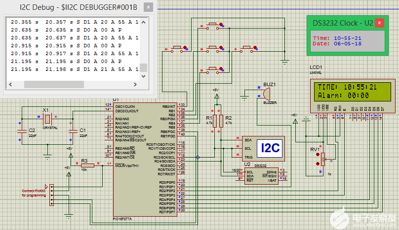
当您尝试向项目添加新功能时,模拟变得非常有用。您 还 可以 使用 I2C 调试 器 模 块 来 检查 哪些 数据 通过 I2C 总 线 进出。您可以尝试按下按钮并设置闹钟时间。当设定的时间等于当前时间时,蜂鸣器将变高。
使用PIC16F877A的数字闹钟工作:
在试验板上构建电路,从下载链接获取代码并使用MplabX和XC8编译器进行编译。
编译后,使用PicKit3编程器将程序上传到您的硬件。电路图中还显示了将拾取器编程器连接到PIC IC的连接。程序上传后,您应该会看到介绍屏幕,然后显示时间,然后您可以使用按钮设置闹钟时间。通电时的硬件设置如下所示。
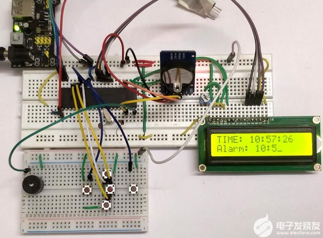
当闹钟时间与当前时间匹配时,蜂鸣器将开始发出蜂鸣声以提醒用户。完整的工作可以在下面的视频中找到。该项目有很多选择可以构建。RTC 模块可以跟踪任何时间和日期,因此您可以在所需的任何时间/日期执行计划任务。您还可以连接风扇或灯等交流电器,并在需要时安排其打开或关闭。
/*
* Program: Alarm Clock Using PIC
* Author: B.Aswinth Raj
* More info: www.circuitdigest.com
* Created on 11 May, 2018, 3:02 PM
*/
#pragma config FOSC = HS // Oscillator Selection bits (HS oscillator)
#pragma config WDTE = OFF // Watchdog Timer Enable bit (WDT disabled)
#pragma config PWRTE = ON // Power-up Timer Enable bit (PWRT enabled)
#pragma config BOREN = ON // Brown-out Reset Enable bit (BOR enabled)
#pragma config LVP = OFF // Low-Voltage (Single-Supply) In-Circuit Serial Programming Enable bit (RB3 is digital I/O, HV on MCLR must be used for programming)
#pragma config CPD = OFF // Data EEPROM Memory Code Protection bit (Data EEPROM code protection off)
#pragma config WRT = OFF // Flash Program Memory Write Enable bits (Write protection off; all program memory may be written to by EECON control)
#pragma config CP = OFF // Flash Program Memory Code Protection bit (Code protection off)
#define _XTAL_FREQ 20000000 //We are running on 20MHz crystal
//Define the LCD pins
#define RS RD2 //Reset pin of LCD
#define EN RD3 //Enable pin of LCD
#define D4 RD4 //Data bit 0 of LCD
#define D5 RD5 //Data bit 1 of LCD
#define D6 RD6 //Data bit 2 of LCD
#define D7 RD7 //Data bit 3 of LCD
//Define Buttons
#define MB RB1 //The middle button
#define LB RB0 //Left button
#define RB RB2 //Right button
#define UB RB3 //Upper Button
#define BB RB4 //Bottom button
//Define Buzz
#define BUZZ RD1 //Buzzer is connected to RD1
/*Set the current value of date and time below*/
int sec = 00;
int min = 55;
int hour = 10;
int date = 06;
int month = 05;
int year = 18;
/*Time and Date Set*/
/*Vars for Alarm clock*/
char set_alarm = 0;
char trigger_alarm = 0;
char pos = 8;
char jump = 0;
char alarm_h0 = 0;
char alarm_h1 = 0;
char alarm_m0 = 0;
char alarm_m1 = 0;
int alarm_val[4] = {0, 0, 0, 0};
/*End of var declaration*/
#include
#include "lcd.h" //Header for using LCD module
#include "PIC16F877a_I2C.h" // Header for using I2C protocal
#include "PIC16F877a_DS3231.h" //Header for using DS3231 RTC module
int main() {
TRISD = 0x00; //Make Port D pins as outptu for LCD interfacing
TRISB = 0xFF; //Switchs are declared as input pins
OPTION_REG = 0b00000000; //Enable pull up Resistor on port B for switchs
BUZZ = 0; //Turn of buzzer
Lcd_Start(); // Initialize LCD module
I2C_Initialize(100); //Initialize I2C Master with 100KHz clock
//Remove the below line once time and date is set for the first time.
Set_Time_Date(); //set time and date on the RTC module
//Give an intro message on the LCD
Lcd_Clear();
Lcd_Set_Cursor(1,1);
Lcd_Print_String("Alarm Clock");
Lcd_Set_Cursor(2,1);
Lcd_Print_String(" -Circuit Digest");
__delay_ms(1500);
while (1) {
Update_Current_Date_Time(); //Read the current date and time from RTC module
//Split the into char to display on lcd
char sec_0 = sec % 10;
char sec_1 = (sec / 10);
char min_0 = min % 10;
char min_1 = min / 10;
char hour_0 = hour % 10;
char hour_1 = hour / 10;
//Display the Current Time on the LCD screen
Lcd_Clear();
Lcd_Set_Cursor(1, 1);
Lcd_Print_String("TIME: ");
Lcd_Print_Char(hour_1 + '0');
Lcd_Print_Char(hour_0 + '0');
Lcd_Print_Char(':');
Lcd_Print_Char(min_1 + '0');
Lcd_Print_Char(min_0 + '0');
Lcd_Print_Char(':');
Lcd_Print_Char(sec_1 + '0');
Lcd_Print_Char(sec_0 + '0');
//Display the Date on the LCD screen
Lcd_Set_Cursor(2, 1);
Lcd_Print_String("Alarm: ");
Lcd_Print_Char(alarm_val[0] + '0');
Lcd_Print_Char(alarm_val[1] + '0');
Lcd_Print_Char(':');
Lcd_Print_Char(alarm_val[2] + '0');
Lcd_Print_Char(alarm_val[3] + '0');
__delay_ms(50);
//Use middle button to check if alarm has to be set
if (MB == 0 && set_alarm == 0) { //If middle button is pressed and alarm is not turned on
while (!MB); //Wait till button is released
set_alarm = 1; //start setting alarm value
}
if (MB == 0 && set_alarm == 1) { //If middle button is pressed and alarm is not turned off
while (!MB); //Wait till button is released
set_alarm = 0; //stop setting alarm value
}
//If alarm has to be navigate through each digit
if (set_alarm == 1) {
if (LB == 0) { //If left button is pressed
while (!LB); //Wait till button is released
pos--; //Then move the cursor to left
}
if (RB == 0) { //If right button is pressed
while (!RB); //Wait till button is released
pos++; //Move cursor to right
}
if (pos >= 10) //eliminate ":" symbol if cursor reaches there
{
jump = 1; //Jump over the ":" symbol
} else
jump = 0; //get back to normal movement
if (UB == 0) { //If upper button is pressed
while (!UB); //Wait till button is released
alarm_val[(pos - 8)]++; //Increase that particular char value
}
if (BB == 0) { //If lower button is pressed
while (!UB); //Wait till button is released
alarm_val[(pos - 8)]--; //Decrease that particular char value
}
Lcd_Set_Cursor(2, pos + jump);
Lcd_Print_Char(95); //Display "_" to indicate cursor position
}
//IF alarm is set Check if the set value is equal to current value
if (set_alarm == 0 && alarm_val[0] == hour_1 && alarm_val[1] == hour_0 && alarm_val[2] == min_1 && alarm_val[3] == min_0)
trigger_alarm = 1; //Turn on trigger if value match
if (trigger_alarm) { //If alarm is triggered
//Beep the buzzer
BUZZ = 1;
__delay_ms(500);
BUZZ = 0;
__delay_ms(500);
}
__delay_ms(200);//Update interval
}
return 0;
}
- 相关推荐
- 热点推荐
- 微控制器
- PIC16F877A
- 数字闹钟
-
PIC16F877A开发板原理图2023-03-21 882
-
如何在PIC16F877A微控制器中使用EEPROM保存数据2023-01-25 4561
-
PIC16F877A单片机代码生成系统2022-12-20 1004
-
如何使用PIC微控制器构建一个线路跟随机器人2022-11-30 2479
-
如何使用PIC微控制器旋转步进电机2022-11-15 2164
-
将继电器与PIC微控制器PIC16F877A连接的教程2022-11-14 5138
-
使用热敏打印机连接PIC16F877A并使用轻触开关实现打印的教程2022-11-04 5042
-
PIC16F877A开发板 普通IO驱动74595实验2021-11-16 975
-
PIC16F877A的T0定时器制作的电子钟程序2020-05-15 2361
-
PIC16F877A串口发送查询方式2017-09-01 1149
-
基于PIC16F877A的太阳能与市电互补照明系统控制器的设2010-04-10 1572
-
pic16f877a中文资料pdf2008-07-15 27687
全部0条评论

快来发表一下你的评论吧 !
