

如何使用PIC微控制器和LM35温度传感器制作数字温度计
描述
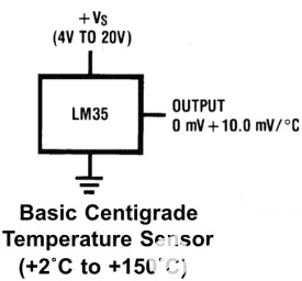
在本教程中,我们将使用 PIC 微控制器和 LM35 温度传感器制作数字温度计。在本项目中,我们将使用 LM35 检测温度并将其显示在 16x2 LCD 上。LM35 温度传感器准确且成本低廉,无需任何外部校准。输出电压与摄氏温标成正比,每°C变化10mV。
所需材料
图片套件 3
LM35 温度传感器
16 * 2液晶显示器
PIC16F877A 集成电路
40 - 引脚 IC 支架
性能板
20 MHz 晶体 OSC
内螺纹和外螺纹伯格斯图销
33pf 电容器 - 2 个电容、100uf 和 10uf 电容。
680 欧姆、220 欧姆、10K 和 560 欧姆电阻器
电位器 10k
任何颜色的发光二极管
1 焊接套件
集成电路 7805
12V 适配器
连接线
面包板
LM35 温度传感器:
LM35 温度传感器具有零失调电压,这意味着在 0°C 时输出将为 0V。它可以处理的最大电压为1.5V,这意味着它可以检测150°C(1.5V / 10mV)的最高温度。
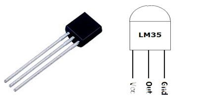
| 引脚编号 | 功能 | 名字 |
| 1 | 电源电压;5V (+35V 至 -2V) | Vcc |
| 2 | 输出电压(+6V至-1V) | 输出 |
| 3 | 接地 (0V) | 地 |
我们已经将LM35与许多其他微控制器一起使用来测量温度:
正如我们已经说过的,LM35 提供模拟输出,因此首先我们需要使用 PIC 微控制器读取该模拟值,然后我们将使用 ADC(模数转换)将它们转换为数字值。因此,在进一步讨论之前,我们将学习PIC微控制器中的ADC。
PIC 微控制器 PIC16F877A 中的 ADC:
有许多类型的ADC可用,每种都有自己的速度和分辨率。最常见的ADC类型是闪存、逐次逼近和Σ-Δ。PIC16F877A中使用的ADC类型简称为逐次逼近型ADC或SAR。因此,在开始使用SAR ADC之前,让我们先了解一下它。
逐次逼近型 ADC:SAR ADC在比较器和一些逻辑对话的帮助下工作。这种类型的ADC使用基准电压(可变的),并使用比较器将输入电压与基准电压进行比较,并从最高有效位(MSB)中保存差值(数字输出)。比较的速度取决于PIC运行的时钟频率(Fosc)。
现在我们了解了ADC的一些基础知识,让我们打开数据手册,了解如何在PIC16F877A MCU上使用ADC。我们使用的PIC具有10位8通道ADC。这意味着我们的ADC的输出值将为0-1024(2^10),并且我们的MCU上有8个引脚(通道)可以读取模拟电压。值 1024 由 2^10 获得,因为我们的 ADC 是 10 位。数据表中提到了可以读取模拟电压的八个引脚。让我们看看下面的图片。
模拟通道 AN0 到 AN7 已为您突出显示。只有这些引脚才能读取模拟电压。因此,在读取输入电压之前,我们必须在代码中指定必须使用哪个通道来读取输入电压。在本教程中,我们将使用带有电位计的通道4来读取该通道的模拟电压。
A/D 模块有四个寄存器,必须配置为从输入引脚读取数据。这些寄存器是:
• A/D 结果高寄存器 (ADRESH)
• A/D 结果低寄存器 (ADRESL)
• A/D 控制寄存器 0 (ADCON0)
• 模数控制寄存器 1 (ADCON1)
代码和说明
最后给出了使用LM35和PIC微控制器的数字温度计的完整代码。该代码是用注释行自我解释的,只涉及将LCD与PIC微控制器连接的概念,以及在PIC微控制器中使用ADC模块的概念,我们已经在之前的PIC微控制器学习教程中介绍过。
在这里,我们仅显示从LM35读取模拟输出电压然后将其转换为温度值的计算。因此,这里我们将LM35的ADC值转换为电压,然后将电压值转换为温度。因此,在获得值后,我们将每个字符分开以显示在LCD上。
adc = (ADC_Read(4)); // Reading ADC values
volt = adc*4.88281; // Convert it into the voltage
temp=volt/10.0; // Getting the temperature values
temp1 = temp*100;
c1 = (temp1/1000)%10;
c2 = (temp1/100)%10;
c3 = (temp1/10)%10;
c4 = (temp1/1)%10;
现在在下面的代码中,设置LCD光标,然后打印输出值
Lcd_Clear();
Lcd_Set_Cursor(1,3);
Lcd_Print_String("Temperature");
Lcd_Set_Cursor(2,5);
Lcd_Print_Char(c1+'0');
Lcd_Print_Char(c2+'0');
Lcd_Print_String(".");
Lcd_Print_Char(c3+'0');
Lcd_Print_Char(c4+'0');
Lcd_Print_Char(0xDF);
Lcd_Print_String("C");
__delay_ms(3000);
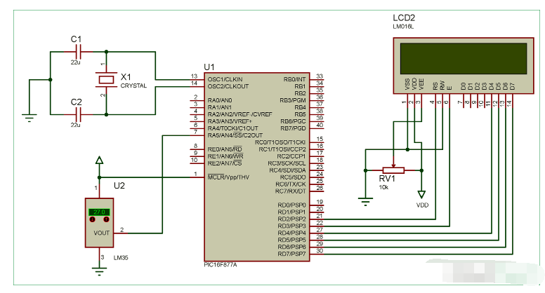
数字温度计的工作原理
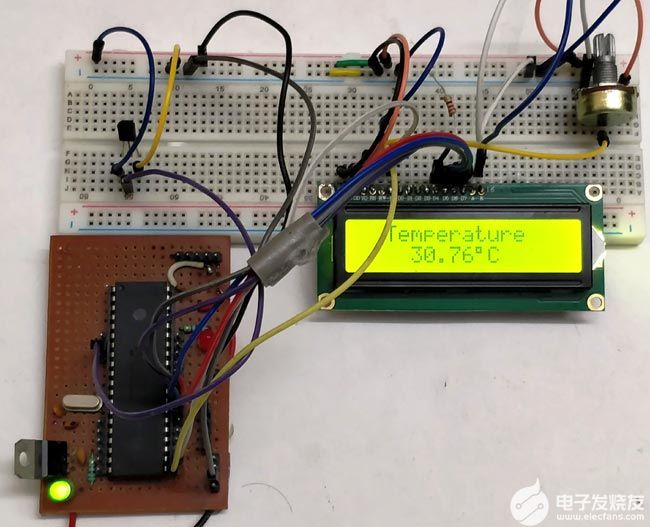
将代码上传到PIC微控制器后,使用12v适配器为电路上电。LM35 温度传感器的模拟输出被馈送到 PIC 控制器的模拟输入通道。随着温度的升高,ADC值也会增加。该ADC值通过乘以4.88281进一步转换为电压。然后将电压值转换为相应的字符,以将其显示到16 * 2 LCD中。
#define _XTAL_FREQ 20000000
#define RS RD2
#define EN RD3
#define D4 RD4
#define D5 RD5
#define D6 RD6
#define D7 RD7
#include
#pragma config FOSC = HS // Oscillator Selection bits (HS oscillator)
#pragma config WDTE = OFF // Watchdog Timer Enable bit (WDT disabled)
#pragma config PWRTE = ON // Power-up Timer Enable bit (PWRT enabled)
#pragma config BOREN = ON // Brown-out Reset Enable bit (BOR enabled)
#pragma config LVP = OFF // Low-Voltage (Single-Supply) In-Circuit Serial Programming Enable bit (RB3 is digital I/O, HV on MCLR must be used for programming)
#pragma config CPD = OFF // Data EEPROM Memory Code Protection bit (Data EEPROM code protection off)
#pragma config WRT = OFF // Flash Program Memory Write Enable bits (Write protection off; all program memory may be written to by EECON control)
#pragma config CP = OFF // Flash Program Memory Code Protection bit (Code protection off)
void ADC_Initialize()
{
ADCON0 = 0b01000001; //ADC ON and Fosc/16 is selected
ADCON1 = 0b11000000; // Internal reference voltage is selected
}
unsigned int ADC_Read(unsigned char channel)
{
ADCON0 &= 0x11000101; //Clearing the Channel Selection Bits
ADCON0 |= channel<<3; //Setting the required Bits
__delay_ms(2); //Acquisition time to charge hold capacitor
GO_nDONE = 1; //Initializes A/D Conversion
while(GO_nDONE); //Wait for A/D Conversion to complete
return ((ADRESH<<8)+ADRESL); //Returns Result
}
//LCD Functions Developed by Circuit Digest.
void Lcd_SetBit(char data_bit) //Based on the Hex value Set the Bits of the Data Lines
{
if(data_bit& 1)
D4 = 1;
else
D4 = 0;
if(data_bit& 2)
D5 = 1;
else
D5 = 0;
if(data_bit& 4)
D6 = 1;
else
D6 = 0;
if(data_bit& 8)
D7 = 1;
else
D7 = 0;
}
void Lcd_Cmd(char a)
{
RS = 0;
Lcd_SetBit(a); //Incoming Hex value
EN = 1;
__delay_ms(4);
EN = 0;
}
Lcd_Clear()
{
Lcd_Cmd(0); //Clear the LCD
Lcd_Cmd(1); //Move the curser to first position
}
void Lcd_Set_Cursor(char a, char b)
{
char temp,z,y;
if(a== 1)
{
temp = 0x80 + b - 1; //80H is used to move the curser
z = temp>>4; //Lower 8-bits
y = temp & 0x0F; //Upper 8-bits
Lcd_Cmd(z); //Set Row
Lcd_Cmd(y); //Set Column
}
else if(a== 2)
{
temp = 0xC0 + b - 1;
z = temp>>4; //Lower 8-bits
y = temp & 0x0F; //Upper 8-bits
Lcd_Cmd(z); //Set Row
Lcd_Cmd(y); //Set Column
}
}
void Lcd_Start()
{
Lcd_SetBit(0x00);
for(int i=1065244; i<=0; i--) NOP();
Lcd_Cmd(0x03);
__delay_ms(5);
Lcd_Cmd(0x03);
__delay_ms(11);
Lcd_Cmd(0x03);
Lcd_Cmd(0x02); //02H is used for Return home -> Clears the RAM and initializes the LCD
Lcd_Cmd(0x02); //02H is used for Return home -> Clears the RAM and initializes the LCD
Lcd_Cmd(0x08); //Select Row 1
Lcd_Cmd(0x00); //Clear Row 1 Display
Lcd_Cmd(0x0C); //Select Row 2
Lcd_Cmd(0x00); //Clear Row 2 Display
Lcd_Cmd(0x06);
}
void Lcd_Print_Char(char data) //Send 8-bits through 4-bit mode
{
char Lower_Nibble,Upper_Nibble;
Lower_Nibble = data&0x0F;
Upper_Nibble = data&0xF0;
RS = 1; // => RS = 1
Lcd_SetBit(Upper_Nibble>>4); //Send upper half by shifting by 4
EN = 1;
for(int i=2130483; i<=0; i--) NOP();
EN = 0;
Lcd_SetBit(Lower_Nibble); //Send Lower half
EN = 1;
for(int i=2130483; i<=0; i--) NOP();
EN = 0;
}
void Lcd_Print_String(char *a)
{
int i;
for(i=0;a[i]!='';i++)
Lcd_Print_Char(a[i]); //Split the string using pointers and call the Char function
}
int main()
{
float adc;
float volt, temp;
int c1, c2, c3, c4, temp1;
ADC_Initialize();
unsigned int a;
TRISD = 0x00;
Lcd_Start();
while(1)
{
adc = (ADC_Read(4)); // Reading ADC values
volt = adc*4.88281; // Convert it into the voltage
temp=volt/10.0; // Getting the temperature values
temp1 = temp*100;
c1 = (temp1/1000)%10;
c2 = (temp1/100)%10;
c3 = (temp1/10)%10;
c4 = (temp1/1)%10;
Lcd_Clear();
Lcd_Set_Cursor(1,3);
Lcd_Print_String("Temperature");
Lcd_Set_Cursor(2,5);
Lcd_Print_Char(c1+'0');
Lcd_Print_Char(c2+'0');
Lcd_Print_String(".");
Lcd_Print_Char(c3+'0');
Lcd_Print_Char(c4+'0');
Lcd_Print_Char(0xDF);
Lcd_Print_String("C");
__delay_ms(3000);
}
return 0;
}
-
LM35温度传感器应用及特性2010-01-16 14014
-
基于微控制器的数字温度计2022-07-27 1177
-
如何利用DS18B20传感器通过PIC微控制器获得温度2022-11-16 4892
-
如何使用8051微控制器构建一个简单的数字温度计2022-11-21 5133
-
基于LM35和LM3914的电子温度计2011-09-16 16463
-
LM35温度传感器2012-08-14 3308
-
使用LM35温度传感器和ATTiny13微控制器控制风扇的教程2022-07-21 1819
-
急求基于LM35与TC7107的数字温度计,可报警2022-09-11 94126
-
采用LM35和ICL7107构成的数字温度计电路图2009-07-16 3496
-
如何制作数字温度计2009-08-21 7455
-
温度传感器 LM35介绍2009-12-02 30408
-
基于LM35温度传感器的高精度恒温控制系统2018-01-31 11921
-
LM35与ICL7107构成的温度计,LM35 thermometer2018-09-20 2887
-
物联网课程系列:制作一个可爱的鲨鱼温度计2020-12-26 1762
-
如何使用Arduino和LM35传感器制作温度计2022-11-24 1774
全部0条评论

快来发表一下你的评论吧 !
