

BGP实验拓扑及说明
描述
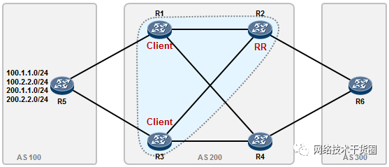
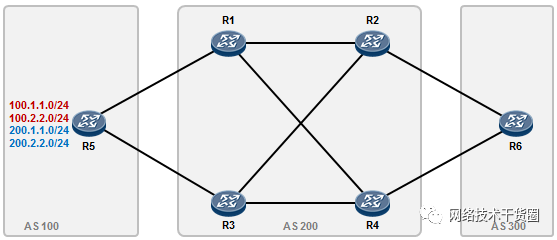
实验拓扑及说明
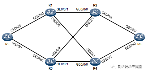
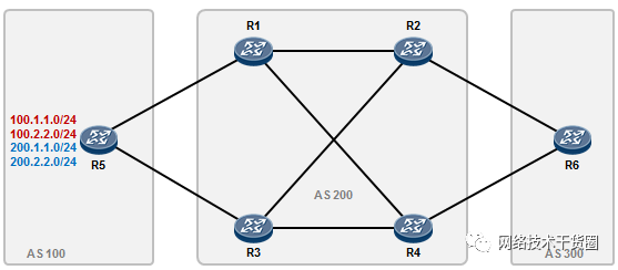
设备编号及互联线路如图所示;所有设备的互联地址段采用10.1.xy.0/24,其中xy为设备编号,x为编号较小的设备,y为编号较大的设备。例如R2及R3之间的直连链路,网段为10.1.23.0/24,这条链路上R2的接口IP地址为10.1.23.2/24,R3的接口IP地址为10.1.23.3/24。所有设备配置loopback0接口,ip地址为x.x.x.x/32,其中x为设备编号;
实验需求一(完成基础配置)
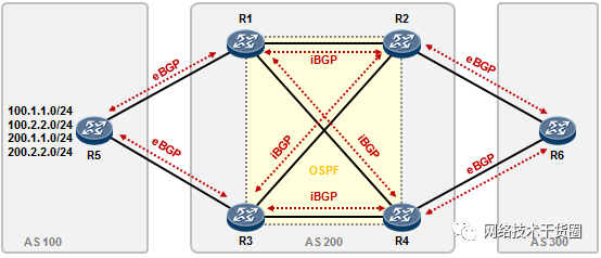
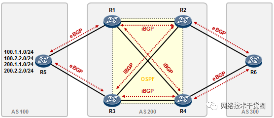
BGP邻居关系如图所示;除了图中标记的BGP邻居关系外不得建立其他的BGP连接。
R1、R2、R3、R4运行OSPF,注意OSPF域的范围;四台路由器都将自己的Loopback0口宣告进OSPF,AS之间的链路不宣告进OSPF。
eBGP邻居关系采用直连接口建立;iBGP邻居关系采用loopback0口建立;
在R5上开设Loopback1至Loopback4,IP地址分别为100.1.1.0/24、100.2.2.0/24、200.1.1.0/24、200.2.2.0/24。
R1的配置如下:
[R1] interface GigabitEthernet0/0/0
[R1-GigabitEthernet0/0/0] ip address 10.1.15.1 255.255.255.0
[R1] interface GigabitEthernet0/0/1
[R1-GigabitEthernet0/0/1] ip address 10.1.12.1 255.255.255.0
[R1] interface GigabitEthernet0/0/2
[R1-GigabitEthernet0/0/2] ip address 10.1.14.1 255.255.255.0
[R1] interface LoopBack0
[R1-LoopBack0] ip address 1.1.1.1 255.255.255.255

[R1] ospf 1 router-id 1.1.1.1
[R1-ospf-1] area 0.0.0.0
[R1-ospf-1-0.0.0.0] network 1.1.1.1 0.0.0.0
[R1-ospf-1-0.0.0.0] network 10.1.12.1 0.0.0.0
[R1-ospf-1-0.0.0.0] network 10.1.14.1 0.0.0.0

[R1] bgp 200
[R1-bgp] router-id 1.1.1.1
[R1-bgp] peer 2.2.2.2 as-number 200
[R1-bgp] peer 2.2.2.2 connect-interface LoopBack0
[R1-bgp] peer 2.2.2.2 next-hop-local
[R1-bgp] peer 4.4.4.4 as-number 200
[R1-bgp] peer 4.4.4.4 connect-interface LoopBack0
[R1-bgp] peer 4.4.4.4 next-hop-local
[R1-bgp] peer 10.1.15.5 as-number 100
R2的配置如下:
[R2] interface GigabitEthernet0/0/0
[R2-GigabitEthernet0/0/0] ip address 10.1.12.2 255.255.255.0
[R2] interface GigabitEthernet0/0/1
[R2-GigabitEthernet0/0/1] ip address 10.1.23.2 255.255.255.0
[R2] interface GigabitEthernet0/0/2
[R2-GigabitEthernet0/0/2] ip address 10.1.26.2 255.255.255.0
[R2] interface LoopBack0
[R2-LoopBack0] ip address 2.2.2.2 255.255.255.255

[R2] ospf 1 router-id 2.2.2.2
[R2-ospf-1] area 0.0.0.0
[R2-ospf-1-0.0.0.0] network 2.2.2.2 0.0.0.0
[R2-ospf-1-0.0.0.0] network 10.1.12.2 0.0.0.0
[R2-ospf-1-0.0.0.0] network 10.1.23.2 0.0.0.0

[R2] bgp 200
[R2-bgp] router-id 2.2.2.2
[R2-bgp] peer 1.1.1.1 as-number 200
[R2-bgp] peer 1.1.1.1 connect-interface LoopBack0
[R2-bgp] peer 3.3.3.3 as-number 200
[R2-bgp] peer 3.3.3.3 connect-interface LoopBack0
[R2-bgp] peer 10.1.26.6 as-number 300
R3的配置如下:
[R3] interface GigabitEthernet0/0/0
[R3-GigabitEthernet0/0/0] ip address 10.1.35.3 255.255.255.0
[R3] interface GigabitEthernet0/0/1
[R3-GigabitEthernet0/0/1] ip address 10.1.34.3 255.255.255.0
[R3] interface GigabitEthernet0/0/2
[R3-GigabitEthernet0/0/2] ip address 10.1.23.3 255.255.255.0
[R3] interface LoopBack0
[R3-GigabitEthernet0/0/0] ip address 3.3.3.3 255.255.255.255

[R3] ospf 1 router-id 3.3.3.3
[R3-ospf-1] area 0.0.0.0
[R3-ospf-1-0.0.0.0] network 3.3.3.3 0.0.0.0
[R3-ospf-1-0.0.0.0] network 10.1.23.3 0.0.0.0
[R3-ospf-1-0.0.0.0] network 10.1.34.3 0.0.0.0

[R3] bgp 200
[R3-bgp] router-id 3.3.3.3
[R3-bgp] peer 2.2.2.2 as-number 200
[R3-bgp] peer 2.2.2.2 connect-interface LoopBack0
[R3-bgp] peer 2.2.2.2 next-hop-local
[R3-bgp] peer 4.4.4.4 as-number 200
[R3-bgp] peer 4.4.4.4 connect-interface LoopBack0
[R3-bgp] peer 4.4.4.4 next-hop-local
[R3-bgp] peer 10.1.35.5 as-number 100
R4的配置如下:
[R4] interface GigabitEthernet0/0/0
[R4-GigabitEthernet0/0/0] ip address 10.1.34.4 255.255.255.0
[R4] interface GigabitEthernet0/0/1
[R4-GigabitEthernet0/0/1] ip address 10.1.14.4 255.255.255.0
[R4] interface GigabitEthernet0/0/2
[R4-GigabitEthernet0/0/2] ip address 10.1.46.4 255.255.255.0
[R4] interface LoopBack0
[R4-LoopBack0] ip address 4.4.4.4 255.255.255.255

[R4] ospf 1 router-id 4.4.4.4
[R4-ospf-1] area 0.0.0.0
[R4-ospf-1-0.0.0.0] network 4.4.4.4 0.0.0.0
[R4-ospf-1-0.0.0.0] network 10.1.14.4 0.0.0.0
[R4-ospf-1-0.0.0.0] network 10.1.34.4 0.0.0.0

[R4] bgp 200
[R4-bgp] router-id 4.4.4.4
[R4-bgp] peer 1.1.1.1 as-number 200
[R4-bgp] peer 1.1.1.1 connect-interface LoopBack0
[R4-bgp] peer 3.3.3.3 as-number 200
[R4-bgp] peer 3.3.3.3 connect-interface LoopBack0
[R4-bgp] peer 10.1.46.6 as-number 300
R5的配置如下:
[R5] interface GigabitEthernet0/0/0
[R5-GigabitEthernet0/0/0] ip address 10.1.15.5 255.255.255.0
[R5] interface GigabitEthernet0/0/1
[R5-GigabitEthernet0/0/1] ip address 10.1.35.5 255.255.255.0
[R5] interface LoopBack0
[R5-LoopBack0] ip address 5.5.5.5 255.255.255.255
[R5] interface LoopBack1
[R5-LoopBack1] ip address 100.1.1.1 255.255.255.0
[R5] interface LoopBack2
[R5-LoopBack2] ip address 100.2.2.2 255.255.255.0
[R5] interface LoopBack3
[R5-LoopBack3] ip address 200.1.1.1 255.255.255.0
[R5] interface LoopBack4
[R5-LoopBack4] ip address 200.2.2.2 255.255.255.0
[R5] bgp 100
[R5-bgp] router-id 5.5.5.5
[R5-bgp] peer 10.1.15.1 as-number 200
[R5-bgp] peer 10.1.35.3 as-number 200
[R5-bgp] network 100.1.1.0 24
[R5-bgp] network 100.2.2.0 24
[R5-bgp] network 200.1.1.0 24
[R5-bgp] network 200.2.2.0 24
R6的配置如下:
[R6] interface GigabitEthernet0/0/0
[R6-GigabitEthernet0/0/0] ip address 10.1.26.6 255.255.255.0
[R6] interface GigabitEthernet0/0/1
[R6-GigabitEthernet0/0/1] ip address 10.1.46.6 255.255.255.0
[R6] interface LoopBack0
[R6-LoopBack0] ip address 6.6.6.6 255.255.255.255

[R6] bgp 300
[R6-bgp] router-id 6.6.6.6
[R6-bgp] peer 10.1.26.2 as-number 200
[R6-bgp] peer 10.1.46.4 as-number 200
在R1上查看BGP邻居关系:
[R1] display bgp peer
BGP local router ID : 1.1.1.1
Local AS number : 200
Total number of peers : 3 Peers in established state : 3
Peer V AS MsgRcvd MsgSent OutQ Up/Down State PrefRcv
2.2.2.2 4 200 10 12 0 0044 Established 0
4.4.4.4 4 200 6 8 0 0028 Established 0
10.1.15.5 4 100 7 6 0 0050 Established 4
其他路由器的BGP邻居请做相应查看,确保所有的BGP邻居关系都正确的建立。
实验需求二
- R1访问100网段及200网段的流量直接送到R5,当R1与R5之间的链路发生故障时,R1访问这两个子网的流量自动切换到R2-R3-R5。当R1与R5及R2之间的链路均发生故障时,R1访问这两个子网的流量自动切换到R4-R3-R5。
- R3访问100网段及200网段的流量直接送到R5,当R3与R5之间的链路发生故障时,R3访问这两个子网的流量自动切换到R4-R1-R5。当R3与R5及R4之间的链路均发生故障时,R1访问这两个子网的流量自动切换到R2-R1-R5。
- R2访问100网段的流量优先走R1,当R1发生故障,或者R1-R2之间的互联线路DOWN掉时,流量切换到R3。
- R2访问200网段的流量优先走R3,当R3发生故障,或者R3-R2之间的互联线路DOWN掉时,流量切换到R1。
- R4访问100网段的流量优先走R1,当R1发生故障,或者R1-R4之间的互联线路DOWN掉时,流量切换到R3。
- R4访问200网段的流量优先走R3,当R3发生故障,或者R3-R4之间的互联线路DOWN掉时,流量切换到R1。
- 注意,实验过程中只需满足以上需求即可,无需考虑往返路径一致或者ping通的问题。
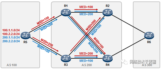
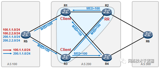
实际上满足上述需求的方法有很多,毕竟BGP的路径属性非常丰富,路由策略工具也很多。这里我们考虑在R5上部署策略,采用MED属性来操控路由,如此一来MED值除了影响R1、R3的路由优选,还将进一步的影响路由在AS200内的优选,大体思路如下:
R5的配置新增如下:
#写两个IP前缀列表,分别匹配100及200路由:
[R5] ip ip-prefix 1 index 10 permit 100.1.1.0 24
[R5] ip ip-prefix 1 index 20 permit 100.2.2.0 24
[R5] ip ip-prefix 2 index 10 permit 200.1.1.0 24
[R5] ip ip-prefix 2 index 20 permit 200.2.2.0 24

#写两个route-policy,分别对100及200的路由设置MED属性值:
[R5] route-policy toR1 permit node 10
[R5-route-policy] if-match ip-prefix 1
[R5-route-policy] apply cost 100
[R5] route-policy toR1 permit node 20
[R5-route-policy] if-match ip-prefix 2
[R5-route-policy] apply cost 200

[R5] route-policy toR3 permit node 10
[R5-route-policy] if-match ip-prefix 1
[R5-route-policy] apply cost 200
[R5] route-policy toR3 permit node 20
[R5-route-policy] if-match ip-prefix 2
[R5-route-policy] apply cost 100

#在BGP配置视图下,将路由策略应用在R1及R3的出站方向:
[R5] bgp 100
[R5-bgp] peer 10.1.15.1 route-policy toR1 export
[R5-bgp] peer 10.1.35.3 route-policy toR3 export
完成上述配置后在网络正常情况下,R1、R3访问100网段及200网段的流量已经满足需求,例如R1的BGP表如下:
 display bgp routing-table
BGP Local router ID is 1.1.1.1
Status codes: * - valid, > - best, d - damped,
h - history, i - internal, s - suppressed, S - Stale
Origin : i - IGP, e - EGP, ? - incomplete
Total Number of Routes: 4
Network NextHop MED LocPrf PrefVal Path/Ogn
*> 100.1.1.0/24 10.1.15.5 0 0 100i
*> 100.2.2.0/24 10.1.15.5 0 0 100i
*> 200.1.1.0 10.1.15.5 0 0 100i
*> 200.2.2.0 10.1.15.5 0 0 100i
R2及R4访问100及200网络也满足需求,例如R2的BGP表:
display bgp routing-table
BGP Local router ID is 2.2.2.2
Status codes: * - valid, > - best, d - damped,
h - history, i - internal, s - suppressed, S - Stale
Origin : i - IGP, e - EGP, ? - incomplete
Total Number of Routes: 8
Network NextHop MED LocPrf PrefVal Path/Ogn
*>i 100.1.1.0/24 1.1.1.1 100 100 0 100i
* i 3.3.3.3 200 100 0 100i
*>i 100.2.2.0/24 1.1.1.1 100 100 0 100i
* i 3.3.3.3 200 100 0 100i
*>i 200.1.1.0 3.3.3.3 100 100 0 100i
* i 1.1.1.1 200 100 0 100i
*>i 200.2.2.0 3.3.3.3 100 100 0 100i
* i 1.1.1.1 200 100 0 100i
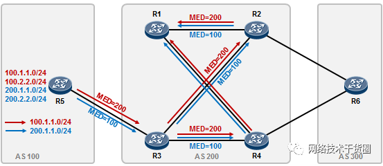
但是R1与R5之间的连线一旦断开,R1将丢失到达这两个子网的路由,这是因为R2及R4不会将自己从R3学习到的路由再传递给R1 -- IBGP水平分割规则使然。R3同样存在类似的问题。
解决的办法是,在AS200内构建路由反射簇,将R2设置为RR,R1及R3是它的Client;将R4也设置为RR,R1及R3是它的Client。
R2的配置增加如下:
[R2] bgp 200
[R2-bgp] peer 1.1.1.1 reflect-client
[R2-bgp] peer 3.3.3.3 reflect-client
R4的配置增如如下:
[R4] bgp 200
[R4-bgp] peer 1.1.1.1 reflect-client
[R4-bgp] peer 3.3.3.3 reflect-client
完成上述配置后,R1及R3的选路似乎出现了点问题,拿R1来说,关于100网段的路由在其BGP表中自然只有一条路径那就是来自R5的。但是200网段的两路由,BGP表里却各有三条路径:
display bgp routing-table
BGP Local router ID is 1.1.1.1
Status codes: * - valid, > - best, d - damped,
h - history, i - internal, s - suppressed, S - Stale
Origin : i - IGP, e - EGP, ? - incomplete
Total Number of Routes: 8
Network NextHop MED LocPrf PrefVal Path/Ogn
*> 100.1.1.0/24 10.1.15.5 100 0 100i
*> 100.2.2.0/24 10.1.15.5 100 0 100i
*>i 200.1.1.0 3.3.3.3 100 100 0 100i
* i 3.3.3.3 100 100 0 100i
* 10.1.15.5 200 0 100i
*>i 200.2.2.0 3.3.3.3 100 100 0 100i
* i 3.3.3.3 100 100 0 100i
* 10.1.15.5 200 0 100i
三条路径其中一条是更新自R5,另外两条分别更新自R2和R4(他们将自己从R3学习到的200路由反射给了R1):
而R1关于200.1.1.0/24及200.2.2.0/24最终优选了来自R2的更新(这个更新实际上是R3将路由传递给R2,R2再更新给R1的)这个选路就不符合需求了,那么如何保证在网络正常的情况下,R1关于100及200的路由都优选来自R5的更新,当R1丢失了与R5的连接,则优选来自R2的更新呢?
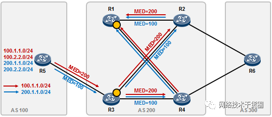
这里可以利用preferred-value这个属性,在R1及R3上部署。在R1上部署时,将R5传递过来的100及200路由的preferred-value设置为100。在R3上部署时,将R5传递过来的100及200路由的preferred-value设置为100。
R1的配置如下:
[R1] ip ip-prefix 1 index 10 permit 100.1.1.0 24
[R1] ip ip-prefix 1 index 20 permit 100.2.2.0 24
[R1] ip ip-prefix 2 index 10 permit 200.1.1.0 24
[R1] ip ip-prefix 2 index 20 permit 200.2.2.0 24
[R1] route-policy For_R5 permit node 10
[R1-route-policy] if-match ip-prefix 1
[R1-route-policy] apply preferred-value 100
[R1] route-policy For_R5 permit node 20
[R1-route-policy] if-match ip-prefix 2
[R1-route-policy] apply preferred-value 100

[R1] bgp 200
[R1-route-policy] peer 10.1.15.5 route-policy For_R5 import
R3的配置如下:
[R3] ip ip-prefix 1 index 10 permit 100.1.1.0 24
[R3] ip ip-prefix 1 index 20 permit 100.2.2.0 24
[R3] ip ip-prefix 2 index 10 permit 200.1.1.0 24
[R3] ip ip-prefix 2 index 20 permit 200.2.2.0 24
[R3] route-policy For_R5 permit node 10
[R3-route-policy] if-match ip-prefix 1
[R3-route-policy] apply preferred-value 100
[R3] route-policy For_R5 permit node 20
[R3-route-policy] if-match ip-prefix 2
[R3-route-policy] apply preferred-value 100
[R3] bgp 200
[R3-bgp] peer 10.1.35.5 route-policy For_R5 import
完成上述配置后,看一下R1的BGP表:
[R1] display bgp routing-table
BGP Local router ID is 1.1.1.1
Status codes: * - valid, > - best, d - damped,
h - history, i - internal, s - suppressed, S - Stale
Origin : i - IGP, e - EGP, ? - incomplete
Total Number of Routes: 8
Network NextHop MED LocPr  PrefVal Path/Ogn
*> 100.1.1.0/24 10.1.15.5 100 100 100i
*> 100.2.2.0/24 10.1.15.5 100 100 100i
*> 200.1.1.0 10.1.15.5 200 100 100i
* i 3.3.3.3 100 100 0 100i
* i 3.3.3.3 100 100 0 100i
*> 200.2.2.0 10.1.15.5 200 100 100i
* i 3.3.3.3 100 100 0 100i
* i 3.3.3.3 100 100 0 100i
200的路由R1优选了来自R5的更新。同样的,R3也会优选来自R5的更新。
现在切断R1与R5之间的连线:
R1的BGP表变成了这样:
[R1]display bgp routing-table
BGP Local router ID is 1.1.1.1
Status codes: * - valid, > - best, d - damped,
h - history, i - internal, s - suppressed, S - Stale
Origin : i - IGP, e - EGP, ? - incomplete
Total Number of Routes: 8
Network NextHop MED LocPrf PrefVal Path/Ogn
*>i 100.1.1.0/24 3.3.3.3 200 100 0 100i
* i 3.3.3.3 200 100 0 100i
*>i 100.2.2.0/24 3.3.3.3 200 100 0 100i
* i 3.3.3.3 200 100 0 100i
*>i 200.1.1.0 3.3.3.3 100 100 0 100i
* i 3.3.3.3 100 100 0 100i
*>i 200.2.2.0 3.3.3.3 100 100 0 100i
* i 3.3.3.3 100 100 0 100i
R1上100及200的路由各有2条路径,R1会优选来自R2的BGP路由更新,这是因为R2的peeraddress要更小。虽然如此,但实际上R1去往目标网段的流量是在R2和R4上进行负载分担的,这是因为BGP路由的下一跳是3.3.3.3,而R1的3.3.3.3路由通过OSPF从R2及R4都可达并且是等代价的路径,所以这与我们的需求就不符了,需求是要让流量走R2,只当R2也挂掉的时候才走R4。
[R1]display ip routing-table protocol bgp
Route Flags: R - relay, D - download to fib
------------------------------------------------------------------------------
Public routing table : BGP
Destinations : 4 Routes : 4
BGP routing table status :
Destinations : 4 Routes : 4
Destination/Mask Proto  Pre Cost  Flags NextHop Interface
100.1.1.0/24 IBGP 255 200 RD 3.3.3.3 GigabitEthernet0/0/1
IBGP 255 200 RD 3.3.3.3 GigabitEthernet0/0/2
100.2.2.0/24 IBGP  255 200 RD 3.3.3.3 GigabitEthernet0/0/1
IBGP  255 200 RD 3.3.3.3 GigabitEthernet0/0/2
200.1.1.0/24 IBGP 255 100 RD 3.3.3.3 GigabitEthernet0/0/1
IBGP 255 100 RD 3.3.3.3 GigabitEthernet0/0/2
200.2.2.0/24 IBGP  255 100 RD 3.3.3.3 GigabitEthernet0/0/1
IBGP  255 100 RD 3.3.3.3 GigabitEthernet0/0/2
BGP routing table status :
Destinations : 0 Routes : 0
如何解决这个问题呢?很简单,将如下图所示的接口的OSPF COST值调大即可:
R1:
[R1] interface GigabitEthernet 0/0/2
[R1-GigabitEthernet 0/0/2] ospf cost 999
R3:
[R3] interface GigabitEthernet 0/0/2
[R3-GigabitEthernet 0/0/2] ospf cost 999
这么一来,对于R1而言(R3也是类似的道理),在R1-R5之间线路DOWN掉时,其关于100及200的路由将优选来自R2的路由更新,并且数据转发时将始终使用R2-R3-R5这条路径。
[R1] display ip routing-table protocol bgp
Route Flags: R - relay, D - download to fib
------------------------------------------------------------------------------
Public routing table : BGP
Destinations : 4 Routes : 4
BGP routing table status :
Destinations : 4 Routes : 4
Destination/Mask Proto  Pre Cost  Flags NextHop Interface
100.1.1.0/24 IBGP 255 200 RD 3.3.3.3 GigabitEthernet0/0/1
100.2.2.0/24 IBGP  255 200 RD 3.3.3.3 GigabitEthernet0/0/1
200.1.1.0/24 IBGP 255 100 RD 3.3.3.3 GigabitEthernet0/0/1
200.2.2.0/24 IBGP  255 100 RD 3.3.3.3 GigabitEthernet0/0/1
BGP routing table status :
Destinations : 0 Routes : 0
实验需求三
在完成上述配置后,要求在R6上部署策略,使得R6去往100网段主走R2,R4为备份路径;去往200网段主走R4,R2为备份路径。
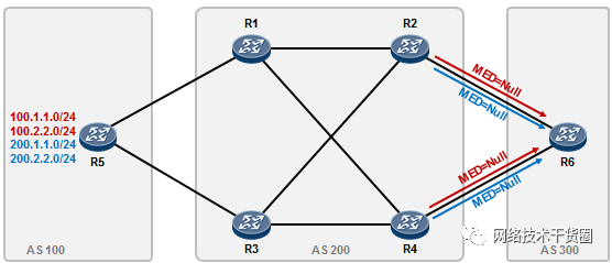
在完成上述配置后R2及R4都会向R6通告100及200的路由,并且路由的MED值均为空,也就是说,R5在发布路由时通过策略为路由携带的MED属性值不会随着路由传递给AS300。
对于这四条目标路由,R6均优选自R2的更新,这是因为R2的RouterID比R5要小,通过如下的输出可以验证:
display bgp routing-table 100.1.1.0
BGP local router ID : 6.6.6.6
Local AS number : 300
Paths: 2 available, 1 best, 1 select
BGP routing table entry information of 100.1.1.0/24:
From: 10.1.26.2 (2.2.2.2)
Route Duration: 00h17m37s
Direct Out-interface: GigabitEthernet0/0/0
Original nexthop: 10.1.26.2
Qos information : 0x0
AS-path 200 100, origin igp, pref-val 0, valid, external, best, select, active,
pre 255
Advertised to such 2 peers:
10.1.26.2
10.1.46.4
BGP routing table entry information of 100.1.1.0/24:
From: 10.1.46.4 (4.4.4.4)
Route Duration: 00h17m37s
Direct Out-interface: GigabitEthernet0/0/1
Original nexthop: 10.1.46.4
Qos information : 0x0
AS-path 200 100, origin igp, pref-val 0, valid, external, pre 255, not preferred
for router ID
Not advertised to any peer yet
现在我们在R6上部署策略来满足需求,方法有不少,这里我们使用Local_preference属性。
[R6] ip ip-prefix 1 index 10 permit 100.1.1.0 24
[R6] ip ip-prefix 1 index 20 permit 100.2.2.0 24
[R6] ip ip-prefix 2 index 10 permit 200.1.1.0 24
[R6] ip ip-prefix 2 index 20 permit 200.2.2.0 24
[R6] route-policy For_R2 permit node 10
[R6-route-policy] if-match ip-prefix 1
[R6-route-policy] apply local-preference 200
[R6] route-policy For_R2 permit node 20
[R6-route-policy] if-match ip-prefix 2
[R6-route-policy] apply local-preference 100

[R6] route-policy For_R4 permit node 10
[R6-route-policy] if-match ip-prefix 1
[R6-route-policy] apply local-preference 100
[R6] route-policy For_R4 permit node 20
[R6-route-policy] if-match ip-prefix 2
[R6-route-policy] apply local-preference 200

[R6] bgp 300
[R6] peer 10.1.26.2 route-policy For_R2 import
[R6] peer 10.1.46.4 route-policy For_R4 import

[R6] display bgp routing-table
BGP Local router ID is 6.6.6.6
Status codes: * - valid, > - best, d - damped,
h - history, i - internal, s - suppressed, S - Stale
Origin : i - IGP, e - EGP, ? - incomplete
Total Number of Routes: 8
Network NextHop MED LocPrf PrefVal Path/Ogn
*> 100.1.1.0/24 10.1.26.2 200 0 200 100i
* 10.1.46.4 100 0 200 100i
*> 100.2.2.0/24 10.1.26.2 200 0 200 100i
* 10.1.46.4 100 0 200 100i
*> 200.1.1.0 10.1.46.4 200 0 200 100i
* 10.1.26.2 100 0 200 100i
*> 200.2.2.0 10.1.46.4 200 0 200 100i
* 10.1.26.2 100 0 200 100i
从上面的输出可以看出,关于100网段的两条路由,R6优选来自R2的更新;而200网段的两条路由,R6优选来自R4的更新。
实验需求四
在上述需求的基础上,AS200内的R1上有部分直连网段需要发布出来以便R5能够通过BGP学习到,新增一个Loopback接口,配置IP:11.11.11.11/32用于模拟直连网段(实际可能较多),通告进BGP。但是R6也就学习到了这些路由,在R6上完成相应的配置,使得它仅仅收到AS100的路由,对于始发于AS200的路由,R6将过滤掉。注意始发于AS200的路由多而杂,请在R6上采用适当的方式过滤掉这些路由。R1增补配置如下:
[R1] Interface loopback 11
[R1-LoopBack11] Ip address 11.11.11.11 32
[R1] bgp 200
[R1-bgp] network 11.11.11.11 32

[R6] display bgp routing-table
BGP Local router ID is 6.6.6.6
Status codes: * - valid, > - best, d - damped,
h - history, i - internal, s - suppressed, S - Stale
Origin : i - IGP, e - EGP, ? - incomplete
Total Number of Routes: 8
Network NextHop MED LocPrf PrefVal Path/Ogn
*> 11.11.11.11/32 10.1.26.2 0 200i
* 10.1.46.4 0 200i
*> 100.1.1.0/24 10.1.26.2 200 0 200 100i
* 10.1.46.4 100 0 200 100i
*> 100.2.2.0/24 10.1.26.2 200 0 200 100i
* 10.1.46.4 100 0 200 100i
*> 200.1.1.0 10.1.46.4 200 0 200 100i
* 10.1.26.2 100 0 200 100i
*> 200.2.2.0 10.1.46.4 200 0 200 100i
* 10.1.26.2 100 0 200 100i
R6已经学习到AS200的路由11.11.11.11/32了。由于现在无法知道也不可能知道AS200内路由的所有前缀,因此无法使用ACL或者前缀列表来抓取路由从而进一步的过滤。实现这个需求最简单的方法是采用基于AS_PATH的过滤,利用一个正则表达式来抓取200的AS号。
R6增加如下配置:
[R6] ip as-path-filter noAS200 deny ^200$  #抓取AS200,deny所匹配的路由
[R6] ip as-path-filter noAS200 permit .* #允许任意
[R6] bgp 300
[R6-bgp] peer 10.1.26.2 as-path-filter noAS200 import
[R6-bgp] peer 10.1.46.4 as-path-filter noAS200 import
完成上述配置后,R6将过滤掉所有始发于AS200的路由。
实验需求五
将实验需求三、四中的相关配置删除,将实验场景还原到满足需求二的情形。
现在要求通过在R2、R4上进行相关配置,使得R6去往100网段的流量主走R2,R4为备份;去往200网段的流量主走R4,R2为备。要求在R2、R4上不使用route-policy对R6做出站方向的策略。
利用“最长匹配原则”,可以很好的实现数据分流。如下图所示,在R2上部署路由汇总,将200网段的两条路由汇总成200.0.0.0/8,加上100网段的明细路由一并更新给R6;在R4上部署路由汇总,将100网段的路由汇总成100.0.0.0/8,加上200网段的明细路由一并更新给R6。
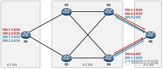
这么一来,在网络正常的情况下,R6去往100.1.1.0/24及100.2.2.0/24会走R2,当R2发生故障时,由于还有一条R4发送过来的100.0.0.0/8汇总路由,因此流量能够自动切换到R4。
R2的增补配置如下:
[R2] bgp 200
[R2-bgp] aggregate 200.0.0.0 8 as-set
R4的增补配置如下:
[R4] bgp 200
[R4-bgp] aggregate 100.0.0.0 8 as-set
注意,在R2及R4上部署路由汇总时,在这个场景中汇总命令不能加detail-suppressed而抑制明细,这是因为如果这里增加了该关键字,R2及R4将只发布汇总路由,而抑制明细,这会影响到前面的需求二。设想一下,如果R2的汇总命令中加了detail-suppressed关键字,那么R2将不再向R1及R3反射200网段的明细路由,在网络发生故障时,R2将失去作为备份路径的可能。
接下去,在R2上部署策略,将200网段的明细过滤掉不发给R6;在R4上部署策略,将100网段的明细过滤掉不发给R6:R2增补配置如下:
[R2] ip ip-prefix toR6 index 10 deny 200.0.0.0 8 greater-equal 24 less-equal 24
#上面这条前缀列表是匹配200开头、掩码是/24的路由
[R2] ip ip-prefix toR6 index 20 permit 0.0.0.0 0 less-equal 32
#上面这条前缀列表是匹配所有路由
[R2] bgp 200
[R2-bgp] peer 10.1.26.6 ip-prefix toR6 export
R4增补配置如下:
[R4] ip ip-prefix toR6 index 10 deny 100.0.0.0 8 greater-equal 24 less-equal 24
[R4] ip ip-prefix toR6 index 20 permit 0.0.0.0 0 less-equal 32
[R4] bgp 200
[R4-bgp] peer 10.1.46.6 ip-prefix toR6 export
display bgp routing-table
BGP Local router ID is 6.6.6.6
Status codes: * - valid, > - best, d - damped,
h - history, i - internal, s - suppressed, S - Stale
Origin : i - IGP, e - EGP, ? - incomplete
Total Number of Routes: 6
Network NextHop MED LocPrf PrefVal Path/Ogn
*> 100.0.0.0 10.1.46.4 0 200 100i
*> 100.1.1.0/24 10.1.26.2 0 200 100i
*> 100.2.2.0/24 10.1.26.2 0 200 100i
*> 200.0.0.0/8 10.1.26.2 0 200 100i
*> 200.1.1.0 10.1.46.4 0 200 100i
*> 200.2.2.0 10.1.46.4 0 200 100i
需求满足了,但是由于在R2、R4上部署了路由汇总,产生的汇总路由不仅传递给了R6,也传递给了R1及R3,而实际上,这两条汇总路由R1及R3并不需要,因此还需过滤掉。同样过滤的方法也很多。
R2的配置增补如下:
[R2] ip ip-prefix noAggregation index 10 deny 200.0.0.0 8
[R2] ip ip-prefix noAggregation index 20 permit 0.0.0.0 0 less-equal 32
[R2] bgp 200
[R2-bgp] peer 1.1.1.1 ip-prefix noAggregation export
[R2-bgp] peer 3.3.3.3 ip-prefix noAggregation export
R4的配置增补如下:
[R4] ip ip-prefix noAggregation index 10 deny 100.0.0.0 8
[R4] ip ip-prefix noAggregation index 20 permit 0.0.0.0 0 less-equal 32
[R4-bgp] bgp 200
[R4-bgp] peer 1.1.1.1 ip-prefix noAggregation export
[R4-bgp] peer 3.3.3.3 ip-prefix noAggregation export
实验需求六
将实验需求五中的相关配置及策略去除,再继续下面的实验。
100网段的路由是特殊的生产路由,从AS100通告给下游后,下游需要对这些路由进一步的部署针对性的策略,因此在上游引入100网段路由时,打上100:100的Community属性值,并确保R2及R4、R6能够学习到携带了该Community属性值的100网段路由。
R5的配置修改如下:
[R5] ip ip-prefix 1 index 10 permit 100.1.1.0 24  (已有)
[R5] ip ip-prefix 1 index 20 permit 100.2.2.0 24
[R5] ip ip-prefix 2 index 10 permit 200.1.1.0 24
[R5] ip ip-prefix 2 index 20 permit 200.2.2.0 24

[R5] route-policy setCommu permit node 10
[R5-route-policy] apply community 100:100
[R5] bgp 100
[R5-bgp] router-id 5.5.5.5
[R5-bgp] peer 10.1.15.1 as-number 200
[R5-bgp] peer 10.1.35.3 as-number 200
[R5-bgp] network 100.1.1.0 255.255.255.0 route-policy setCommu
[R5-bgp] network 100.2.2.0 255.255.255.0 route-policy setCommu
[R5-bgp] peer 10.1.15.1 advertise-community  #务必配置该条命令
[R5-bgp] peer 10.1.35.3 advertise-community
R1的配置增补如下:
[R1] bgp 200
[R1-bgp] peer 2.2.2.2 advertise-community
[R1-bgp] peer 4.4.4.4 advertise-community
R3的配置增补如下:
[R3] bgp 200
[R3-bgp] peer 2.2.2.2 advertise-community
[R3-bgp] peer 4.4.4.4 advertise-community
R2的配置增补如下:
[R2] bgp 200
[R2-bgp] peer 10.1.26.6 advertise-community
R4的配置增补如下:
[R4] bgp 200
[R4-bgp] peer 10.1.46.6 advertise-community
Community属性值必须执行peer x.x.x.x advertise-community命令,否则默认情况下在向邻居发送路由时不携带Community,同时为了保证路由传播途中Community属性值不丢失,需要在沿途每一台路由器上都执行该命令。
在R2上验证一下,看看路由100.1.1.0是否携带community属性值:
[R2] display bgp routing-table 100.1.1.0
BGP local router ID : 2.2.2.2
Local AS number : 200
Paths: 2 available, 1 best, 1 select
BGP routing table entry information of 100.1.1.0/24:
RR-client route.
From: 1.1.1.1 (1.1.1.1)
Route Duration: 00h09m18s
Relay IP Nexthop: 10.1.12.1
Relay IP Out-Interface: GigabitEthernet0/0/0
Original nexthop: 1.1.1.1
Qos information : 0x0
Community:<100:100>
AS-path 100, origin igp, MED 100, localpref 100, pref-val 0, valid, internal, be
st, select, active, pre 255, IGP cost 1
Advertised to such 3 peers:
1.1.1.1
3.3.3.3
10.1.26.6
BGP routing table entry information of 100.1.1.0/24:
RR-client route.
From: 3.3.3.3 (3.3.3.3)
Route Duration: 00h08m33s
Relay IP Nexthop: 10.1.23.3
Relay IP Out-Interface: GigabitEthernet0/0/1
Original nexthop: 3.3.3.3
Qos information : 0x0
Community:<100:100>
AS-path 100, origin igp, MED 200, localpref 100, pref-val 0, valid, internal, pr
e 255, IGP cost 1, not preferred for MED
Not advertised to any peer yet
在R6上验证一下:
display bgp routing-table 100.1.1.0
BGP local router ID : 6.6.6.6
Local AS number : 300
Paths: 2 available, 1 best, 1 select
BGP routing table entry information of 100.1.1.0/24:
From: 10.1.26.2 (2.2.2.2)
Route Duration: 00h00m35s
Direct Out-interface: GigabitEthernet0/0/0
Original nexthop: 10.1.26.2
Qos information : 0x0
Community:<100:100>
AS-path 200 100, origin igp, pref-val 0, valid, external, best, select, active,
pre 255
Advertised to such 2 peers:
10.1.26.2
10.1.46.4
BGP routing table entry information of 100.1.1.0/24:
From: 10.1.46.4 (4.4.4.4)
Route Duration: 00h00m25s
Direct Out-interface: GigabitEthernet0/0/1
Original nexthop: 10.1.46.4
Qos information : 0x0
Community:<100:100>
AS-path 200 100, origin igp, pref-val 0, valid, external, pre 255, not preferred
for router ID
Not advertised to any peer yet
再考虑另一个问题,如果在上述基础增加一个需求,当AS200将100网段的这些路由更新AS300时,希望这些路由仅在AS300内传递,不能传出AS300。在R2及R4上定义一个community-filter列表,抓取community值为100:100的路由,然后编写一个route-policy,为匹配这个community-filter列表的路由增加一个no-export的community属性值,再对R6应用这个route-policy即可。
R2的配置增补如下:
[R2] ip community-filter 1 permit 100:100
[R2] route-policy setCommu permit node 10
[R2-route-policy] if-match community-filter 1
[R2-route-policy] apply community no-export additive
[R2-route-policy] route-policy setCommu permit node 20
[R2] bgp 200
[R2-bgp] peer 10.1.26.6 route-policy setCommu export
R4的配置增补如下:
[R4] ip community-filter 1 permit 100:100
[R4-route-policy] route-policy setCommu permit node 10
[R4-route-policy] if-match community-filter 1
[R4-route-policy] apply community no-export additive
[R4-route-policy] route-policy setCommu permit node 20
[R4] bgp 200
[R4-bgp] peer 10.1.46.6 route-policy setCommu export
注意在上述的配置中,route-policy setCommu permit node 20并非无意义的命令,相反,这里如果不配置该条命令将导致R6上丢失200网段的路由。
display bgp routing-table 100.1.1.0
BGP local router ID : 6.6.6.6
Local AS number : 300
Paths: 2 available, 1 best, 1 select
BGP routing table entry information of 100.1.1.0/24:
From: 10.1.26.2 (2.2.2.2)
Route Duration: 00h02m38s
Direct Out-interface: GigabitEthernet0/0/0
Original nexthop: 10.1.26.2
Qos information : 0x0
Community:<100:100>, no-export
AS-path 200 100, origin igp, pref-val 0, valid, external, best, select, active,
pre 255
Not advertised to any peer yet
BGP routing table entry information of 100.1.1.0/24:
From: 10.1.46.4 (4.4.4.4)
Route Duration: 00h00m42s
Direct Out-interface: GigabitEthernet0/0/1
Original nexthop: 10.1.46.4
Qos information : 0x0
Community:<100:100>, no-export
AS-path 200 100, origin igp, pref-val 0, valid, external, pre 255, not preferred
for router ID
Not advertised to any peer yet
实验需求七
将实验环境恢复一下,所有设备只保留接口IP等基础配置。
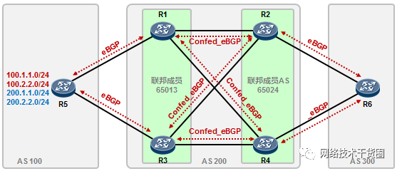
R1及R3处于联邦成员AS 65013;
R2、R4处于联邦成员AS 65024;
AS200内运行OSPF,所有路由器通告自己的Loopback0接口,联邦的邻居关系建立在Loopback0口上。
OSPF的配置在这里就不列举了。最终确保R6能够学习到100及200网段的路由。R1的配置如下:
[R1] bgp 65013
[R1-bgp] router-id 1.1.1.1
[R1-bgp] confederation id 200
[R1-bgp] confederation peer-as 65024
[R1-bgp] peer 10.1.15.5 as-number 100
[R1-bgp] peer 2.2.2.2 as-number 65024
[R1-bgp] peer 2.2.2.2 connect-interface loopback0
[R1-bgp] peer 2.2.2.2 next-hop-local
[R1-bgp] peer 2.2.2.2 ebgp-max-hop
[R1-bgp] peer 4.4.4.4 as-number 65024
[R1-bgp] peer 4.4.4.4 connect-interface loopback0
[R1-bgp] peer 4.4.4.4 ebgp-max-hop
[R1-bgp] peer 4.4.4.4 next-hop-local
R3的配置如下:
[R3] bgp 65013
[R3-bgp] router-id 3.3.3.3
[R3-bgp] confederation id 200
[R3-bgp] confederation peer-as 65024
[R3-bgp] peer 10.1.35.5 as-number 100
[R3-bgp] peer 2.2.2.2 as-number 65024
[R3-bgp] peer 2.2.2.2 connect-interface loopback0
[R3-bgp] peer 2.2.2.2 ebgp-max-hop
[R3-bgp] peer 2.2.2.2 next-hop-local
[R3-bgp] peer 4.4.4.4 as-number 65024
[R3-bgp] peer 4.4.4.4 connect-interface loopback0
[R3-bgp] peer 4.4.4.4 ebgp-max-hop
[R3-bgp] peer 4.4.4.4 next-hop-local
R2的配置如下:
[R2] bgp 65024
[R2-bgp] router-id 2.2.2.2
[R2-bgp] confederation id 200
[R2-bgp] confederation peer-as 65013
[R2-bgp] peer 1.1.1.1 as-number 65013
[R2-bgp] peer 1.1.1.1 connect-interface loopback0
[R2-bgp] peer 1.1.1.1 ebgp-max-hop
[R2-bgp] peer 3.3.3.3 as-number 65013
[R2-bgp] peer 3.3.3.3 connect-interface loopback0
[R2-bgp] peer 3.3.3.3 ebgp-max-hop
[R2-bgp] peer 10.1.26.6 as-number 300
R4的配置如下:
[R4] bgp 65024
[R4-bgp] router-id 4.4.4.4
[R4-bgp] confederation id 200
[R4-bgp] confederation peer-as 65013
[R4-bgp] peer 1.1.1.1 as-number 65013
[R4-bgp] peer 1.1.1.1 connect-interface loopback0
[R4-bgp] peer 1.1.1.1 ebgp-max-hop
[R4-bgp] peer 3.3.3.3 as-number 65013
[R4-bgp] peer 3.3.3.3 connect-interface loopback0
[R4-bgp] peer 3.3.3.3 ebgp-max-hop
[R4-bgp] peer 10.1.46.6 as-number 300
R5的配置如下:
[R5] bgp 100
[R5-bgp] router-id 5.5.5.5
[R5-bgp] peer 10.1.15.1 as-number 200
[R5-bgp] peer 10.1.35.3 as-number 200
[R5-bgp] network 100.1.1.0 255.255.255.0
[R5-bgp] network 100.2.2.0 255.255.255.0
[R5-bgp] network 200.1.1.0 255.255.255.0
[R5-bgp] network 200.2.2.0 255.255.255.0
R6的配置如下:
[R6] bgp 300
[R6-bgp] router-id 6.6.6.6
[R6-bgp] peer 10.1.26.2 as-number 200
[R6-bgp] peer 10.1.46.4 as-number 200
[R5]display bgp peer
BGP local router ID : 5.5.5.5
Local AS number : 100
Total number of peers : 2 Peers in established state : 2
Peer V AS MsgRcvd MsgSent OutQ Up/Down State Pref Rcv
10.1.15.1 4 200 3 7 0 0022 Established 0
10.1.35.3 4 200 3 7 0 0022 Established 0
[R1]display bgp peer
BGP local router ID : 1.1.1.1
Local AS number : 65013
Total number of peers : 3 Peers in established state : 3
Peer V AS MsgRcvd MsgSent OutQ Up/Down State PrefRcv
2.2.2.2 4 65024 6 8 0 0005 Established 0
4.4.4.4 4 65024 5 7 0 0038 Established 0
10.1.15.5 4 100 8 5 0 0039 Established 4
观察一下路由:
[R2]display bgp routing-table
BGP Local router ID is 2.2.2.2
Status codes: * - valid, > - best, d - damped,
h - history, i - internal, s - suppressed, S - Stale
Origin : i - IGP, e - EGP, ? - incomplete
Total Number of Routes: 8
Network NextHop MED LocPrf PrefVal Path/Ogn
*>i 100.1.1.0/24 1.1.1.1 0 100 0 (65013) 100 i
* i 3.3.3.3 0 100 0 (65013) 100 i
*>i 100.2.2.0/24 1.1.1.1 0 100 0 (65013) 100 i
* i 3.3.3.3 0 100 0 (65013) 100 i
*>i 200.1.1.0 1.1.1.1 0 100 0 (65013) 100 i
* i 3.3.3.3 0 100 0 (65013) 100 i
*>i 200.2.2.0 1.1.1.1 0 100 0 (65013) 100 i
* i 3.3.3.3 0 100 0 (65013) 100 i
上面是R2的BGP表,关注一下AS_PATH属性值,()括号内的AS号为联邦成员AS号。
[R6]display bgp routing-table
BGP Local router ID is 6.6.6.6
Status codes: * - valid, > - best, d - damped,
h - history, i - internal, s - suppressed, S - Stale
Origin : i - IGP, e - EGP, ? - incomplete
Total Number of Routes: 8
Network NextHop MED LocPrf PrefVal Path/Ogn
*> 100.1.1.0/24 10.1.26.2 0 200 100i
* 10.1.46.4 0 200 100i
*> 100.2.2.0/24 10.1.26.2 0 200 100i
* 10.1.46.4 0 200 100i
*> 200.1.1.0 10.1.26.2 0 200 100i
* 10.1.46.4 0 200 100i
*> 200.2.2.0 10.1.26.2 0 200 100i
* 10.1.46.4 0 200 100i
R6已经能够学习到100及200网段的路由了,并且这些路由的AS_PATH中是看不到联邦的信息。
审核编辑:郭婷
-
动态BGP与静态BGP的区别?2025-06-24 4752
-
华为路由器BGP基础配置实验记录2024-01-06 3407
-
BGP硬核笔记分享2023-12-11 2125
-
动态BGP与静态BGP的区别2023-12-01 7850
-
如何配置Cilium和BGP协同工作呢?2023-08-15 5554
-
BGP知识点总结2023-04-10 2518
-
跟大家聊聊BGP与OSPF2023-01-30 5118
-
BGP路由优选规则的深入了解2022-11-14 5928
-
动态BGP是什么,如何判定它的真假2022-04-18 1807
-
什么是BGP高防,BGP高防的优势是什么2019-12-28 1524
-
bgp路由协议的路由属性_BGP路由协议的优势2019-08-20 4327
-
测量BGP传递时间2019-07-22 833
-
Zebra与BGP路由监测的实现2010-12-25 985
全部0条评论

快来发表一下你的评论吧 !
