
资料下载


Nero:控制远程设备的智能手套
胡秋阳
分享资料个
描述
探索医疗保健和医药行业等众多行业的所有可能奇迹已成为一项关键而艰巨的任务,在这些行业中,手术涉及精确度和来自世界各地专家的意见,在化学制造厂、包装和生产行业等地方,以及所有具有恶劣化学环境的商业领域。该项目只是所有所述问题的解决方案。Nero 是一个飞跃,使所有仅靠人工干预和技能无法完成的任务成为可能。
这种手势控制的智能机器人手套使我们能够使用现有技术实现经济的解决方案。它可以用于控制和自动化机器,如机械臂、传送带、滑轮、起重机和无数其他设备。
您的想象力是 Nero 效率的极限。该项目为我们提供了非凡的精度、准确性,并为进一步的可访问性和自动化提供了自由。
尼禄在行动!
概述
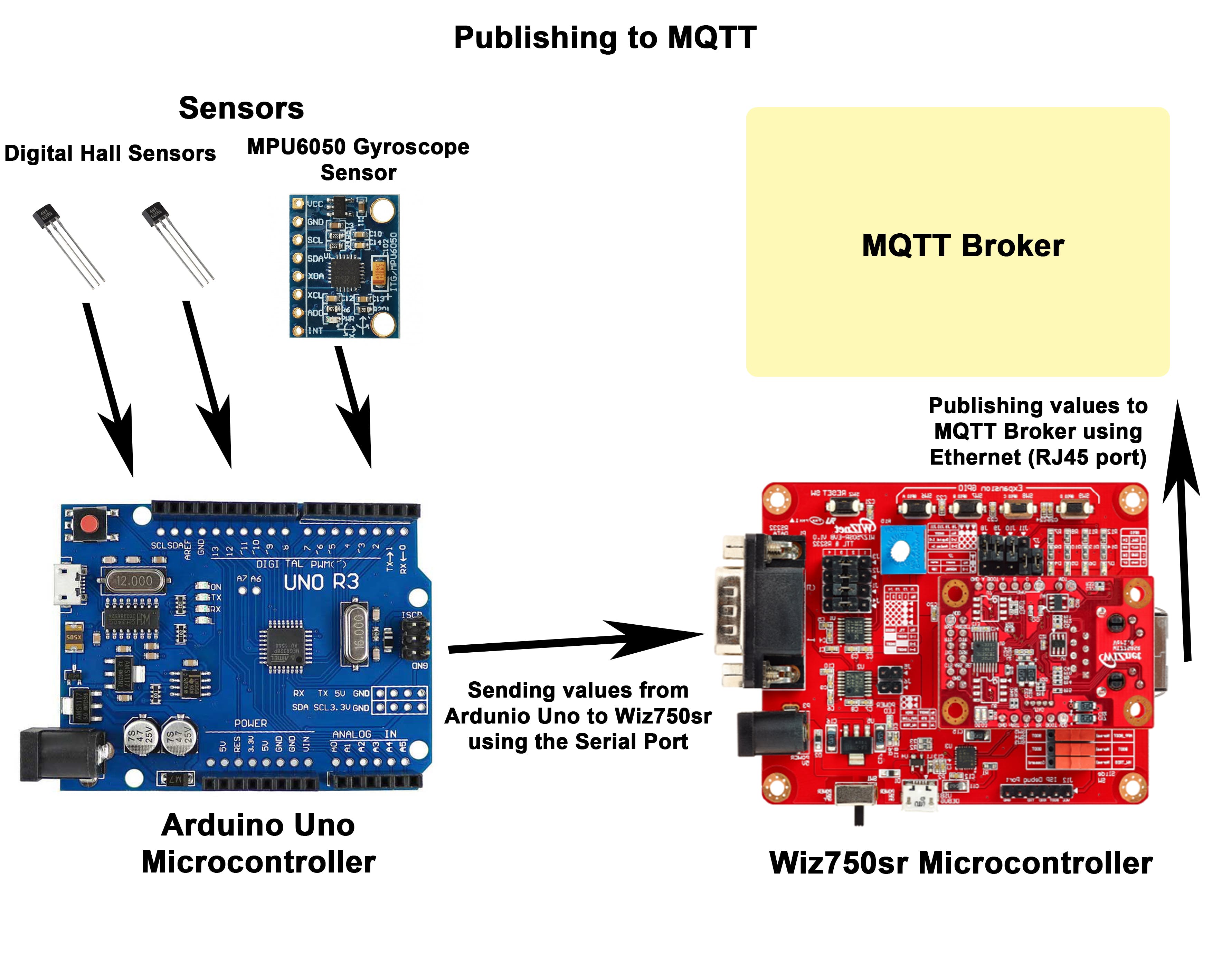
在这个项目中,我们基本上有 2 个主要部分,传输端和接收端。我们利用 WIZnet 串口转以太网板将从 arduino 接收到的数据发布到 MQTT 代理,并使用 nodeMCU 在接收端订阅数据。两端的技术步骤将在下一节中详细介绍。
脚步
发射端
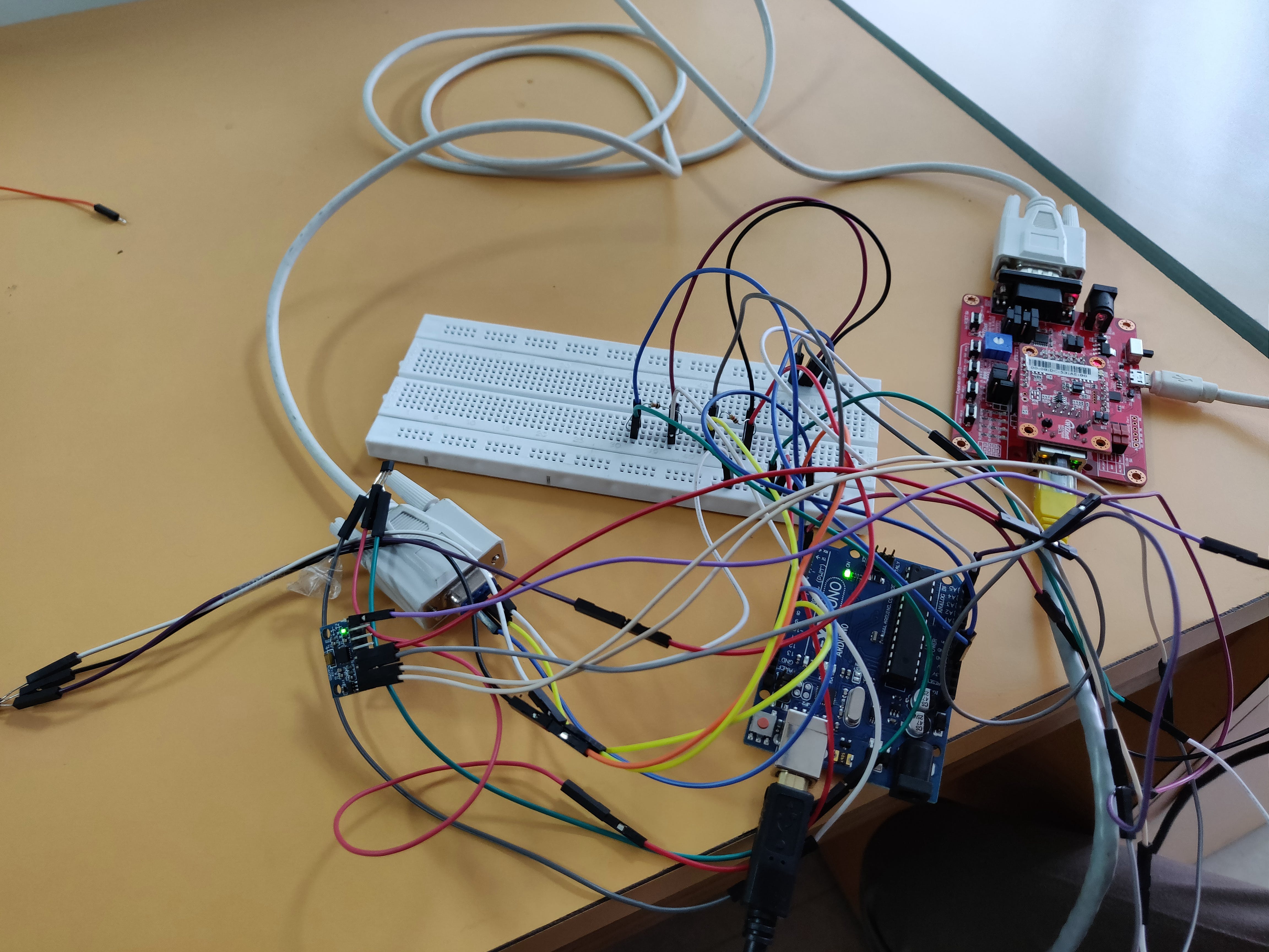
电路连接:
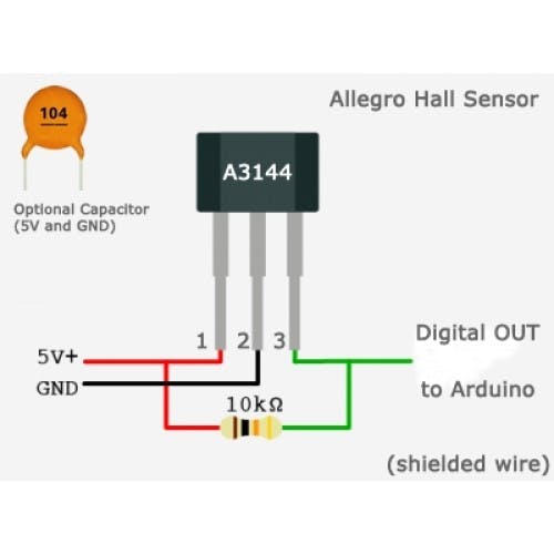
第 1 步:将霍尔效应传感器 (A3144) 和陀螺仪传感器 (MPU6050) 连接到 arduino,如下所示。(请参阅连接的引脚图)
o 霍尔传感器连接到 arduino 的 d9 和 d6
第 2 步:使用 RS-232 电缆将 Arduino Uno 连接到 WIZ750SR 板(带有串口到以太网转换器),如下所示:
o Arduino Uno 的发送引脚(本例中为引脚 11)使用 RS-232 电缆和跳线连接到 WIZ750SR 串口转以太网的接收引脚。
o Arduino 的接收引脚(本例中为引脚 10)连接到发送引脚。
o Arduino 的接地引脚连接到 WIZnet 板的接地引脚。
第 3 步:使用以太网 LAN 电缆将 WIZnet 板连接到网络(用于 MQTT 连接)。
第 4 步:将两块板连接到 PC 以上传代码。
-发送方代码:
将代码上传到串口转以太网板的步骤:
1. 将开机开关从正常模式推到开机模式。
2、使用ISP工具软件打开串口。
3. 显示“serial open complete”后,上传“os.mbed”编译代码。
4.将开机开关推回正常位置,重新设置wiz板。
5.板子接收到的数据可以使用“COOLTERM”进行监控。
//Code to publish data from the Wiznet Board
#include "mbed.h"
#include "MQTTEthernet.h"
#include "MQTTClient.h"
#define ECHO_SERVER_PORT   7
Serial a(D1,D0);
   Serial s(USBTX, USBRX);
int arrivedcount = 0;
void messageArrived(MQTT::MessageData& md)
{
   MQTT::Message &message = md.message;
   printf("Message arrived: qos %d, retained %d, dup %d, packetid %d\n", message.qos, message.retained, message.dup, message.id);
   printf("Payload %.*s\n", message.payloadlen, (char*)message.payload);
   ++arrivedcount;
}
void baud(int baudrate) {
   s.baud(baudrate);
}
int main (void)
{
   baud(9600);
   printf("Wait a second...\r\n");
   char* topic = "Ultrasonic";
   MQTTEthernet ipstack = MQTTEthernet();
   MQTT::Client client = MQTT::Client(ipstack);
,>,>   char* hostname = "172.16.73.4";
   int port = 1883;
   int rc = ipstack.connect(hostname, port);
   if (rc != 0)
       printf("rc from TCP connect is %d\n", rc);
   printf("Topic: %s\r\n",topic);
   MQTTPacket_connectData data = MQTTPacket_connectData_initializer;
   data.MQTTVersion = 3;
   data.clientID.cstring = "parents";
   if ((rc = client.connect(data)) != 0)
       printf("rc from MQTT connect is %d\n", rc);
   if ((rc = client.subscribe(topic, MQTT::QOS0, messageArrived)) != 0)
       printf("rc from MQTT subscribe is %d\n", rc);
   MQTT::Message message;
   char buf[100];
   while (true)
   {
       char b;
       int i=0;
       char q[100];
       if(a.readable())
       {
           for(i=0;i<=1;i++)
           {
           b= a.getc();
           q[i]=b;
           s.printf("%c",q[i]);
           }
       sprintf(buf,"%s",q);
       message.qos = MQTT::QOS1;
       message.retained = false;
       message.dup = false;
       message.payload = (void*)buf;
       message.payloadlen = strlen(buf);
       rc = client.publish("Ultrasonic", message);
       client.yield(2000);
           }
           }
}
将代码上传到 Arduino Uno 的步骤:
- 将 Arduino Uno 连接到 PC。
- 从工具->端口选择正确的 COM 端口。
- 从 Tools->Boards 选择 Arduino Uno。
- 编译并上传代码。
//Arduino code to recieve values of the sensors and serially transmit it to the wiznet  board
//defines pins numbers
#include#include"Wire.h"
//I2Cdev and MPU6050 must be installed as libraries, or else the .cpp/.h files
//for both classes must be in the include path of your project
#include"I2Cdev.h"
#include"MPU6050.h"
//class default I2C address is 0x68
//specific I2C addresses may be passed as a parameter here
//AD0 low = 0x68 (default for InvenSense evaluation board)
//AD0 high = 0x69
MPU6050accelgyro;
int16_tax, ay, az;
int16_tgx, gy, gz;
SoftwareSerialmySerial(10, 11); // RX, TX
inthPin=9;
intvalue1;
intmyInts[2];
constint trigPin = 3;
constint echoPin = 2;
longduration;
intdistance;
inthPin1=6;
inthState1=0;
intvalue;
inthState=0;
intolds=0;
intod;
intolds1=0;
//accelerometer values
intaccel_reading;
intaccel_corrected;
intaccel_offset = 200;
floataccel_angle;
floataccel_scale = 1; // set to 0.01
voidsetup() {
//join I2C bus (I2Cdev library doesn't do this  automatically)
Wire.begin();
 accelgyro.initialize();
 pinMode(trigPin,OUTPUT); // Sets the trigPin as an Output
pinMode(echoPin,INPUT); // Sets the echoPin as an Input
 //put your setup code here, to run once:
Serial.begin(9600);
 //put your setup code here, to run once:
pinMode(hPin,INPUT);
pinMode(hPin1,INPUT);
 mySerial.begin(9600);
 pinMode(LED_BUILTIN,OUTPUT);
olds=olds1=80;
}
voidloop() {
digitalWrite(trigPin,LOW);
delayMicroseconds(2);
// Sets the trigPin onHIGH state for 10 micro seconds
digitalWrite(trigPin,HIGH);
delayMicroseconds(10);
digitalWrite(trigPin,LOW);
// Reads the echoPin,returns the sound wave travel time in microseconds
duration =pulseIn(echoPin, HIGH);
// Calculating thedistance
distance=duration*0.034/2;
// Prints the distanceon the Serial Monitor
accelgyro.getMotion6(&ax,&ay, &az, &gx, &gy, &gz);
 //accelerometer_X_Axis angle calc
 accel_reading= ax;
 accel_corrected= accel_reading - accel_offset;
 accel_corrected= map(accel_corrected, -16800, 16800, -90, 90);
 accel_corrected= constrain(accel_corrected, -90, 90);
 accel_angle= (float)(accel_corrected * accel_scale);
  // put your main code here, to run repeatedly:
 hState=digitalRead(hPin);
 hState1=digitalRead(hPin1);
if(hState != olds ||hState1 != olds1){
 if(hState==LOW && hState1==LOW){
value=1;
olds = hState;
olds1 = hState1;
}
if (hState1==HIGH&& hState==LOW){
value=2;
olds = hState;
olds1 = hState1; }
if (hState1==LOW&& hState==HIGH){
value=3;
olds = hState;
olds1 = hState1;}
if (hState1==HIGH&& hState==HIGH){
value=4;
olds = hState;
olds1 = hState1;
}
}
else{
  if(accel_angle>=0 &&accel_angle<=30)
  {
 value= 5;
 od=value;
  }
 elseif(accel_angle>=30 && accel_angle<70)
 {
 value=6;
 od=value;
 }
 elseif(accel_angle>=70 && accel_angle<=90)
 {
 value=7;
 od=value;
 }
 else{
 if(od==0){
 value=5;
 }
 else{
 value=od;}
 }
}
mySerial.println(value);
Serial.println(value);
delay(1000);
}
接收方
- 电路连接
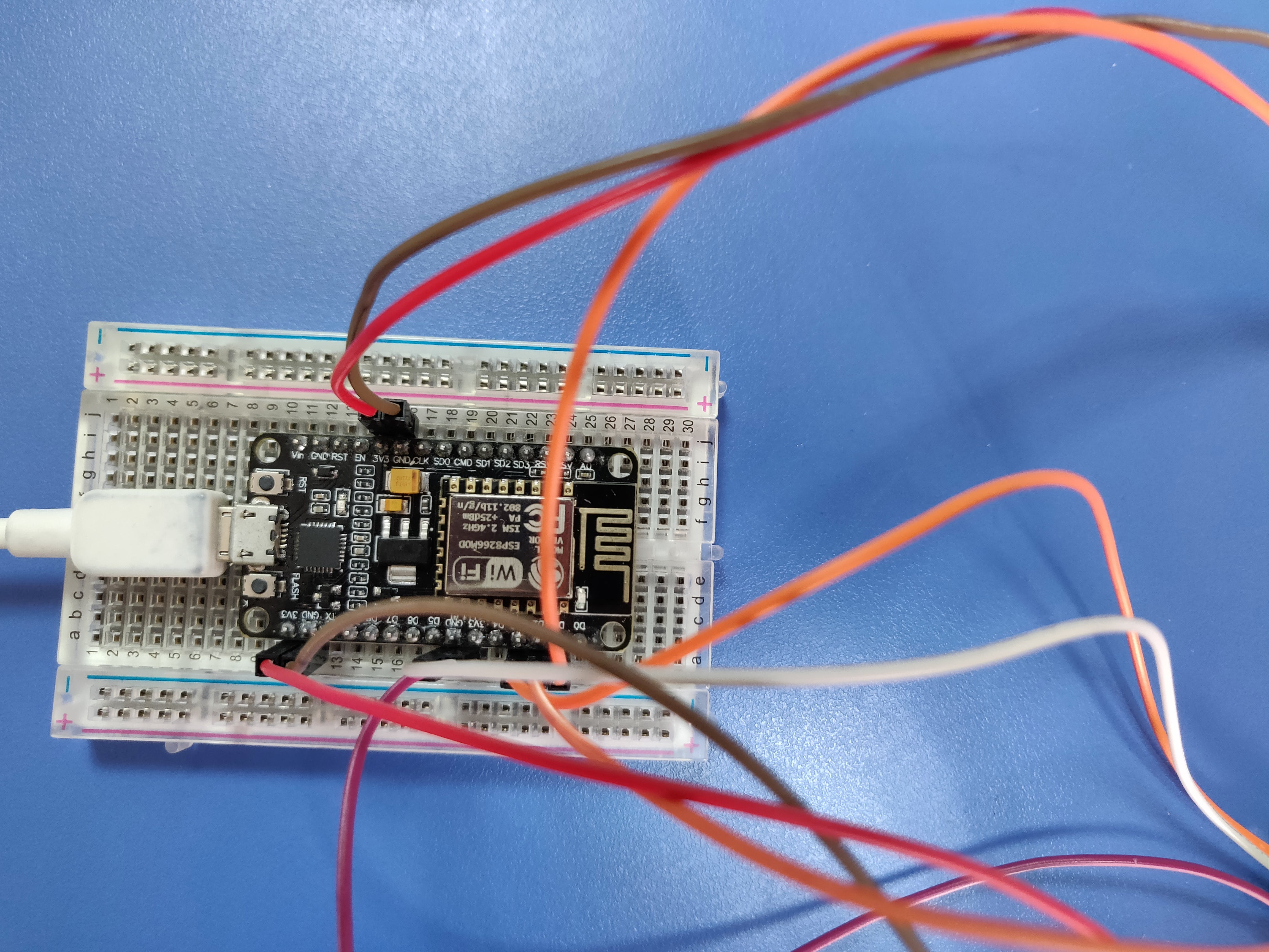
第 1 步:将三个伺服电机连接到 NodeMCU。
第二步:按照下图定位伺服电机。
第三步:通过PC将代码上传到NodeMCU(ESP8266)。
第 4 步:检查串行监视器上的输出。
- 接收方代码:
将代码上传到 NodeMCU 的步骤:
- 将 NodeMCU (ESP8266) 连接到 PC。
- 从工具->端口选择正确的 COM 端口。
- 将所需的库添加到 Ardunio 编译器。(参考 1.1)
- 从 Tools->Boards 选择 NodeMCU (ESP8266)。
- 编译并上传代码。
/*
This code basically sets up an ESP8266 board as a MQTT client and helps in subscribing to desired topics that are published.
It is required that the board in the 'Tools' section must be selected to NodeMCU and the ESP8266 drivers are installed.
The baud rate must be set at 115200
Here we are operating three servo motors using the nodeMCU based on the values received via the MQTT topic
*/
#include
#include
#include
// Creating objects for the 3 servo motors
Servo servo;
Servo servo1;
Servo servo2;
// The pins we have used for the servo motors are D1,D2 and D3
// Update these with values suitable for your network.
const char* ssid = "CDI";
const char* password = "Cdi*1717";
const char* mqtt_server = "172.16.73.4";
WiFiClient espClient;
PubSubClient client(espClient);
long lastMsg = 0;
char msg[50];
int value = 0;
char old ;
void setup() {
 //Initial Setup Code
 Serial.begin(115200);
 setup_wifi();
 client.setServer(mqtt_server, 1883);
 client.setCallback(callback);
 delay(1000);
}
//Code for connecting to the wifi
void setup_wifi() {
 delay(10);
 // We start by connecting to a WiFi network
 Serial.println();
 Serial.print("Connecting to ");
 Serial.println(ssid);
 WiFi.begin(ssid, password);
 while (WiFi.status() != WL_CONNECTED) {
   delay(500);
   Serial.print(".");
 }
 Serial.println("");
 Serial.println("WiFi connected");
 Serial.println("IP address: ");
 Serial.println(WiFi.localIP());
}
//This function is responsible for subscribing to a topic and receiving the values from it
void callback(char* topic, byte* payload, unsigned int length) {
 Serial.print("Message arrived [");
 Serial.print(topic);
 Serial.print("] ");
 old = (char)payload[0];
 //detach each time to avoid jitter of the servo motors
 servo2.detach();
 servo.detach();
 servo1.detach();
for (int i = 0; i < length; i++) {
 Serial.println("Received message is :");
 Serial.println((char)payload[i]);
 servo.detach();
 servo1.detach();
 servo2.detach();
 if((char)payload[i] == '1')
 {
   servo.detach();
   servo2.detach();
   servo1.detach();
   servo.attach(0);
   servo.write(89);
   delay(1000);
   servo.detach();
   servo1.attach(4);
   servo1.write(89);
   delay(1000);
   servo1.detach();
   servo2.detach();
   old='1';
   break;
 }
if((char)payload[i] == '2')
 {
   servo.detach();
   servo2.detach();
   servo1.detach();
   servo1.attach(4);
   servo1.write(89);
   delay(1000);
   servo1.detach();
   servo2.detach();
   old='2';
   break;
 }
if((char)payload[i] == '3')
 {
   servo.detach();
   servo2.detach();
   servo1.detach();
   servo.attach(0);
   servo.write(89);
   delay(1000);
   servo.detach();
   servo2.detach();
   old='3';
   break;
 }
if((char)payload[i] == '4')
 {
   servo.detach();
   servo1.detach();
   servo2.detach();
   servo.attach(0);
   servo.write(180);
   delay(1000);
   servo.detach();
   servo1.attach(4);
   servo1.write(180);
   delay(1000);
   servo1.detach();
   servo2.detach();
   old='4';
   break;
 }
 if((char)payload[i]=='5')
 {
   servo2.detach();
   servo2.attach(5);
   servo2.write(179);
   delay(1000);
   servo2.detach();
 }
 if((char)payload[i]=='6')
 { servo2.detach();
   servo2.attach(5);
   servo2.write(89);
   delay(1000);
   servo2.detach();
  }
 if((char)payload[i]=='7')
 { servo2.detach();
   servo2.attach(5);
   servo2.write(2);
   delay(1000);
   servo2.detach();
 }
   servo2.detach();
 }
   servo.detach();
   servo1.detach();
   servo2.detach();
}
//This function is to reconnect once the connection is lost
void reconnect() {
 // Loop until we're reconnected
 while (!client.connected()) {
   Serial.print("Attempting MQTT connection...");
   // Attempt to connect
   if (client.connect("ESP8266Client")) {
     Serial.println("connected");
     // Once connected, publish an announcement...
     // ... and resubscribe
     client.subscribe("Ultrasonic");
   } else {
     Serial.print("failed, rc=");
     Serial.print(client.state());
     Serial.println(" try again in 5 seconds");
     // Wait 5 seconds before retrying
     delay(5000);
   }
 }
}
void loop() {
 if (!client.connected()) {
   reconnect();
 }
 client.loop();
}
未来的改进
我们的目标是减少延迟时间并开发客户端监控应用程序作为进一步改进,使该项目可在各种行业中实施。
声明:本文内容及配图由入驻作者撰写或者入驻合作网站授权转载。文章观点仅代表作者本人,不代表电子发烧友网立场。文章及其配图仅供工程师学习之用,如有内容侵权或者其他违规问题,请联系本站处理。 举报投诉
- 相关下载
- 相关文章


