

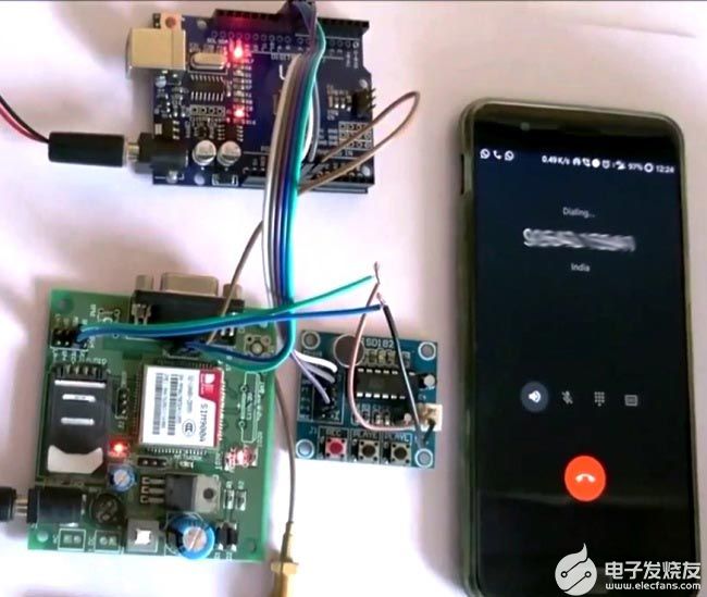
如何使用Arduino和GSM模块制作一个自动呼叫应答机
描述
在当今的现代世界中,我们都依赖手机作为无线通信的主要手段。但是,我们都遇到过可能无法接听电话的情况,这些电话可能是重要的个人电话或改变生活的商务电话,您可能错过了那个机会,因为您无法在那个特定时间接听该电话。
该项目旨在通过使用Arduino和GSM模块创建自动呼叫应答机来解决此问题。下次当您更换新电话号码或外出进行长途朝圣旅行或享受当之无愧的假期时,只需使用此机器录制您的声音,说明缺席的原因,您的所有电话将自动由这台机器接听,您录制的声音将播放给他们。这也可用于您的业务号码,以便在非办公时间接听客户的呼叫。听起来很有趣吧?所以让我们构建它..
所需材料:
该项目可能听起来有点复杂,但它真的很容易构建,你只需要以下组件
Arduino Uno
GSM 模块 – 飞鳞 SIM 900
ISD 1820 语音模块
12V 适配器为 GSM 模块供电
9V 电池为 Arduino 供电
连接线
在我们实际进入项目之前,让我们熟悉GSM模块和ISD 1820语音模块
飞秤 SIM900 GSM 模块:
GSM模块使用起来非常吸引人,尤其是当我们的项目需要远程访问时。这些模块可以执行我们普通手机可以执行的所有操作,例如拨打/接听电话,发送/接收短信,使用GPRS连接到互联网等。您还可以将普通麦克风和扬声器连接到此模块,并在移动通话中交谈。
如下图所示,GSM模块带有一个USART适配器,可以使用MAX232模块直接连接到计算机,或者可以使用Tx和Rx引脚将其连接到微控制器。您还可以注意到可以连接麦克风或扬声器的其他引脚,如MIC +,MIC-,SP+,SP-等。该模块可以通过普通的直流桶形插孔由12V 适配器供电。
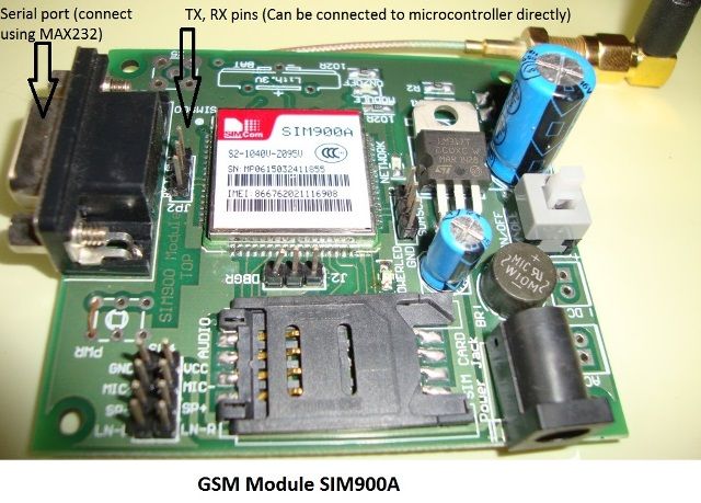
将SIM卡插入模块插槽并打开电源,您应该注意到电源指示灯亮起。现在等待一分钟左右,您应该会看到红色(或任何其他颜色)LED 每 3 秒闪烁一次。这意味着您的模块能够与您的SIM卡建立连接。现在,您可以继续将模块与手机或任何微控制器连接。
ISD1820 语音模块:
ISD 1820语音模块确实是一个很酷的模块,可以通过语音公告为您的项目增添趣味。该模块能够录制音频剪辑 10 秒,然后在需要时播放。模块本身带有麦克风和扬声器(8欧姆0.5瓦),它应该看起来像下面显示的那样。
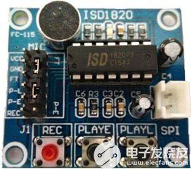
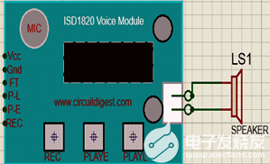
该模块工作在+5V电压下,可以使用左侧的操纵杆供电。它在底部还有三个按钮,分别是Rec.按钮,PlayE。按钮和播放L。按钮。您可以通过按录制按钮录制您的声音,并使用 PlayE 按钮播放。只要您按住按钮,PlayL 就会播放语音。与MCU接口时,我们可以使用左侧的引脚。这些引脚可承受 3V-5V,因此可由 Arduino/ESP8266 直接驱动。在我们的项目中,我们使用Arduino模块的D8引脚控制PLAYE引脚。这样我们就可以在GSM模块检测到并接听呼叫时播放录制的语音。
电路图及说明:
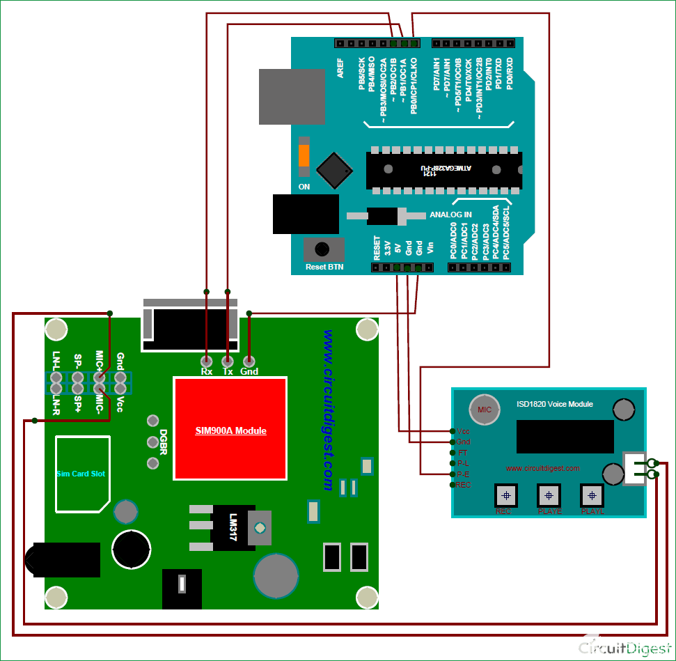
上面给出了该自动语音呼叫应答机项目的完整电路图。如您所见,连接非常简单。我们使用 12V 1A 适配器为 GSM 模块供电,使用 9V 电池为 Arduino 供电,ISD 语音模块由 Arduino 的 +5V 引脚供电。众所周知,我们可以通过按下rec按钮在语音模块上录制任何内容,这将在按下P-E时播放,此音频必须发送到GSM模块的麦克风。因此,我们将语音模块的扬声器引脚连接到GSM模块的麦克风引脚。
这里,Arduino和GSM模块串行连接,Arduino的Tx引脚连接到引脚9,Rx引脚连接引脚10。这将有助于Arduino收听GSM模块。当呼叫到达GSM模块时,Arduino将收听它并要求GSM模块应答呼叫。Arduino 确保呼叫处于活动状态,然后通过使引脚 8(连接到语音模块的 P-E)高电平 200 毫秒,在语音模块上播放录制的语音消息。
对 Arduino 进行编程:
从上面的段落中我们知道Arduino在这里的作用是什么;现在让我们看一下执行相同操作的代码。该项目的完整Arduino代码在本页底部给出,在这里我将代码分成小垃圾来解释它。
在我们进一步安装 GSM 库之前,请单击此 Github GSM 库链接以下载此项目中使用的库。您将获得一个zip文件,该文件必须通过Sketch -> Include Librarey -> Add添加到Arduino库中。压缩文件。
下面显示的代码的前三行用于将库包含在我们的代码中。我们使用串行库和线库,因为我们没有使用 Arduino 的默认 Rx 和 Tx 引脚与 GSM 模块通信。
#include //download librarey from https://github.com/Seeed-Studio/GPRS_SIM900
#include //default librarey
#include //default library
我们使用以下线路在引脚 9 和 10 上启用串行通信。这是我们上面包含的软件串行库实现的。
SoftwareSerial gprs(9,10);//TX,RX
在我们的设置函数中,我们以 9600 波特率初始化串行监视器,GSM 模块也使用 9600 波特率初始化。触发语音的引脚 8 被声明为输出引脚。
void setup(){
Serial.begin(9600); //Serial monitor works on 9600 baudrate for debugging
sim900_init(&gprs, 9600); //GSM module works on 9600 baudrate
pinMode(8, OUTPUT); //pin to turn on Voice
Serial.println("Arduino - Automatic Voice Machine");
}
接下来,我们必须创建一个函数,该函数可以通过其串行端口读取和理解GSM模块所说的内容。如果我们使用简单的串行读取行(如“gprs.read()”来读取消息,我们将以 ASCII 十进制值的形式获取它们,这对我们来说毫无意义。
因此,以下函数用于使用字符串对象将这些十进制值转换为字符串,然后将它们连接起来形成字符串。最终的字符串值存储在变量 Fdata 中,该变量为字符串类型,可用于与任何字符串值进行比较。
void check_Incoming()
{
if(gprs.available()) //If GSM is saying something
{
Incomingch = gprs.read(); // Listen to it and store in this variable
if (Incomingch == 10 || Incomingch ==13) //If it says space (10) or Newline (13) it means it has completed one word
{Serial.println(data); Fdata =data; data = ""; } //Print the word and clear the variable to start fresh
else
{
String newchar = String (char(Incomingch)); //convert the char to string by using string objects
data = data +newchar; // After converting to string, do string concatenation
}
}
}
以下行用于调试,使用这些调试器行,您可以将任何AT命令从Arduino的串行监视器发送到GSM,还可以查看串行监视器上的响应。
if(Serial.available()){ //Used for debugging
gprs.write(Serial.read()); //Used for debugging
} //Used for debugging
如前所述,Arduino必须检查GSM模块是否正在接收任何呼叫。这可以通过使Arduino检查“RING”来完成,因为GSM模块将根据AT命令列表在呼叫时输出RING。当它找到呼叫时,它将等待 5 秒钟并将命令“ATA”发送到 GSM 模块,这将使 GSM 模块接听呼叫,接听后它将响应“确定”。Arduino再次等待“OK”确认,然后将引脚8调高200ms,以播放来自语音模块的录制语音。
if (Fdata == "RING") //If the GSM module says RING
{
delay(5000); //wait for 5sec to create 3 ring delay.
gprs.write ("ATArn"); //Answer the call
Serial.println ("Placed Received"); //Used for debugging
while(Fdata != "OK") //Until call successfully answered
{check_Incoming(); //Read what GSM modue is saying
Serial.println ("Playing Recorded message"); //Used for debugging
//Play the recored voice message
delay(500);
digitalWrite(8, HIGH); //Go high
delay(200); // wait for 200 msec
digitalWrite(8, LOW); //Go low
}
加工:
一旦您的代码和硬件准备就绪,就该找点乐子了。打开两个模块的电源,然后按语音模块上的REC按钮并录制消息。此消息的长度只能为 10 秒。
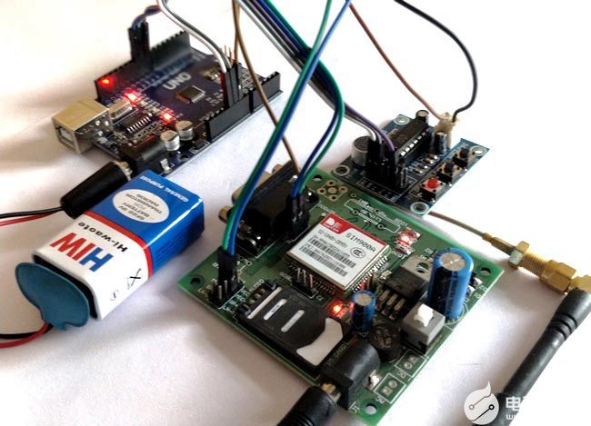
现在使用以下给定的代码对Arduino进行编程,并将SIM卡插入GSM模块,您应该等待至少2分钟,以便GSM模块可以与您的网络服务提供商建立连接。完成后,您应该会看到一个红色 LED 每 3 秒闪烁一次,这表明您的 SIM 卡已准备好接听电话。您现在可以尝试从任何号码拨打此SIM卡,并且您应该会在连续响铃三次后听到录制的消息。
/*
Automatic Voice machine using Arudino and GSM900
Created by: Aswinth Raj B
Coded on: 22-9-2017
Website: www.circuitdigest.com
*/
#include //download library from https://github.com/Seeed-Studio/GPRS_SIM900
#include //default library
#include //default library
int Incomingch;
String data,Fdata;
//Connect Tx pin of GSM to 9 of Arduino
//Connect Rx pin of GSM to 10 of Arduino
SoftwareSerial gprs(9,10);//TX,RX
void setup(){
Serial.begin(9600); //Serial monitor works on 9600 baudrate for debugging
sim900_init(&gprs, 9600); //GSM module works on 9600 baudrate
pinMode(8, OUTPUT); //pin to turn on Voice
Serial.println("Arduino - Automatic Voice Machine");
}
/*Function to read Incoming data from GSM to Arduino*/
void check_Incoming()
{
if(gprs.available()) //If GSM is saying something
{
Incomingch = gprs.read(); // Listen to it and store in this variable
if (Incomingch == 10 || Incomingch ==13) //If it says space (10) or Newline (13) it means it has completed one word
{Serial.println(data); Fdata =data; data = ""; } //Print the word and clear the variable to start fresh
else
{
String newchar = String (char(Incomingch)); //convert the char to string by using string objects
data = data +newchar; // After converting to string, do string concatenation
}
}
}
/*##End of Function##*/
void loop(){
check_Incoming(); //Read what GSM module is saying
if(Serial.available()){ //Used for debugging
gprs.write(Serial.read()); //Used for debugging
} //Used for debugging
if (Fdata == "RING") //If the GSM module says RING
{
delay(5000); //wait for 5sec to create 3 ring delay.
gprs.write ("ATArn"); //Answer the call
Serial.println ("Placed Received"); //Used for debugging
while(Fdata != "OK") //Until call successfully answered
{check_Incoming(); //Read what GSM module is saying
Serial.println ("Playing Recorded message"); //Used for debugging
//Play the recorded voice message
delay(500);
digitalWrite(8, HIGH); //Go high
delay(200); // wait for 200 msec
digitalWrite(8, LOW); //Go low
}
}
}
-
某型空管二次雷达应答机系统设计2019-06-18 2909
-
航管应答机的接口类型有哪些?2019-08-12 2644
-
询问-应答机制的描述2009-03-01 1541
-
基于OP7200的应答机自动测试系统2011-05-12 1043
-
Cobham AvComm推出用于测试应答机和测距的新型综合测试仪2015-05-04 2188
-
基于单片机的航管应答机高度模拟器解析2017-11-16 1194
-
应答机器人可通过导航系统传达实时灾情2017-12-30 1048
-
用Arduino和其他模块制作一个悬停板2019-05-22 2421
-
使用GSM和Arduino的基本电话的制作2019-10-17 5021
-
Airboxer无人直升机上已成功集成了MXS应答机2020-04-12 1591
-
某星载应答机电磁兼容性设计案例讲解2020-12-24 1659
-
使用GSM模块制作家庭自动化设备2022-11-16 672
-
如何制作基于Arduino的自动开门2023-06-29 1389
-
用Arduino做一个自动割草机2023-07-07 3772
-
带有集成DST80认证、EEPROM和LF发动机防盗系统的数字签名应答机数据表2024-03-21 449
全部0条评论

快来发表一下你的评论吧 !
