

LPC5516_SDK例程ADC_2Msps高速采集
描述
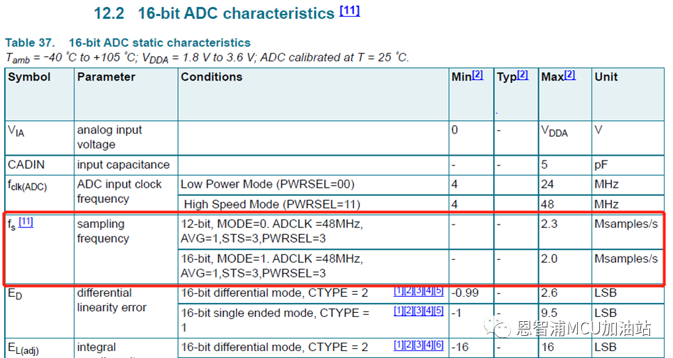
最近支持一个客户,需要在LPC5516下实现ADC 2Msps高速采集,根据数据手册描述:
-
ADC在12-bit模式下最高可以达到2.3Msps
-
ADC在16-bit模式下最高可以达到2.0Msps.
那么实际情况是否真如数据手册所述,能达到如此高的转换速率呢?小编这次就编写了测试代码进行了实测,结果为:
12-bit模式下ADC最快可达2.326Msps, 16-bit模式下2.083Msps, 结果还是和数据手册很吻合的。
代码设计
代码基于SDK的例程:
SDK_2_12_0_LPCXpresso55S16oardslpcxpresso55s16driver_exampleslpadcdma
修改:
1. 为了实现最快速度ADC采集,我们需要将ADC配置为:
-
ADC输入时钟: ADCCLK = 48MHz
-
无硬件平均: HWAVG=1
-
ADC采样时长设置为最短3xCLK: STS=0
-
ADC功率最大: PWRSEL=3
除此之外,还需要将ADC设置为连续转换模式:即将g_LpadcCommandConfigStruct.chainedNextCommandNumber指向自己,即完成当前转换后,自动开始下次转换。
以上所有配置对应SDK代码如下:
/* Configure ADC. */
LPADC_GetDefaultConfig(&lpadcConfigStruct);
lpadcConfigStruct.enableAnalogPreliminary = true;
lpadcConfigStruct.conversionAverageMode = kLPADC_ConversionAverage1;
lpadcConfigStruct.powerLevelMode=kLPADC_PowerLevelAlt4;
lpadcConfigStruct.referenceVoltageSource = DEMO_LPADC_VREF_SOURCE;
lpadcConfigStruct.FIFO0Watermark = 2;
LPADC_GetDefaultConvCommandConfig(&g_LpadcCommandConfigStruct);
g_LpadcCommandConfigStruct.channelNumber = DEMO_LPADC_USER_CHANNEL;
g_LpadcCommandConfigStruct.sampleTimeMode = kLPADC_SampleTimeADCK3;
g_LpadcCommandConfigStruct.loopCount = 1;
g_LpadcCommandConfigStruct.conversionResolutionMode = kLPADC_ConversionResolutionHigh;
// g_LpadcCommandConfigStruct.conversionResolutionMode =kLPADC_ConversionResolutionStandard;
g_LpadcCommandConfigStruct.chainedNextCommandNumber = DEMO_LPADC_USER_CMDID;
2. 配置DMA,使用DMA Ping-Pang buffer接收ADC数据,即定义两个DMA描述符,A和B:A传输完成后自动触发B,B传输完成后自动触发A。对应SDK代码为:
1. SDK_ALIGN(uint32_t s_dma_table[DMA_DESCRIPTOR_NUM * sizeof(dma_descriptor_t)], FSL_FEATURE_DMA_LINK_DESCRIPTOR_ALIGN_SIZE);
2.
3. const uint32_t g_XferConfig =
4. DMA_CHANNEL_XFER(true, /* Reload linkdescriptor after current exhaust, */
5. true, /* Clear trigger status.*/
6. true, /* Enable interruptA. */
7. false, /* Not enable interruptB. */
8. sizeof(uint32_t), /* Dma transfer width. */
9. kDMA_AddressInterleave0xWidth, /* Dma source address no interleave */
10. kDMA_AddressInterleave1xWidth, /* Dma destination address nointerleave */
11. sizeof(uint32_t)*ADC_DMA_SIZE /* Dma transfer byte. */
12. );
static void DMA_Configuration(void)
{
dma_channel_config_t dmaChannelConfigStruct;
#if defined (DEMO_DMA_HARDWARE_TRIGGER) && DEMO_DMA_HARDWARE_TRIGGER
/* Configure INPUTMUX. */
INPUTMUX_Init(DEMO_INPUTMUX_BASE);
INPUTMUX_AttachSignal(DEMO_INPUTMUX_BASE, DEMO_DMA_ADC_CHANNEL, DEMO_DMA_ADC_CONNECTION);
#endif /* DEMO_DMA_HARDWARE_TRIGGER */
/* Configure DMA. */
DMA_Init(DEMO_DMA_BASE);
DMA_EnableChannel(DEMO_DMA_BASE, DEMO_DMA_ADC_CHANNEL);
DMA_CreateHandle(&g_DmaHandleStruct, DEMO_DMA_BASE, DEMO_DMA_ADC_CHANNEL);
DMA_SetCallback(&g_DmaHandleStruct, DEMO_DMA_Callback, NULL);
/* Prepare and submitthe transfer. */
DMA_PrepareChannelTransfer(&dmaChannelConfigStruct, /* DMA channel transfer configuration structure. */
(void *)DEMO_LPADC_RESFIFO_REG_ADDR, /* DMA transfer source address.*/
(void *)adc_result, /* DMA transfer destination address. */
g_XferConfig, /* Xfer configuration */
kDMA_PeripheralToMemory, /* DMAtransfer type. */
NULL, /*DMA channel trigger configurations. */
(dma_descriptor_t *)&(s_dma_table[0]) /* Address of next descriptor. */
);
DMA_SubmitChannelTransfer(&g_DmaHandleStruct, &dmaChannelConfigStruct);
/* Set two DMAdescripters to use ping-pong mode. */
DMA_SetupDescriptor((dma_descriptor_t *)&(s_dma_table[0]), g_XferConfig, (void *)DEMO_LPADC_RESFIFO_REG_ADDR, (void *)adc_result, (dma_descriptor_t *)&(s_dma_table[4]));
DMA_SetupDescriptor((dma_descriptor_t *)&(s_dma_table[4]), g_XferConfig, (void *)DEMO_LPADC_RESFIFO_REG_ADDR, (void *)adc_result, (dma_descriptor_t *)&(s_dma_table[0]));
}
3. 最后小编还使能了SysTick定时器用于记录转换时间,程序开始运行后,ADC会启动连续转换,DMA设置为传输100次ADC转换结果后触发DMA完成中断, DMA中断触发后(传输完成),程序会统计ADC转换时间,计算ADC转换结果的平均值和标准差,以及打印转换结果。
代码清单
最后为大家呈上完整代码清单(可以直接复制到lpadc_dma.c里运行):
/* * Copyright 2018-2021 NXP * All rights reserved. * * * SPDX-License-Identifier: BSD-3-Clause */ #include "pin_mux.h" #include "clock_config.h" #include "board.h" #include "fsl_debug_console.h" #include "fsl_dma.h" #include "fsl_inputmux.h" #include "fsl_lpadc.h" #include "stdio.h" #include "math.h" #include "fsl_power.h" #include "fsl_anactrl.h" /******************************************************************************* * Definitions ******************************************************************************/ #define PF(a) ((a) * (a)) #define DEMO_LPADC_BASE ADC0 #define DEMO_LPADC_USER_CHANNEL 0U #define DEMO_LPADC_USER_CMDID 1U /* CMD1 */ #define DEMO_LPADC_VREF_SOURCE kLPADC_ReferenceVoltageAlt2 #define DEMO_LPADC_DO_OFFSET_CALIBRATION true #define DEMO_LPADC_RESFIFO_REG_ADDR (uint32_t)(&(ADC0->RESFIFO[0])) #define DEMO_RESULT_FIFO_READY_FLAG kLPADC_ResultFIFO0ReadyFlag #define DEMO_DMA_BASE DMA0 #define DEMO_DMA_ADC_CHANNEL 21U #define DMA_DESCRIPTOR_NUM 2U #define ADC_DMA_SIZE (100) static void ADC_Configuration(void); static void DMA_Configuration(void); lpadc_conv_command_config_t g_LpadcCommandConfigStruct; /* Structure to configure conversion command. */ dma_handle_t g_DmaHandleStruct; /* Handler structure for using DMA. */ uint32_t adc_result[ADC_DMA_SIZE]; /* Keep the ADC conversion resulut moved from ADC data register by DMA. */ static double adc_sum; static double adc_mean, adc_std; static double adc_sum_sqrt; volatile bool g_DmaTransferDoneFlag = false; /* Flag of DMA transfer done trigger by ADC conversion. */ /* DMA descripter table used for ping-pong mode. */ SDK_ALIGN(uint32_t s_dma_table[DMA_DESCRIPTOR_NUM * sizeof(dma_descriptor_t)], FSL_FEATURE_DMA_LINK_DESCRIPTOR_ALIGN_SIZE); const uint32_t g_XferConfig = DMA_CHANNEL_XFER(true, /* Reload link descriptor after current exhaust, */ true, /* Clear trigger status. */ true, /* Enable interruptA. */ false, /* Not enable interruptB. */ sizeof(uint32_t), /* Dma transfer width. */ kDMA_AddressInterleave0xWidth, /* Dma source address no interleave */ kDMA_AddressInterleave1xWidth, /* Dma destination address no interleave */ sizeof(uint32_t)*ADC_DMA_SIZE /* Dma transfer byte. */ ); const uint32_t g_LpadcFullRange = 65536U; const uint32_t g_LpadcResultShift = 0U; void DEMO_DMA_Callback(dma_handle_t *handle, void *param, bool transferDone, uint32_t tcds) { //printf("DEMO_DMA_Callback "); if (true == transferDone) { g_DmaTransferDoneFlag = true; } } int main(void) { /* Initialize board hardware. */ /* set BOD VBAT level to 1.65V */ POWER_SetBodVbatLevel(kPOWER_BodVbatLevel1650mv, kPOWER_BodHystLevel50mv, false); /* attach main clock divide to FLEXCOMM0 (debug console) */ CLOCK_AttachClk(BOARD_DEBUG_UART_CLK_ATTACH); BOARD_InitBootPins(); BOARD_InitBootClocks(); BOARD_InitDebugConsole(); /* Set clock source for ADC0 */ CLOCK_SetClkDiv(kCLOCK_DivAdcAsyncClk, 2U, true); CLOCK_AttachClk(kFRO_HF_to_ADC_CLK); /* Disable LDOGPADC power down */ POWER_DisablePD(kPDRUNCFG_PD_LDOGPADC); ANACTRL_Init(ANACTRL); ANACTRL_EnableVref1V(ANACTRL, true); PRINTF("LPADC DMA Example "); PRINTF("ADC CLK:%d ", CLOCK_GetAdcClkFreq()); PRINTF("CORE CLK:%d ", CLOCK_GetCoreSysClkFreq()); /* Configure peripherals. */ DMA_Configuration(); ADC_Configuration(); PRINTF("ADC Full Range: %d ", g_LpadcFullRange); PRINTF("ADCResolution: %dbit ", (g_LpadcCommandConfigStruct.conversionResolutionMode == kLPADC_ConversionResolutionStandard)?(12):(16)); SysTick_Config(0xFFFFFF); int tick; PRINTF("Please press any key to trigger the conversion. "); while (1) { /* Get the input from terminal and trigger the converter by software. */ GETCHAR(); g_DmaTransferDoneFlag = false; LPADC_DoSoftwareTrigger(DEMO_LPADC_BASE, 1UL); /* Trigger the ADC and start the conversion. */ DMA_StartTransfer(&g_DmaHandleStruct); /* Enable the DMA every time for each transfer. */ tick = SysTick->VAL; /* Wait for the converter & transfer to be done. */ while (false == g_DmaTransferDoneFlag) {}; tick = tick - SysTick->VAL; tick = tick / (CLOCK_GetCoreSysClkFreq() / (1000*1000)); printf("%-16s%dus(%.3fMS/s) ", "TIME:", tick, (1 / (float)tick)*ADC_DMA_SIZE); int i; adc_sum = 0; adc_sum_sqrt = 0; for(i=0; i
下期,将重点聊聊影响ADC转换误差的各种因素。
审核编辑:汤梓红
-
学习高速ADC必备资料(ADI)2017-04-12 25676
-
请问关于高速ADC时间交替采样时钟同步问题2018-07-24 3337
-
用STM32F407如何采集200M高速ADC信号?2020-12-06 8793
-
LPC5516 SRAM程序未从Flash中执行如何解决?2023-04-11 469
-
LPC2148驱动例程2015-12-30 1254
-
LPC1300_KEIL_PT_DEMO配套例程和工程模板2016-02-18 1167
-
LPC1114_例程和教程2016-05-18 2789
-
AD7641:18位,2 MSPS SAR ADC数据Sheet2021-04-16 1033
-
24位2Msps SAR ADC2021-05-20 1124
-
国产ADC高速采集芯片资料分享2021-05-28 3101
-
AT84AD001型ADC在2GHz高速信号采集系统中的应用2021-09-24 920
-
串口DMA发送+中断接收的例程2022-07-21 3966
-
LPC5500_SDK例程:串口DMA发送+中断接收2023-10-30 2386
-
16位10Msps SAR ADC LTC2386 - 16:高速数据采集的理想之选2026-03-31 480
-
18位2MSPS SAR ADC AD7641:高性能数据转换的理想之选2026-04-02 406
全部0条评论

快来发表一下你的评论吧 !
