如何使用PIC16F877A和ACS712-5A制作数字电流表

描述

在制作或调试任何电气系统时,测量电压和电流总是有帮助的。在这个项目中,我们将 使用PIC16F877A微控制器和电流传感器ACS712-5A制作自己的数字电流表 。该项目可以测量0-30A范围内的交流和直流电流,精度为0.3A。只需对代码进行少量修改,您也可以使用此电路测量高达30A的电流。

所需材料:

  1. PIC16F877A
  2. 7805 稳压器
  3. ACS712 电流传感器
  4. 16*2液晶显示屏
  5. 接线盒和负载(仅用于测试)
  6. 连接线
  7. 电容器
  8. 面包板。
  9. 电源 – 12V

ACS712电流传感器的工作原理:

在我们开始构建项目之前,了解 ACS712 电流传感器的工作原理对我们来说非常重要,因为它是项目的关键组件。测量电流,尤其是交流电流始终是一项艰巨的任务,因为噪声加上不正确的隔离问题等。但是,借助由Allegro设计的ACS712模块,事情变得容易多了。

该模块的工作原理是霍尔效应,这是由埃德温·霍尔博士发现的。根据他的原理,当载流导体被放入磁场中时,在其边缘垂直于电流和磁场方向产生电压。让我们不要太深入这个概念,简单地说,我们使用霍尔传感器来测量载流导体周围的磁场。该测量将以毫伏为单位,我们称之为霍尔电压。该测量的霍尔电压与流过导体的电流成正比。

使用 ACS712 电流传感器的主要优点是可以测量交流和直流电流,它还在负载(交流/直流负载)和测量单元(微控制器部分)之间提供隔离。如图所示,模块上有三个引脚,分别是Vcc,Vout和接地。

微控制器

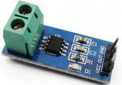
2 针接线端子是载流线应穿过的位置。模块工作在+5V,因此Vcc应由5V供电,接地应连接到系统的地。Vout引脚的失调电压为2500mV,这意味着当没有电流流过导线时,输出电压将为2500mV,当电流为正时,电压将大于2500mV,当电流为负时,电压将小于2500mV。

我们将使用 PIC 微控制器的 ADC 模块来读取模块的输出电压 (Vout),当没有电流流过导线时,输出电压为 512(2500mV)。当电流以负方向流动时,该值将减小,当电流沿正方向流动时,该值将增加。下表将帮助您了解输出电压和ADC值如何根据流过导线的电流而变化。

微控制器

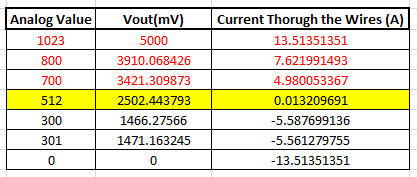
这些值是根据 ACS712 数据表中给出的信息计算得出的。您也可以使用以下公式计算它们:

Vout Voltage(mV) = (ADC Value/  1023)*5000
Current Through the Wire (A) = (Vout(mv)-2500)/185

现在,我们知道了ACS712传感器的工作原理以及我们可以从中得到什么。让我们继续看电路图。

电路图:

下图显示了该数字电流表项目的完整电路图。

微控制器

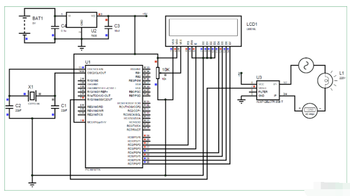
完整的数字电流计电路工作在+5V电压下,由7805稳压器调节。我们使用 16X2 LCD 来显示电流值。电流传感器 (Vout) 的输出引脚连接到 7^千^PIC的引脚,即AN4,用于读取模拟电压。

此外,PIC 的引脚连接如下表所示

S.No: 引脚编号 引脚名称 已连接到
1 21 RD2 液晶显示器的 RS
2 22 RD3 液晶显示器的E
3 27 RD4 液晶屏D4
4 28 RD5 液晶屏D5
5 29 RD6 液晶屏D6
6 30 RD7 液晶屏D7
7 7 AN4 当前塞斯诺的沃特

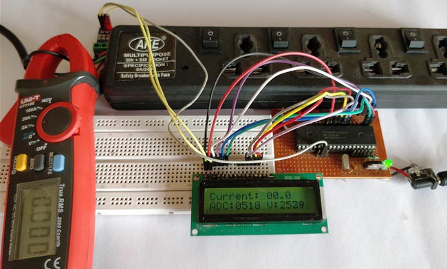
您可以在面包板上构建此数字电流表电路或使用性能板。如果您一直遵循PIC教程,那么您还可以重用我们用于学习PIC微控制器的硬件。在这里,我们使用了与PIC微控制器一起为LED闪烁构建的相同 性能板 ,如下所示:

微控制器

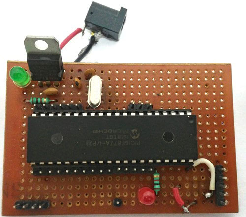
注意: 构建此板不是强制性的,您可以简单地按照电路图在面包板上构建电路,并使用任何转储器套件将程序转储到 PIC 微控制器中。

模拟:

在您实际使用硬件之前,也可以使用 Proteus 模拟此 电流表电路 。分配本教程末尾给出的代码的十六进制文件,然后单击播放按钮。您应该能够注意到LCD显示屏上的电流。我使用灯作为交流负载,您可以通过单击它来改变灯的内阻以改变流过它的电流。

微控制器

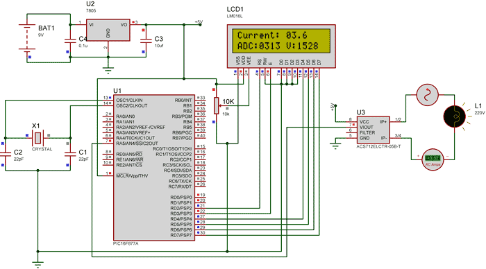
如上图所示,电流表显示流过灯的实际电流约为 3.52 A,LCD 显示电流约为 3.6 A。但是,在实际情况下, 我们可能会得到高达0.2A的误差 。ADC值和电压(mV)也显示在LCD上,供您理解。

PIC微控制器编程:

如前所述,完整的代码可以在本文末尾找到。该代码是用注释行自我解释的,只涉及将LCD与PIC微控制器连接的概念,以及在PIC微控制器中使用ADC模块的概念,我们已经在之前的PIC微控制器学习教程中介绍过。

从传感器读取的值将不准确,因为电流是交流的并且还受到噪声的影响。因此,我们读取ADC值20次并将其平均以获得适当的电流值,如下面的代码所示。

我们使用上面解释的相同公式来计算电压和电流值。

for (int i=0; i<20;i++) //Read value for 20 Times
        {
        adc=0;     
        adc=ADC_Read(4); //Read ADC
        Voltage = adc*4.8828; //Calculate the Voltage
       
        if (Voltage>=2500) //If the current is positive
              Amps += ((Voltage-2500)/18.5);
       
        else if (Voltage<=2500) //If the current is negative
              Amps += ((2500-Voltage)/18.5);
        }

        Amps/=20;  //Average the value that was read for 20 times

由于该项目也可以读取交流电流,因此电流也将是负的和正的。也就是说,输出电压值将高于和低于2500mV。因此,如下图所示,我们更改了负电流和正电流的公式,以便我们不会得到负值。

if (Voltage>=2500) //If the current is positive
              Amps += ((Voltage-2500)/18.5);
       
        else if (Voltage<=2500) //If the current is negative
              Amps += ((2500-Voltage)/18.5);

使用 30A 电流传感器:

如果您需要测量超过 5A 的电流,您可以简单地购买 ACS712-30A 模块并以相同的方式连接它,并通过将 18.5 替换为 0.66 来更改以下代码行,如下所示:

if (Voltage>=2500) //If the current is positive
              Amps += ((Voltage-2500)/0.66);

        else if (Voltage<=2500) //If the current is negative
              Amps += ((2500-Voltage)/0.66);

如果要测量低电流,还可以使用AVR微控制器检查100mA电流表

加工:

一旦您对PIC微控制器进行了编程并准备好了硬件。只需打开负载和PIC微控制器的电源,您应该能够看到电流通过LCD屏幕上显示的电线。

注意: 如果您使用的是 ASC7125A 模块,请确保您的负载消耗不超过 5A,同时使用更高规格的导线作为载流导体。

微控制器

/*

Digital Ammeter for PIC16F877A

 * Code by: B.Aswinth Raj

 * Dated: 27-07-2017

 * More details at: www.CircuitDigest.com

 */


#define _XTAL_FREQ 20000000

#define RS RD2

#define EN RD3

#define D4 RD4

#define D5 RD5

#define D6 RD6

#define D7 RD7


#include 


#pragma config FOSC = HS        // Oscillator Selection bits (HS oscillator)

#pragma config WDTE = OFF       // Watchdog Timer Enable bit (WDT disabled)

#pragma config PWRTE = ON       // Power-up Timer Enable bit (PWRT enabled)

#pragma config BOREN = ON       // Brown-out Reset Enable bit (BOR enabled)

#pragma config LVP = OFF        // Low-Voltage (Single-Supply) In-Circuit Serial Programming Enable bit (RB3 is digital I/O, HV on MCLR must be used for programming)

#pragma config CPD = OFF        // Data EEPROM Memory Code Protection bit (Data EEPROM code protection off)

#pragma config WRT = OFF        // Flash Program Memory Write Enable bits (Write protection off; all program memory may be written to by EECON control)

#pragma config CP = OFF         // Flash Program Memory Code Protection bit (Code protection off)


//LCD Functions Developed by Circuit Digest.

void Lcd_SetBit(char data_bit) //Based on the Hex value Set the Bits of the Data Lines

{

if(data_bit& 1) 

D4 = 1;

else

D4 = 0;


if(data_bit& 2)

D5 = 1;

else

D5 = 0;


if(data_bit& 4)

D6 = 1;

else

D6 = 0;


if(data_bit& 8) 

D7 = 1;

else

D7 = 0;

}


void Lcd_Cmd(char a)

{

RS = 0;           

Lcd_SetBit(a); //Incoming Hex value

EN  = 1;         

        __delay_ms(4);

        EN  = 0;         

}


void Lcd_Clear()

{

Lcd_Cmd(0); //Clear the LCD

Lcd_Cmd(1); //Move the curser to first position

}


void Lcd_Set_Cursor(char a, char b)

{

char temp,z,y;

if(a== 1)

{

 temp = 0x80 + b - 1; //80H is used to move the curser

z = temp>>4; //Lower 8-bits

y = temp & 0x0F; //Upper 8-bits

Lcd_Cmd(z); //Set Row

Lcd_Cmd(y); //Set Column

}

else if(a== 2)

{

temp = 0xC0 + b - 1;

z = temp>>4; //Lower 8-bits

y = temp & 0x0F; //Upper 8-bits

Lcd_Cmd(z); //Set Row

Lcd_Cmd(y); //Set Column

}

}


void Lcd_Start()

{

  Lcd_SetBit(0x00);

  for(int i=1065244; i<=0; i--)  NOP();  

  Lcd_Cmd(0x03);

__delay_ms(5);

  Lcd_Cmd(0x03);

__delay_ms(11);

  Lcd_Cmd(0x03); 

  Lcd_Cmd(0x02); //02H is used for Return home -> Clears the RAM and initializes the LCD

  Lcd_Cmd(0x02); //02H is used for Return home -> Clears the RAM and initializes the LCD

  Lcd_Cmd(0x08); //Select Row 1

  Lcd_Cmd(0x00); //Clear Row 1 Display

  Lcd_Cmd(0x0C); //Select Row 2

  Lcd_Cmd(0x00); //Clear Row 2 Display

  Lcd_Cmd(0x06);

}


void Lcd_Print_Char(char data)  //Send 8-bits through 4-bit mode

{

   char Lower_Nibble,Upper_Nibble;

   Lower_Nibble = data&0x0F;

   Upper_Nibble = data&0xF0;

   RS = 1;             // => RS = 1

   Lcd_SetBit(Upper_Nibble>>4);             //Send upper half by shifting by 4

   EN = 1;

   for(int i=2130483; i<=0; i--)  NOP(); 

   EN = 0;

   Lcd_SetBit(Lower_Nibble); //Send Lower half

   EN = 1;

   for(int i=2130483; i<=0; i--)  NOP();

   EN = 0;

}


void Lcd_Print_String(char *a)

{

int i;

for(i=0;a[i]!='\\0';i++)

  Lcd_Print_Char(a[i]);  //Split the string using pointers and call the Char function 

}

/*****End of LCD Functions*****/


//**ADC FUnctions***//

void ADC_Initialize()

{

  ADCON0 = 0b01000001; //ADC ON and Fosc/16 is selected

  ADCON1 = 0b11000000; // Internal reference voltage is selected

}


unsigned int ADC_Read(unsigned char channel)

{

  ADCON0 &= 0x11000101; //Clearing the Channel Selection Bits

  ADCON0 |= channel<<3; //Setting the required Bits

  __delay_ms(2); //Acquisition time to charge hold capacitor

  GO_nDONE = 1; //Initializes A/D Conversion

  while(GO_nDONE); //Wait for A/D Conversion to complete

  return ((ADRESH<<8)+ADRESL); //Returns Result

}

//***End of ADC Functions***//


int main()

{

    int adc=0; //Variable to read ADC value

    int a1,a2,a3,a4; //Variable to split ADC value into char


    int Voltage; //Variable to store voltage

    int vl1,vl2,vl3,vl4; //Variable to split Voltage value into char


    int Amps; //Variable to store Amps value

    int Am1,Am2,Am3,Am4; //Variable to split Amps value into char


    TRISD = 0x00; //PORTD declared as output for interfacing LCD

    TRISA4 =1; //AN4 declared as input

    ADC_Initialize();

    Lcd_Start();

    Lcd_Clear();


    while(1)

    { 

        /***Current Calculation*****/

        for (int i=0; i<20;i++) //Read value for 20 Times

        {

        adc=0;      

        adc=ADC_Read(4); //Read ADC

        Voltage = adc*4.8828; //Calculate the Voltage


        if (Voltage>=2500) //If the current is positive

              Amps += ((Voltage-2500)/18.5);


        else if (Voltage<=2500) //If the current is negative

              Amps += ((2500-Voltage)/18.5);

        } 

        Amps/=20;  //Average the value that was read for 20 times

        /******Current Calculation******/


        //**Display current**//

        Am1 = (Amps/100)%10;

        Am2 = (Amps/10)%10;

        Am3 = (Amps/1)%10;

        Lcd_Set_Cursor(1,1);

        Lcd_Print_String("Current: ");

        Lcd_Print_Char(Am1+'0');

        Lcd_Print_Char(Am2+'0');

        Lcd_Print_Char('.');

        Lcd_Print_Char(Am3+'0');


         //**Display ADC**//

        a1 = (adc/1000)%10;

        a2 = (adc/100)%10;

        a3 = (adc/10)%10;

        a4 = (adc/1)%10;

        Lcd_Set_Cursor(2,1);

        Lcd_Print_String("ADC:");

        Lcd_Print_Char(a1+'0');

        Lcd_Print_Char(a2+'0');

        Lcd_Print_Char(a3+'0');

        Lcd_Print_Char(a4+'0');


      //**Display Voltage**//

        vl1 = (Voltage/1000)%10;

        vl2 = (Voltage/100)%10;

        vl3 = (Voltage/10)%10;

        vl4 = (Voltage/1)%10;

        Lcd_Print_String(" V:");

        Lcd_Print_Char(vl1+'0');

        Lcd_Print_Char(vl2+'0');

        Lcd_Print_Char(vl3+'0');

        Lcd_Print_Char(vl4+'0');


    }

    return 0;

}
打开APP阅读更多精彩内容
声明:本文内容及配图由入驻作者撰写或者入驻合作网站授权转载。文章观点仅代表作者本人,不代表电子发烧友网立场。文章及其配图仅供工程师学习之用,如有内容侵权或者其他违规问题,请联系本站处理。 举报投诉

全部0条评论

快来发表一下你的评论吧 !

×
20
完善资料,
赚取积分