
基于Arduino的实时人脸检测和跟踪机器人
描述
曾经想过通过简单地使用 Arduino 而不是任何其他编程(如 OpenCV、视觉基础 C# 等)来构建面部跟踪机械臂或机器人吗?然后继续阅读,在这个项目中,我们将通过融合Arduino和Android的强大功能来实现人脸检测。在这个项目中,移动相机将在伺服系统的帮助下随着你的脸一起移动。在这里使用Android手机的优势在于,您无需投资摄像头模块,整个图像检测工作可以在手机本身中完成,您不需要将Arduino连接到计算机即可正常工作。在这里,我们使用蓝牙模块与Arduino进行无线通信。
本项目中使用的Android应用程序是使用处理Android创建的,您可以通过下载APK文件直接安装该应用程序(进一步阅读链接),或者戴上编程帽,使用教程中进一步给出的处理代码制作自己的更具吸引力的Android应用程序。
在本教程结束时,您将拥有一个迷你倾斜和跨度机械臂,可以跟踪您的脸部并随之移动。您可以使用它(进一步发展)来录制您的视频博客视频,甚至可以使用手机的后置摄像头自拍,因为它将您的脸正好定位在手机屏幕的中心。所以!!听起来很有趣?检查本教程末尾的演示视频以查看其工作情况。让我们看看如何构建一个...
我已经尽力使这个项目尽可能简单,任何对硬件或编码有最少知识的人都可以使用此指南使这个项目立即工作。但是,一旦你做到了,我建议你落后于代码,这样你就可以真正知道是什么让这个东西工作以及如何工作。

所需材料:
- Arduino Nano
- 伺服电机 SG90 – 2Nos
- 安卓手机与体面的相机
- HC-05/HC-06 蓝牙模块
- 编程计算机
- 3D打印机(可选)
- 9V电池
3D 打印所需部件(可选):
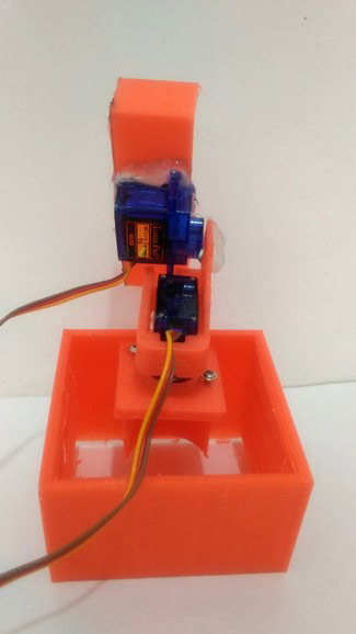
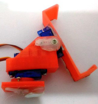
为了平移和倾斜我们的手机,我们需要一些机械结构,如移动支架和一些伺服支架。你可以用纸板做一个,因为我有一台3D打印机,我决定3D打印这些零件。
3D打印是一个了不起的工具,在构建原型项目或试验新的机械设计时可以做出很多贡献。如果您还没有发现3D打印机的好处或它是如何工作的,你可以阅读3D打印初学者指南。
如果您拥有或可以使用3D打印机,则可以使用可以从此处下载的STL文件直接打印和组装它们。但是,像手机支架这样的一些部件可能需要根据手机的尺寸进行一些修改。我为我的MOTO G手机设计了它。我使用我的一台非常基本的打印机来打印所有零件。打印机是来自3ding的FABX v1,价格实惠,打印量为10立方厘米。便宜的价格伴随着低打印分辨率和没有SD卡或打印恢复功能的权衡。我正在使用名为Cura的软件来打印STL文件。下面给出了我用于打印材料的设置,您可以使用相同的设置或根据您的打印机更改它们。

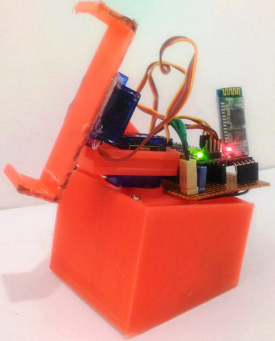
打印所有必需的材料后,您可以使用螺钉和一些热胶将它们固定到位。组装完成后,它应该如下所示。


原理图和硬件:
此智能手机面部跟踪项目的电路如下图所示:
该电路由两个伺服电机组成,其中一个用于向左/向右移动手机,另一个用于向上/向下倾斜手机。伺服器必须移动的方向将由Arduino Nano指示,Arduino Nano本身从蓝牙(HC-05)模块获取信息。整个电路由9V电池供电。
该电路可以很容易地连接到您的面包板上,或者您也可以像我在这里所做的那样将它们焊接在小型 Perf 板上。
设置您的安卓应用程序:
正如我之前所说,这个项目背后的主要大脑是这个Android应用程序。这个安卓应用程序是使用处理安卓开发的。您可以直接在手机上安装此应用程序,然后按照以下步骤启动它。
- 从这里下载APK文件。
- 打开上面显示的电路的电源。
- 在手机设置中搜索名为“HC-05”的蓝牙模块
- 如果您将其命名为“HC-05”以外的其他名称,请将其更改回HC-05,因为只有这样应用程序才能工作。
- 使用密码“1234”或“0000”与您的蓝牙模块配对。
- 现在,以纵向模式启动应用程序。您应该会看到相机屏幕,并在屏幕顶部看到“连接到:HC-05”。
- 尝试将相机移到脸部上方,其顶部应会出现一个绿色框,其位置也将显示在屏幕的左上角,如下所示。

您可以通过引入许多不需要编写自己的Android应用程序即可获得的进步,从而将这个Arduino面部跟踪项目提升到一个新的水平。创建一个Android应用程序可能听起来很困难,但相信我,在Processing的帮助下,您可以立即学习它。
对 Arduino 进行编程:
安卓应用程序将检测人脸及其在屏幕上的位置;然后,它将根据面部的位置决定应该移动的方向,以便面部到达屏幕中心。然后通过蓝牙模块将此方向发送到Arduino。
该项目的Arduino程序相当简单,我们只需要根据从蓝牙模块接收的值控制两个伺服电机的方向。完整的代码可以在本教程的末尾找到,我还在下面解释了几个重要的行。
下面的代码行建立串行连接,引脚 D12 作为 RX,D11 作为 TX。因此,引脚 D12 必须连接到 BT 模块的 TX,引脚 D11 必须连接到 BT 模块的 RX。
SoftwareSerial cam_BT(12, 11); // RX, TX
然后我们以 9600 的波特率初始化蓝牙模块.确保您的模块也以相同的波特率工作。否则相应地更改它。
cam_BT.begin(9600); //start the Bluetooth communication at 9600 baudrate
cam_BT.println("Ready to take commands");
下面一行读取通过蓝牙模块传入的内容.此外,数据保存在变量“蓝牙数据”中。
if (cam_BT.available()) //Read whats coming in through Bluetooth
   {
BluetoothData=cam_BT.read();
Serial.print("Incoming from BT:");
Serial.println(BluetoothData);
}
根据从蓝牙接收的数据,控制电机方向。要向左转动电机,电机会从其先前的位置递减 2 的值。如果您需要手臂移动得更快,您可以将此值增加到 4 或 6。但是,它可能会产生一些颠簸,使相机不稳定。
if (BluetoothData==49) //Turn Left
{pos1+=2; servo1.write(pos1);}

if (BluetoothData==50) //Turn Right
{pos1-=2; servo1.write(pos1);}

if (BluetoothData==51) //Turn Up
{pos2-=2; servo2.write(pos2);}

if (BluetoothData==52) //Turn Down
{pos2+=2; servo2.write(pos2);}
加工:
一旦我们准备好了我们的硬件,代码和Android应用程序,就该采取一些行动了。只需为您的 Arduino 供电并打开安卓应用程序。应用程序将自动连接到 HC-05 (必须命名为 HC-05) 蓝牙模块,并等待检测到人脸.只需将手机放在我们的手机支架中并坐在它前面即可。您应该注意到伺服电机移动手机,以便将脸部放置在屏幕中央。现在在相机的范围内四处走动,您的手机将跟随您的动作。您也可以通过放置和移动任何图片来尝试。

/*Arduino Code for Face Tracking Arduino

 * Coded by Circuitdigest.com

 * On 25-05-2017

 */


 /*CONNECTION DETIALS

  * Arduino D11 -> RX of BT Module

  * Arduino D12 -> Tx of BT

  * Servo1 -> pin 3 of arduino Nano to pan

  * Servo2 -> pin 5 of arduino Nano to tilt

  */


#include  //header to drive servo motors

#include // import the serial library

SoftwareSerial cam_BT(12, 11);  // RX, TX

int ledpin=13; // led on D13 will show blink on / off

int BluetoothData; // the data given from Computer


//lets declare the servo objects

Servo servo1;

Servo servo2;


long gmotor,gnum1,gnum2;

int pos;

int flag=0;

int pos1 = 40;

int pos2 = 90;


void setup() {

   servo1.attach(3);

   servo2.attach(5);;


   //**Initial position of all four servo motors**//

   servo1.write(pos1);

   servo2.write(pos2);

   //**initialised**//


cam_BT.begin(9600); //start the Bluetooth communication at 9600 baudrate

cam_BT.println("Ready to take commands");


Serial.begin(57600);

Serial.println("Face tracking programming by CircuitDigest.com");

}


//***Function for each Servo actions**//

void call(int motor, int num1, int num2) // The values like Motor number , from angle and to angle are received

{

Serial.println("Passing values...");

flag =0;

switch (motor)

  {

    case 1:            // For motor one

    {

    Serial.println("Executing motor one");

    if(num1// Clock wise rotation

    {

        for ( pos =num1; pos<=num2; pos+=1)

            {

            servo1.write(pos);

            delay( 20);

            }

    }


    if(num1>num2) // Anti-Clock wise rotation

    {

        for ( pos =num1; pos>=num2; pos-=1)

        {

        servo1.write(pos);

        delay( 20);

        }

    }

     break;

    }


       ////////JUST  DUPLICATE FOR OTHER SERVOS////


    case 2:    // For motor 2

    {

    Serial.println("Executing motor two");

    if(num1for ( pos =num1; pos<=num2; pos+=1)

        {

        servo2.write(pos);

        delay( 20);

        }

    }

    if(num1>num2)

    {

        for ( pos =num1; pos>=num2; pos-=1)

        {

        servo2.write(pos);

        delay( 20);

        }

    }

    break;

    }

  }

}


void loop() {

 if(Serial.available()>0) //Read whats coming in through Serial

  {

  gmotor= Serial.parseInt();

  Serial.print(" selected Number-> ");

  Serial.print(gmotor);

  Serial.print(" , ");

  gnum1= Serial.parseInt();

  Serial.print(gnum1);

  Serial.print(" degree , ");

  gnum2= Serial.parseInt();

  Serial.print(gnum2);

  Serial.println(" degree ");

  flag=1;

  }


 if (cam_BT.available()) //Read whats coming in through Bluetooth

 {

  BluetoothData=cam_BT.read();

  Serial.print("Incoming from BT:");

  Serial.println(BluetoothData);

 }


 if (flag ==1)

 call(gmotor,gnum1,gnum2); //call the respective motor for action


 if (BluetoothData==49) //Turn Left

 {pos1+=2; servo1.write(pos1);}


 if (BluetoothData==50) //Turn Right

 {pos1-=2; servo1.write(pos1);}


 if (BluetoothData==51) //Turn Up

 {pos2-=2; servo2.write(pos2);}


 if (BluetoothData==52) //Turn Down

 {pos2+=2; servo2.write(pos2);}


 flag=0;

 BluetoothData=0;

}
-
 jf_65337762
2023-04-22
1 回复 举报那么应用程序在哪里下载呢 收起回复
-
RK3576机器人核心:三屏异显+八路摄像头,重塑机器人交互与感知2025-10-29 647
-
【mBot申请】基于Nao机器人的视觉跟踪处理2015-10-29 3444
-
自律型机器人制作入门.基于Arduino2016-06-23 5390
-
旧手机 Arduino的巅峰之作—视频监控机器人 ,异地远程遥控2016-09-27 9645
-
Arduino机器人制作指南2017-06-14 4486
-
焊缝跟踪:自动化机器人实时焊缝跟踪寻位2019-04-19 1439
-
焊缝跟踪:机器人焊缝跟踪系统的优势分析2019-04-29 3027
-
焊缝跟踪:焊接机器人配焊缝跟踪传感器是科技发展的必然趋势2019-08-01 1277
-
在黑暗里机器人怎么识别人脸?2019-09-17 2804
-
家庭智能小管家机器人资料分享!2019-10-09 3525
-
使用旅游机器人需要注意哪些问题?2020-06-12 3048
-
微信控制的家庭智能机器人(附语音聊天、人脸检测、自主巡航等)2020-09-30 3672
-
构建ARLOK arduino机器人的教程2022-08-08 1531
-
Arduino教学机器人的使用教程2023-09-27 651
-
实时车辆检测和跟踪系统设计2010-03-03 752
全部0条评论

快来发表一下你的评论吧 !


