

【产品应用】AWorksLP 样例详解(MR6450)—— HWTimer
电子说
1.4w人已加入
描述

 简介
简介延时型硬件定时器: 由硬件定时器外设提供的延时功能。
计数型硬件定时器: 提供较精确的类似时间戳的功能。
周期型硬件定时器: 可设置中断频率的计数器,不仅能提供计数器的功能,也能根据中断频率提供更精确的定时。
输入捕获定时器: 可测量脉冲宽度或者测量频率。
 接口介绍
接口介绍 使用样例
使用样例/**
* rief 硬件定时器中断服务函数。
* param[in] p_arg : 任务参数
*/
static void mytimer_isr (void *p_arg)
{
aw_gpio_toggle((int)p_arg);
aw_kprintf("enter isr
");
}
/**
* rief hwtimer 测试函数
*/
aw_local void* __task_handle (void *arg)
{
int fd;
aw_err_t ret;
uint32_t count = 5;
aw_hwtimer_rate_t p_intr_freq;
p_intr_freq.rate_denominator = 5;
p_intr_freq.rate_numerator = 1;
fd = aw_open(CONFIG_DEMO_HWTIMER_PEROID_DEV_NAME, AW_O_RDWR, 0);
if (fd < 0) {
aw_kprintf("hwtimer open failed:%d
", fd);
while(1);
}
ret = aw_hwtimer_period_intr_freq_set_frac(fd, &p_intr_freq);
while (count) {
aw_hwtimer_period_wait(fd, 500);
mytimer_isr(arg);
count --;
}
// 配置每秒中断2次
ret = aw_hwtimer_period_intr_freq_set(fd, 2);
ret = aw_hwtimer_period_start(fd);
if (ret != AW_OK) {
aw_kprintf("Timer allocation fail!
");
}
ret = aw_hwtimer_period_wait(fd, AW_WAIT_FOREVER);
while (1) {
aw_hwtimer_period_wait(fd, AW_WAIT_FOREVER);
mytimer_isr(arg);
}
for (;;) {
aw_mdelay(1000);
}
aw_close(fd);
return 0;
}下表为使用硬件周期型定时器,在中断中进行引脚翻转,通过逻辑分析仪所测量出的实际数据,在使用设计时可作为部分参考依据。

aw_local void* __task_handle (void *arg)
{
    uint32_t     count = 0;
    int          fd, led_fd;
    int          ret;
    uint32_t     start_count;

    fd = aw_open(CONFIG_DEMO_HWTIMER_PEROID_DEV_NAME, AW_O_RDWR, 0);
    if (fd < 0) {
        aw_kprintf("hwtimer open fail! :%d
",fd);
        return;
    }
    /* 打开设备会点亮LED */
    led_fd = aw_open("/dev/led_run", AW_O_RDWR, 0);
    if (led_fd < 0) {
        aw_kprintf("led open fail! :%d
", led_fd);
        aw_close(fd);
        return;
    }
    ret = aw_hwtimer_count_rate_get(fd, &start_count);
    if (ret != AW_OK) {
        aw_kprintf("Timer count rate get fail!
");
        aw_close(fd);
        aw_close(led_fd);
        return;
    }
    // 设置时钟频率
    ret = aw_hwtimer_count_rate_set(fd, start_count/2);
    if (ret != AW_OK) {
        aw_kprintf("Timer count rate set fail!
");
        aw_close(fd);
        aw_close(led_fd);
        return;
    }
    ret = aw_hwtimer_count_start(fd);
    if (ret != AW_OK) {
        aw_kprintf("Timer start fail!
");
        aw_close(fd);
        aw_close(led_fd);
        return;
    }
    for (;;) {
        aw_led_toggle(led_fd);
        aw_mdelay(500);
        aw_led_toggle(led_fd);
        aw_hwtimer_count_get(fd, &count);
        aw_kprintf("Count is %d
", count);
    }
    aw_close(fd);
    aw_close(led_fd);
    return 0;
}
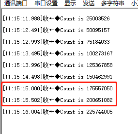

aw_local void* __task_handle (void *arg)
{
    int                 i;
    int                 fd;
    aw_err_t            ret;
    aw_timespec_t       timespec;
    aw_timestamp_t      start_timestamp, stop_timestamp;
    aw_timestamp_freq_t timestamp_freq;
    uint64_t            delay_ns, diff;
    uint32_t            ns_numerator = 1000000000;


    timestamp_freq = aw_timestamp_freq_get();
    while (0 == (timestamp_freq % 10)) {
        timestamp_freq /= 10;
        ns_numerator /= 10;
}


    fd = aw_open(CONFIG_DEMO_HWTIMER_DELAY_DEV_NAME, AW_O_RDWR, 0);
    if (fd < 0) {
        aw_kprintf("hwtimer open failed:%d

", fd);
        while(1);
    }


    delay_ns = 2001000;
    for (i = 0; i < 100; i++) {
        timespec.tv_sec = delay_ns / 1000000000u;
        timespec.tv_nsec = (uint32_t)(delay_ns % 1000000000u);


        start_timestamp = aw_timestamp_get();
        ret = aw_hwtimer_delay(fd, ×pec);
        if (ret !=AW_OK) {
            aw_kprintf("hwtimer delay failed:%d

", ret);
        }
        aw_barrier();
        stop_timestamp = aw_timestamp_get();


        stop_timestamp -= start_timestamp;
        diff = stop_timestamp;
        diff *= ns_numerator;
        diff /= timestamp_freq;


        diff = diff - delay_ns;
        aw_kprintf(
                "hwtimer_delay delay = %u,diff = %u ns
",
                (uint32_t)delay_ns,
                (uint32_t)diff);
        delay_ns += 100000;
    }
    aw_close(fd);
    return 0;
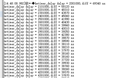
}
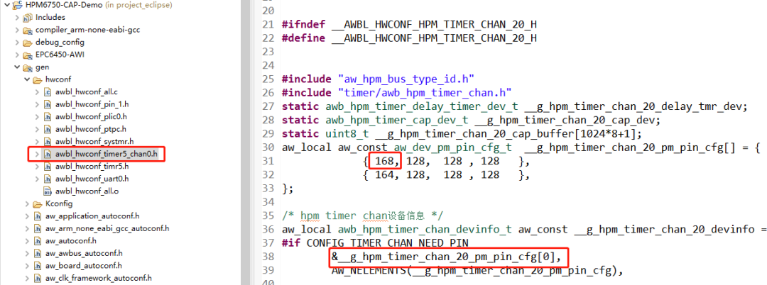
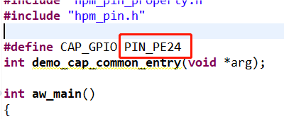
{SDK}demosperipheralcap路径下为捕获型定时器例程,例程关键代码如下:
/* 单边沿触发*/
static void test_cap_single_edge(
int fd,
int gpio_cap,
uint32_t ms,
aw_hwtimer_cap_config_t *p_config,
int is_rising)
{
uint64_t cap_val1, cap_val2;
aw_err_t ret;
// 制造两次上升沿
mk_edge(gpio_cap, 5);
aw_task_delay(ms);
mk_edge(gpio_cap, 5);
// 此时应该产生了两次捕获事件
// 把它们读出来
ret = aw_hwtimer_cap_read(fd, &cap_val1, AW_WAIT_FOREVER);
if (AW_OK != ret) {
aw_kprintf("cap read cap_val1 failed
");
return;
}
ret = aw_hwtimer_cap_read(fd, &cap_val2, AW_WAIT_FOREVER);
if (AW_OK != ret) {
aw_kprintf("cap read cap_val2 failed
");
return;
}
cap_val2 -= cap_val1;
cap_val2 *= 1000000;
cap_val2 /= p_config->sample_rate;
if (is_rising) {
aw_kprintf("two rising edge between %u ms
", ms + 5);
}
else {
aw_kprintf("two falling edge between %u ms
", ms + 5);
}
aw_kprintf("two capture events between %llu us
", cap_val2);
}
static void demo_cap_base(int gpio_cap)
{
int fd;
aw_err_t ret;
aw_hwtimer_cap_config_t config;
// 使得测试GPIO输出为0
aw_gpio_set(gpio_cap, 0);
fd = aw_open(CONFIG_DEMO_HWTIMER_CAP_DEV_NAME, AW_O_RDWR, 0);
if (fd < 0) {
aw_kprintf("cap open failed!
");
return;
}
// 获取捕获定时器的配置
ret = aw_hwtimer_cap_config_get(fd, &config);
if (ret != AW_OK) {
aw_kprintf("cap config get failed...
");
aw_close(fd);
return ;
}
int is_rising;
// 配置为上升沿触发捕获
config.cap_edge_flags = AW_CAPTURE_RISING_EDGE;
is_rising = 1;
ret = aw_hwtimer_cap_config_set(fd, &config);
if (ret != AW_OK) {
aw_kprintf("cap config set failed...
");
aw_close(fd);
return ;
}
ret = aw_hwtimer_cap_start(fd);
if (ret != AW_OK) {
aw_kprintf("cap start failed...
");
aw_close(fd);
return ;
}
test_cap_single_edge(fd, gpio_cap, 20, &config, is_rising);
aw_close(fd);
}




至此,所有类型的硬件定时器样例均已展示完毕,在软件应用设计中可根据实际需求选取不同类型的定时器进行使用。更多其他类型外设的用法介绍,请关注后续同系列推文~




原文标题:【产品应用】AWorksLP 样例详解(MR6450)—— HWTimer
文章出处:【微信公众号:ZLG致远电子】欢迎添加关注!文章转载请注明出处。
声明:本文内容及配图由入驻作者撰写或者入驻合作网站授权转载。文章观点仅代表作者本人,不代表电子发烧友网立场。文章及其配图仅供工程师学习之用,如有内容侵权或者其他违规问题,请联系本站处理。
举报投诉
- 相关推荐
- 热点推荐
- 致远电子
-
AWorksLP 样例详解(MR6750)——双核调试2023-09-23 1105
-
AWorksLP 样例详解(MR6750)——双核烧录2023-09-21 1222
-
【产品应用】AWorksLP例程介绍(MR6450)—— SD卡2023-05-10 1206
-
EPC6450-AWI工控板搭载MR6450核心板,强势来袭!2023-02-23 1473
-
【产品应用】AWorksLP 样例详解(MR6450)—— HWTimer2023-02-02 1250
-
【产品应用】AWorksLP 样例详解(MR6450)——PWM(单通道)2023-01-04 1024
-
【产品应用】AWorksLP 样例详解(MR6450)——UART2022-12-23 1249
-
【产品应用】AWorksLP样例详解(MR6450)-- GPIO2022-12-16 1140
-
【产品应用】AWorksLP SDK快速入门(MR6450)——开箱体验2022-12-09 1152
-
【深度解析】MR6450系列RISC-V核心板究竟有哪些过人之处?2022-12-05 1280
全部0条评论

快来发表一下你的评论吧 !

