

KITTI数据集解读络!
描述
1.KITTI数据集概述
KITTI数据集由德国卡尔斯鲁厄理工学院和丰田美国技术研究院联合创办,是目前国际上最大的自动驾驶场景下的计算机视觉算法评测数据集。
该数据集用于评测立体图像(stereo),光流(optical flow),视觉测距(visual odometry),3D物体检测(object detection)和3D跟踪(tracking)等计算机视觉技术在车载环境下的性能。
KITTI包含市区、乡村和高速公路等场景采集的真实图像数据,每张图像中最多达15辆车和30个行人,还有各种程度的遮挡与截断。整个数据集由389对立体图像和光流图,39.2 km视觉测距序列以及超过200k 3D标注物体的图像组成[1] ,以10Hz的频率采样及同步。
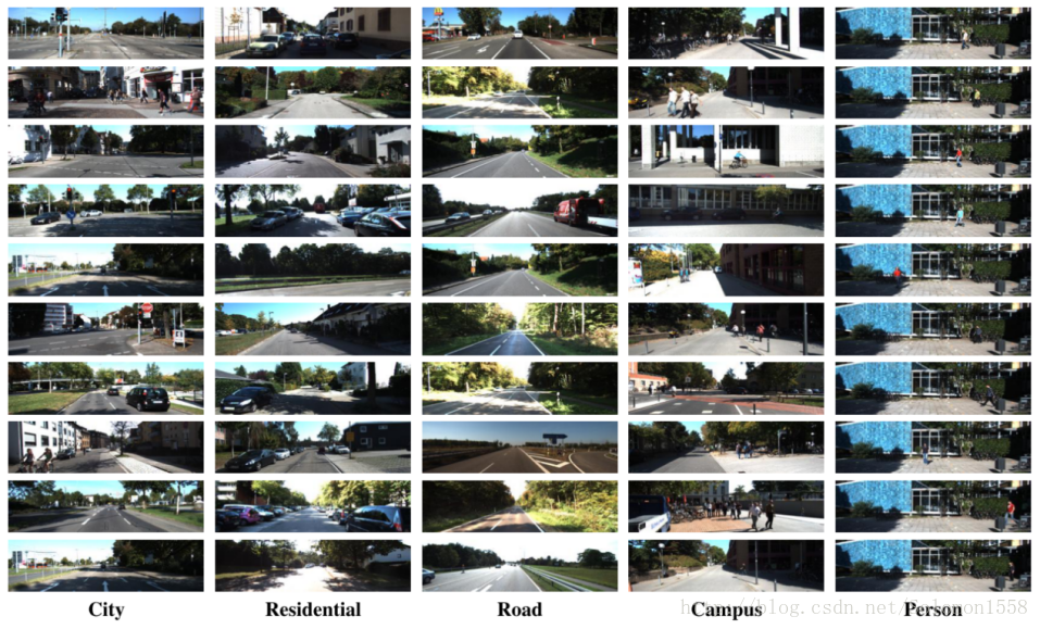
总体上看,原始数据集被分类为’Road’, ’City’, ’Residential’, ’Campus’ 和 ’Person’。对于3D物体检测,label细分为car, van, truck, pedestrian, pedestrian(sitting), cyclist, tram以及misc组成。
地址: http://www.cvlibs.net/datasets/kitti
相关论文:
1、Geiger A, Lenz P, Urtasun R. Are we ready for autonomous driving? the kitti vision benchmark suite[C]//2012 IEEE Conference on Computer Vision and Pattern Recognition. IEEE, 2012: 3354-3361.
2、Geiger A, Lenz P, Stiller C, et al. Vision meets robotics: The kitti dataset[J]. The International Journal of Robotics Research, 2013, 32(11): 1231-1237.
3、Uhrig J, Schneider N, Schneider L, et al. Sparsity invariant cnns[C]//2017 international conference on 3D Vision (3DV). IEEE, 2017: 11-20.
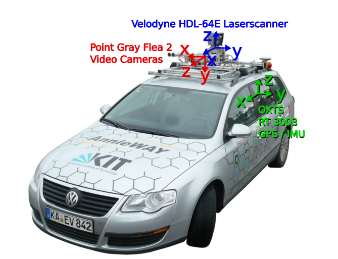
2.数据采集平台
如图-1所示,KITTI数据集的数据采集平台装配有2个灰度摄像机,2个彩色摄像机,一个Velodyne 64线3D激光雷达,4个光学镜头,以及1个GPS导航系统。
具体的传感器参数如下[2] :
- 2 × PointGray Flea2 grayscale cameras (FL2-14S3M-C), 1.4 Megapixels, 1/2” Sony ICX267 CCD, global shutter
-
2 × PointGray Flea2 color cameras (FL2-14S3C-C), 1.4 Megapixels, 1/2” Sony ICX267 CCD, global shutter
-
4 × Edmund Optics lenses, 4mm, opening angle ∼ 90◦, vertical opening angle of region of interest (ROI) ∼ 35◦
-
1 × Velodyne HDL-64E rotating 3D laser scanner, 10 Hz, 64 beams, 0.09 degree angular resolution, 2 cm distance accuracy, collecting ∼ 1.3 million points/second, field of view: 360◦ horizontal, 26.8◦ vertical, range: 120 m
-
1 × OXTS RT3003 inertial and GPS navigation system, 6 axis, 100 Hz, L1/L2 RTK, resolution: 0.02m / 0.1◦
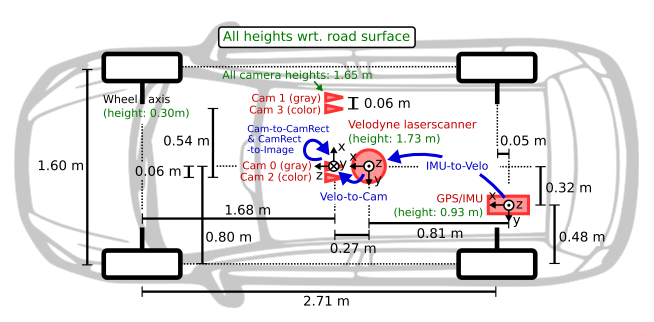
如图-2所示为传感器的配置平面图。为了生成双目立体图像,相同类型的摄像头相距54cm安装。
由于彩色摄像机的分辨率和对比度不够好,所以还使用了两个立体灰度摄像机,它和彩色摄像机相距6cm安装。为了方便传感器数据标定,规定坐标系方向如下[2] :
-
Camera: x = right, y = down, z = forward
-
Velodyne: x = forward, y = left, z = up
-
GPS/IMU: x = forward, y = left, z = up
3.Dataset详述
图-3展示了KITTI数据集的典型样本,分为 ’Road’, ’City’, ’Residential’, ’Campus’ 和’Person’五类。原始数据采集于2011年的5天,共有180GB数据。
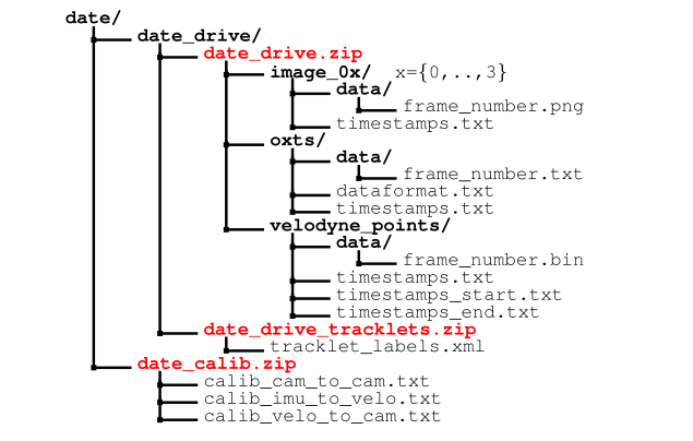
3.1 数据组织形式
论文[2] 中提及的数据组织形式,可能是早期的版本,与目前KITTI数据集官网公布的形式不同,本文稍作介绍。
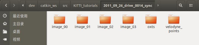
如图-4所示,一个视频序列的所有传感器数据都存储于data_drive文件夹下,其中date和drive是占位符,表示采集数据的日期和视频编号。时间戳记录在Timestamps.txt文件。
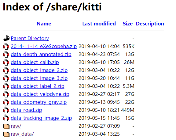
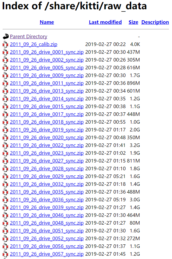
下载地址: 有大神将其放在了自己的服务器方便大家下载, http://dataset.f3322.net:666/share/kitti/
3.2 Development Kit
KITTI各个子数据集都提供开发工具 development kit,主要由cpp文件夹,matlab文件夹,mapping文件夹和readme.txt组成。
下图以object detection任务的文件夹devkit_object为例,可以看到cpp文件夹主要包含评估模型的源代码evaluate_object.cpp。
Mapping文件夹中的文件记录训练集到原始数据集的映射,从而开发者能够同时使用激光雷达点云,gps数据,右边彩色摄像机数据以及灰度摄像机图像等多模态数据。
Matlab文件夹中的工具包含读写标签,绘制2D/3D标注框,运行demo等工具。Readme.txt文件非常重要,详述介绍了某个子数据集的数据格式,benchmark介绍,结果评估方法等详细内容。
devkit_object
|── cpp
│ |── evaluate_object.cpp
│ └── mail.h
|── mapping
│ |── train_mapping.txt
│ └── train_rand.txt
|── matlab
│ |── computeBox3D.m
│ |── computeOrientation3D.m
│ |── drawBox2D.m
│ |── drawBox3D.m
│ |── projectToImage.m
│ |── readCalibration.m
│ |── readLabels.m
│ |── run_demo.m
│ |── run_readWriteDemo.m
│ |── run_statistics.m
│ |── visualization.m
│ └── writeLabels.m
3.3 GPS/IMU位姿数据
OXTS (GPS/IMU):
对于每一帧,我们将30个不同的GPS /IMU值存储在文本文件中:地理坐标包括高度,全球定位,速度,加速度,角速率,精度和卫星信息。加速度和角速率都是使用两个坐标系指定的,一个坐标系与车体(x,y,z)相连,另一个坐标系映射到该位置的地表切面(f,l,U)。
我们偶尔会遇到与OXTS设备短时间(约1秒)的通信中断,我们为此线性插入所有值,并将最后3个条目设置为'-1'以指示缺失的信息。dataformat.txt提供了更多细节。转换实用程序在开发工具包中提供。
主要提供以下30个数值:
- lat: latitude of the oxts-unit (deg)
- lon: longitude of the oxts-unit (deg)
- alt: altitude of the oxts-unit (m)
- roll: roll angle (rad), 0 = level, positive = left side up (-pi…pi)
- pitch: pitch angle (rad), 0 = level, positive = front down (-pi/2…pi/2)
- yaw: heading (rad), 0 = east, positive = counter clockwise (-pi…pi)
- vn: velocity towards north (m/s)
- ve: velocity towards east (m/s)
- vf: forward velocity, i.e. parallel to earth-surface (m/s)
- vl: leftward velocity, i.e. parallel to earth-surface (m/s)
- vu: upward velocity, i.e. perpendicular to earth-surface (m/s)
- ax: acceleration in x, i.e. in direction of vehicle front (m/s^2)
- ay: acceleration in y, i.e. in direction of vehicle left (m/s^2)
- az: acceleration in z, i.e. in direction of vehicle top (m/s^2)
- af: forward acceleration (m/s^2)
- al: leftward acceleration (m/s^2)
- au: upward acceleration (m/s^2)
- wx: angular rate around x (rad/s)
- wy: angular rate around y (rad/s)
- wz: angular rate around z (rad/s)
- wf: angular rate around forward axis (rad/s)
- wl: angular rate around leftward axis (rad/s)
- wu: angular rate around upward axis (rad/s)
- posacc: velocity accuracy (north/east in m)
- velacc: velocity accuracy (north/east in m/s)
- navstat: navigation status
- numsats: number of satellites tracked by primary GPS receiver
- posmode: position mode of primary GPS receiver
- velmode: velocity mode of primary GPS receiver
- orimode: orientation mode of primary GPS receiver
可以利用matlab程序中的oxts = loadOxtsliteData('2011_xx_xx_drive_xxxx')来解析GPS/IMU数据,然后利用pose = convertOxtsToPose(oxts)程序将oxts数据转换为米制单位位姿,用一个4x4的刚体变换矩阵表示。
3.4 传感器标定
这部分内容对于想要利用KITTI中多个传感器数据进行传感器融合相关算法开发至关重要。
raw data数据集中提供了三个标定文件,分别是:
calib_cam_to_cam.txt——相机到相机之间的标定:
-
-S_xx:表示图像矫正前的尺寸——宽 高
-
-K_xx:表示相机xx图像矫正前的标定矩阵,3x3大小
-
-D_xx:矫正前相机xx的1x5畸变向量
-
-R_xx:相机xx的3x3旋转矩阵(相机外参)
-
-T_xx:相机xx的3x1平移向量(相机外参)
-
-S_rect_xx:矫正后相机xx图像尺寸
-
-R_rect_xx:3x3的矫正旋转矩阵用来使图像平面共面
-
-P_rect_xx:矫正后3x4的投影矩阵(表示将矫正后相机00下坐标转到相机xx下图像像素的投影矩阵)
注意: 在使用同步矫正数据集时,我们一般只会用到P_rect_xx矩阵和R_rect_00矩阵。
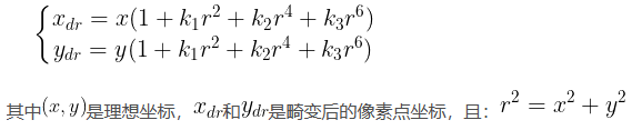
D_xx解释:
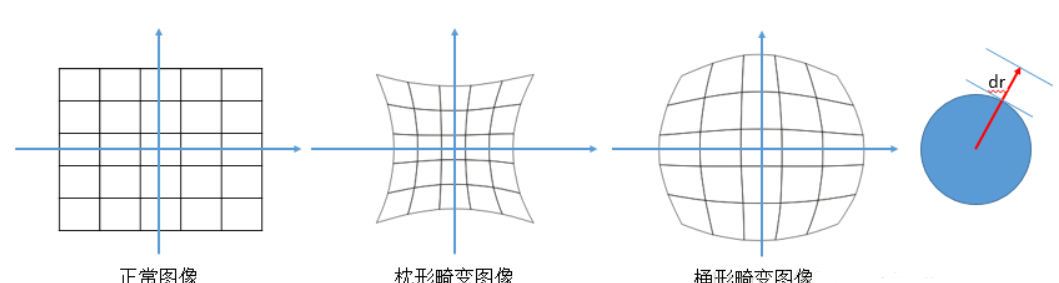
图像的畸变主要有两种:径向畸变和切向畸变。
径向畸变:正中心位置的畸变最小,随着半径的增大,畸变增大。径向畸变可以分为枕形畸变和桶形畸变:
径向畸变矫正公式如下(泰勒级数展开式前3项):
切向畸变:在透镜与成像平面不平行时就会产生,类似于透视变换。
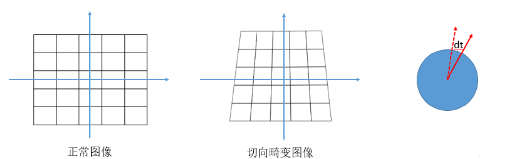
切向畸变的矫正公式如下:

calib_velo_to_cam.txt——激光雷达到相机之间的对准:
-
-R:3x3的旋转矩阵
-
-T:3x1的平移向量
R|T共同组成一个刚体变换矩阵,用来将激光雷达坐标系下的一个点转换到左侧灰度相机(即cam00)坐标系下。在开发激光雷达和相机融合相关算法时会用到。
calib_img_to_velo.txt——GPS/IMU到激光雷达之间的对准:
-
-R:3x3的旋转矩阵
-
-T:3x1的平移向量
3.5 深度预测、深度完成模块的数据介绍
激光数据被保存成png格式(uint16)与真实距离(米)之间的关系:png的像素值除以256,来源:
http://www.cvlibs.net/datasets/kitti/eval_depth_all.php
Download development kit (48 K) 中的 readme.txt(http://www.cvlibs.net/downloads/depth_devkit.zip)
disp(u,v) = ((float)I(u,v))/256.0; valid(u,v) = I(u,v)>0;
KITTI中的3D激光雷达点云(官网下载的raw文件中的sync文件下的)bin文件(infile),转成pcd文件(outfile)存储代码:
// load point cloud
fstream input(infile.c_str(), ios::in | ios::binary);
if(!input.good()){
cerr << "Could not read file: " << infile << endl;
exit(EXIT_FAILURE);
}
input.seekg(0, ios::beg);
pcl::PointCloud::Ptr points (new pcl::PointCloud) ;
int i;
for (i=0; input.good() && !input.eof(); i++) {
PointXYZI point;
input.read((char *) &point.x, 3*sizeof(float));
input.read((char *) &point.intensity, sizeof(float));
points->push_back(point);
}
input.close();
cout << "Read KTTI point cloud with " << i << " points, writing to " << outfile << endl;
pcl::PCDWriter writer;
// Save DoN features
writer.write (outfile, *points, false);
3.6 pose数据介绍
数据集位置:
https://s3.eu-central-1.amazonaws.com/avg-kitti/devkit_odometry.zip
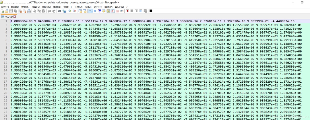
在文件夹 devkit_odometry/devkit/reame.txt 中说明: 在poses目录下,包含00.txt-10.txt 11个序列,每一个文件包换Nx12个表格,N代表帧数。
每一行利用3x4转移矩阵代表左边相机(猜想这里指的是 Cam 0, 左侧的灰度相机)坐标系统的位姿,转移矩阵将当前帧左边相机系统中的一个点映射到第0帧的坐标系统中。转移矩阵中平移的部分表示当前相机位置(相对于第0帧)。
原文: Folder 'poses': The folder 'poses' contains the ground truth poses (trajectory) for the first 11 sequences. This information can be used for training/tuning your method. Each file xx.txt contains a N x 12 table, where N is the number of frames of this sequence. Row i represents the i'th pose of the left camera coordinate system (i.e., z pointing forwards) via a 3x4 transformation matrix. The matrices are stored in row aligned order (the first entries correspond to the first row), and take a point in the i'th coordinate system and project it into the first (=0th) coordinate system. Hence, the translational part (3x1 vector of column 4) corresponds to the pose of the left camera coordinate system in the i'th frame with respect to the first (=0th) frame.
(john解读:ORB-SLAM3中相机位姿(camera pose)的表示是Tcw,即世界坐标系的点Pw到相机坐标系的点Pc的变换矩阵,(camera pose 的逆是Twc, 即 Pw = Twc * Pc)。这里的pose.txt保存时,以第一帧(的相机坐标系)作为世界坐标系(即 0,0,0,0,0,0,1),保存的为第i帧相机坐标系下的点到第0帧(世界坐标系)的变换,即Twc(相机位姿的逆)。
示例:sequence 00 的poses(轨迹)00.txt
审核编辑 :李倩
-
探索 ADAQ23876:16 位、15 MSPS μModule 数据采集解决方案2026-03-27 261
-
ADAQ4224:24位、2 MSPS μModule数据采集解决方案深度解析2026-03-25 302
-
冲压PLC类设备的数据采集解决方案2025-08-07 1047
-
PLC数据采集解决方案2024-10-31 1551
-
网关数据采集解决方案2024-03-08 1707
-
KOYUELEC光与电子提供SUNLORDINC顺络电子数据免费2022-06-07 796
-
凌华科技推出全新MCM-216/218 边缘DAQ数据采集解决方案2021-07-15 5086
-
光洋PLC以太网通讯数据采集解决方案 相关资料推荐2021-07-02 2463
-
求一种PCIe接口的视频采集解决方案2021-04-30 1416
-
UG-1533:评估ADAQ4003 18位2 MSPSµ模块数据采集解决方案2021-03-22 833
-
大华股份AI取得KITTI Sceneflow排行榜第一2020-09-25 3793
-
无人驾驶数据集你只知道Kitti吗?而实际比你想象的多2019-04-22 22640
-
完整传感器数据采集解决方案简化工业数据采集系统设计2016-01-04 878
全部0条评论

快来发表一下你的评论吧 !
