

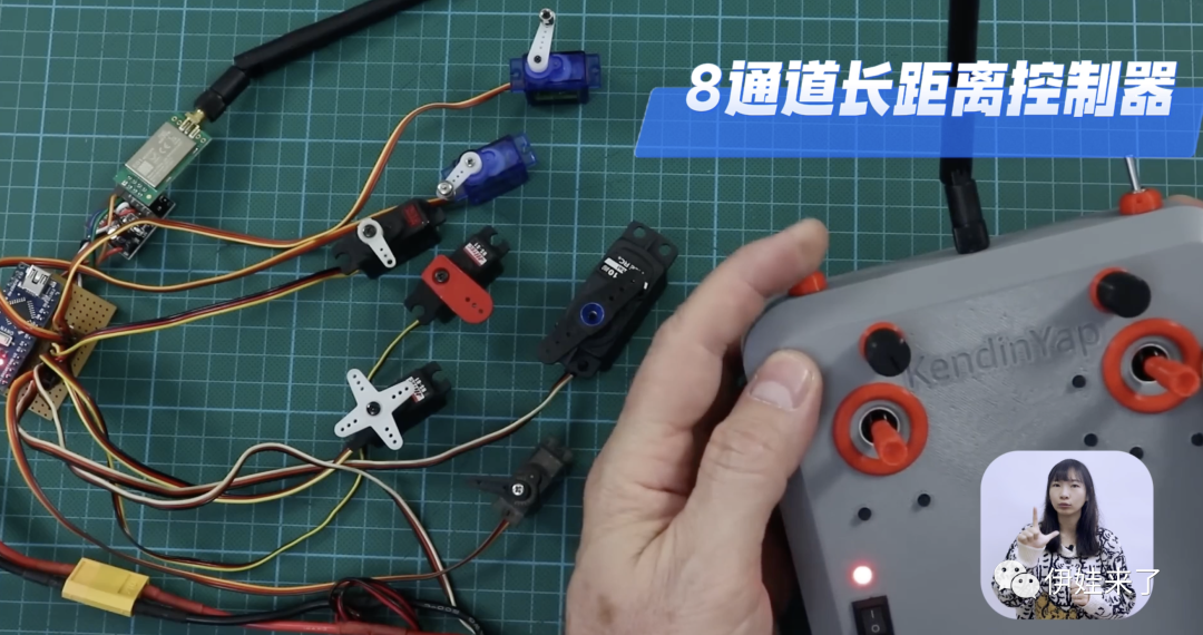
能2公里无线遥控的2.4GHz遥控器
描述

工具:
焊枪+焊锡
焊接夹具
螺丝刀
胶水
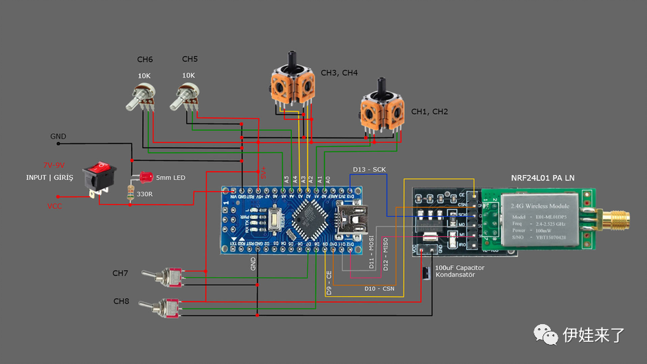
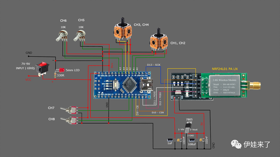
遥控器(发射器):
1 x NRF24L01+PA+LNA 2.4G发射接收通信模块
1 x 24L01无线模块转接板
1 x Arduino Nano板
1 x 100nF 100纳法电容
2 x双轴按键传感器
2 x 2档摇臂开关
1 x 7.4v 460Mah锂电池
1 x 330R电阻
1 x 10K电位器
2 x 15P 2.54mm单排排针插座
1 x 54mm X 20mm PCB板
1 x 7-9V的电池或者 1x 6节五号电池盒跟电池
若干:PCB板、电线、螺丝
// 8 Channel Transmitter (No Trim) | 8 Kanal Verici (Trim Yok)// Input pin A5
  #include   #include   #include   const uint64_t pipeOut = 000322;         // NOTE: The same as in the receiver 000322 | Alıcı kodundaki adres ile aynı olmalı  RF24 radio(9, 10);                       // select CE,CSN pin | CE ve CSN pinlerin seçimi
  struct Signal {  byte throttle;  byte pitch;  byte roll;  byte yaw;  byte aux1;  byte aux2;  byte aux3;  byte aux4;
};  Signal data;  void ResetData(){  data.throttle = 0;  data.pitch = 127;  data.roll = 127;  data.yaw = 127;  data.aux1 = 0;                       // Signal lost position | Sinyal kesildiğindeki pozisyon  data.aux2 = 0;  data.aux3 = 0;  data.aux4 = 0;}  void setup(){                                       //Configure the NRF24 module  | NRF24 modül konfigürasyonu  radio.begin();  radio.openWritingPipe(pipeOut);  radio.setAutoAck(false);  radio.setDataRate(RF24_250KBPS);    // The lowest data rate value for more stable communication  | Daha kararlı iletişim için en düşük veri hızı.  radio.setPALevel(RF24_PA_MAX);      // Output power is set for maximum |  Çıkış gücü maksimum için ayarlanıyor.  radio.stopListening();              // Start the radio comunication for Transmitter | Verici için sinyal iletişimini başlatır.  ResetData();
}                                      // Joystick center and its borders | Joystick merkez ve sınırları  int Border_Map(int val, int lower, int middle, int upper, bool reverse){  val = constrain(val, lower, upper);  if ( val < middle )  val = map(val, lower, middle, 0, 128);  else  val = map(val, middle, upper, 128, 255);  return ( reverse ? 255 - val : val );}  void loop(){                                     // Control Stick Calibration for channels  |  Her bir kanal için kumanda Kol Kalibrasyonları
  data.roll = Border_Map( analogRead(A3), 0, 512, 1023, true );        // "true" or "false" for signal direction | "true" veya "false" sinyal yönünü belirler  data.pitch = Border_Map( analogRead(A2), 0, 512, 1023, true );  data.throttle = Border_Map( analogRead(A1),570, 800, 1023, false );  // For Single side ESC | Tek yönlü ESC için  // data.throttle = Border_Map( analogRead(A1),0, 512, 1023, false ); // For Bidirectional ESC | Çift yönlü ESC için  data.yaw = Border_Map( analogRead(A0), 0, 512, 1023, true );  data.aux1 = Border_Map( analogRead(A4), 0, 512, 1023, true );        // "true" or "false" for change signal direction | "true" veya "false" sinyal yönünü değiştirir.  data.aux2 = Border_Map( analogRead(A5), 0, 512, 1023, true );        // "true" or "false" for change signal direction | "true" veya "false" sinyal yönünü değiştirir.  data.aux3 = digitalRead(7);  data.aux4 = digitalRead(8);
  radio.write(&data, sizeof(Signal));}
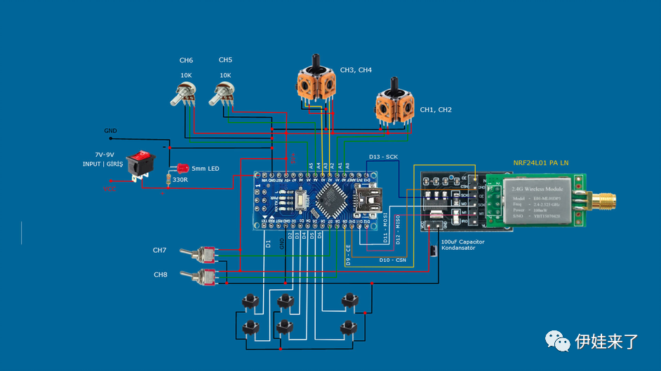
// 8 Channel Transmitter & Trims | 8 Kanal Verici ve Trimler
  #include   #include   #include   #include
  const uint64_t pipeOut = 000322;        // NOTE: The same as in the receiver 000322 | Alıcı kodundaki adres ile aynı olmalı  RF24 radio(9, 10);                      // Select CE,CSN pin | CE ve CSN pinlerin seçimi
 #define trimbut_1 1                      // Trim button 1 / Pin D1 #define trimbut_2 2                      // Trim button 2 / Pin D2 #define trimbut_3 3                      // Trim button 3 / Pin D3 #define trimbut_4 4                      // Trim button 4 / Pin D4 #define trimbut_5 5                      // Trim button 5 / Pin D5 #define trimbut_6 6                      // Trim button 6 / Pin D6
 int tvalue1 = EEPROM.read(1) * 4;        // Reading trim values from Eprom  |  Trim değerlerinin Epromdan okunması int tvalue2 = EEPROM.read(3) * 4; int tvalue3 = EEPROM.read(5) * 4;
  struct Signal {  byte throttle;  byte pitch;  byte roll;  byte yaw;  byte aux1;  byte aux2;  byte aux3;  byte aux4;};
  Signal data;  void ResetData(){  data.throttle = 512;                      // Signal lost position | Sinyal kesildiğindeki pozisyon  data.pitch = 127;  data.roll = 127;  data.yaw = 127;  data.aux1 = 0;  data.aux2 = 0;  data.aux3 = 0;  data.aux4 = 0;}  void setup(){                                         // Configure the NRF24 module  | NRF24 modül konfigürasyonu  radio.begin();  radio.openWritingPipe(pipeOut);  radio.setAutoAck(false);  radio.setDataRate(RF24_250KBPS);       // The lowest data rate value for more stable communication  | Daha kararlı iletişim için en düşük veri hızı.  radio.setPALevel(RF24_PA_MAX);         // Output power is set for maximum |  Çıkış gücü maksimum için ayarlanıyor.  radio.stopListening();                 // Start the radio comunication for Transmitter | Verici için sinyal iletişimini başlatır.  ResetData();
  pinMode(trimbut_1, INPUT_PULLUP);  pinMode(trimbut_2, INPUT_PULLUP);  pinMode(trimbut_3, INPUT_PULLUP);  pinMode(trimbut_4, INPUT_PULLUP);  pinMode(trimbut_5, INPUT_PULLUP);  pinMode(trimbut_6, INPUT_PULLUP);
  tvalue1= EEPROM.read(1) * 4;  tvalue2= EEPROM.read(3) * 4;  tvalue3= EEPROM.read(5) * 4;}
// Joystick center and its borders | Joystick merkez ve sınırları  int Border_Map(int val, int lower, int middle, int upper, bool reverse){  val = constrain(val, lower, upper);  if ( val < middle )  val = map(val, lower, middle, 0, 128);  else  val = map(val, middle, upper, 128, 255);  return ( reverse ? 255 - val : val );}  void loop(){
// Trims and Limiting trim values  |  Trimler ve Trim değerlerini sınırlandırma
  if(digitalRead(trimbut_1)==LOW and tvalue1 < 630) {    tvalue1=tvalue1+15;    EEPROM.write(1,tvalue1/4);    delay (130);  }  if(digitalRead(trimbut_2)==LOW and tvalue1 > 280){    tvalue1=tvalue1-15;    EEPROM.write(1,tvalue1/4);    delay (130);  }
  if(digitalRead(trimbut_3)==LOW and tvalue2 < 630) {    tvalue2=tvalue2+15;    EEPROM.write(3,tvalue2/4);    delay (130);  }  if(digitalRead(trimbut_4)==LOW and tvalue2 > 280){    tvalue2=tvalue2-15;    EEPROM.write(3,tvalue2/4);    delay (130);  }
    if(digitalRead(trimbut_5)==LOW and tvalue3 < 630) {     tvalue3=tvalue3+15;     EEPROM.write(5,tvalue3/4);     delay (130);  }  if(digitalRead(trimbut_6)==LOW and tvalue3 > 280){    tvalue3=tvalue3-15;    EEPROM.write(5,tvalue3/4);    delay (130);  }
// Control Stick Calibration for channels  |  Her bir kanal için kumanda Kol Kalibrasyonları
  data.roll = Border_Map( analogRead(A3), 0, tvalue1, 1023, true );       // "true" or "false" for signal direction | "true" veya "false" sinyal yönünü belirler  data.pitch = Border_Map( analogRead(A2), 0, tvalue2, 1023, true );  data.throttle = Border_Map( analogRead(A1),570, 800, 1023, false );    // For Single side ESC | Tek yönlü ESC için  // data.throttle = Border_Map( analogRead(A1),0, 512, 1023, false );   // For Bidirectional ESC | Çift yönlü ESC için  data.yaw = Border_Map( analogRead(A0), 0, tvalue3, 1023, true );  data.aux1 = Border_Map( analogRead(A4), 0, 512, 1023, true );  data.aux2 = Border_Map( analogRead(A5), 0, 512, 1023, true );  data.aux3 = digitalRead(7);  data.aux4 = digitalRead(8);  radio.write(&data, sizeof(Signal));}
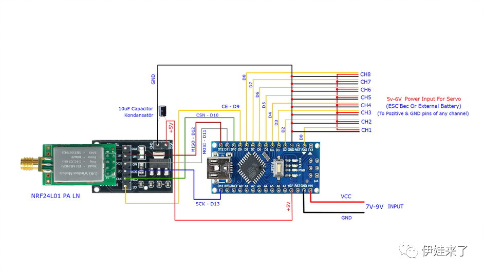
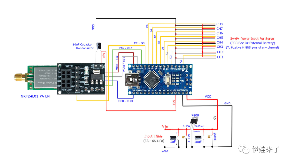
控制电机(接收器):
1 x NRF24L01+PA+LNA 2.4G发射接收通信模块
1 x 24L01无线模块转接板
1 x Arduino Nano板
1 x 100nF 100纳法电容
2 x 15P 2.54mm单排排针插座
3 x 8P 单排排针
1 x 54mm X 20mm PCB板
1 x 7-9V的锂电池
1 x 无刷电机+电子调速器(测试用,也可换舵机)
6 x 轻触开关
若干:PCB板、电线
//  8 Channel Receiver | 8 Kanal Alıcı
#include #include #include #include
int ch_width_1 = 0;int ch_width_2 = 0;int ch_width_3 = 0;int ch_width_4 = 0;int ch_width_5 = 0;int ch_width_6 = 0;int ch_width_7 = 0;int ch_width_8 = 0;
Servo ch1;Servo ch2;Servo ch3;Servo ch4;Servo ch5;Servo ch6;Servo ch7;Servo ch8;
struct Signal {
byte throttle;byte pitch;byte roll;byte yaw;byte aux1;byte aux2;byte aux3;byte aux4;};
Signal data;
const uint64_t pipeIn = 000322;RF24 radio(9, 10);
void ResetData(){
data.throttle = 0;data.roll = 127;data.pitch = 127;data.yaw = 127;data.aux1 = 0;                                              // Define the inicial value of each data input. | Veri girişlerinin başlangıç değerleridata.aux2 = 0;data.aux3 = 0;data.aux4 = 0;}
void setup(){                                                           // Set the pins for each PWM signal | Her bir PWM sinyal için pinler belirleniyor.  ch1.attach(0);  ch2.attach(2);  ch3.attach(3);  ch4.attach(4);  ch5.attach(5);  ch6.attach(6);  ch7.attach(7);  ch8.attach(8);
  ResetData();                                             // Configure the NRF24 module  | NRF24 Modül konfigürasyonu  radio.begin();  radio.openReadingPipe(1,pipeIn);  radio.setAutoAck(false);  radio.setDataRate(RF24_250KBPS);                          // The lowest data rate value for more stable communication  | Daha kararlı iletişim için en düşük veri hızı.  radio.setPALevel(RF24_PA_MAX);                            // Output power is set for maximum |  Çıkış gücü maksimum için ayarlanıyor.  radio.startListening();                                   // Start the radio comunication for receiver | Alıcı için sinyal iletişimini başlatır.
}
unsigned long lastRecvTime = 0;
void recvData(){while ( radio.available() ) {radio.read(&data, sizeof(Signal));lastRecvTime = millis();                                    // Receive the data | Data alınıyor}}
void loop(){recvData();unsigned long now = millis();if ( now - lastRecvTime > 1000 ) {ResetData();                                                // Signal lost.. Reset data | Sinyal kayıpsa data resetleniyor}
ch_width_1 = map(data.roll, 0, 255, 1000, 2000);ch_width_2 = map(data.pitch, 0, 255, 1000, 2000);ch_width_3 = map(data.throttle, 0, 255, 1000, 2000);ch_width_4 = map(data.yaw, 0, 255, 1000, 2000);ch_width_5 = map(data.aux1, 0, 255, 1000, 2000);ch_width_6 = map(data.aux2, 0, 255, 1000, 2000);ch_width_7 = map(data.aux3, 0, 1, 1000, 2000);ch_width_8 = map(data.aux4, 0, 1, 1000, 2000);

ch1.writeMicroseconds(ch_width_1);                          // Write the PWM signal | PWM sinyaller çıkışlara gönderiliyorch2.writeMicroseconds(ch_width_2);ch3.writeMicroseconds(ch_width_3);ch4.writeMicroseconds(ch_width_4);ch5.writeMicroseconds(ch_width_5);ch6.writeMicroseconds(ch_width_6);ch7.writeMicroseconds(ch_width_7);ch8.writeMicroseconds(ch_width_8);

}
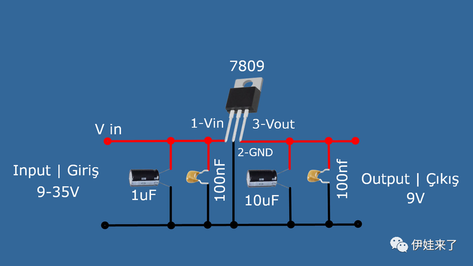
9V稳压器:
1 x 7809三级稳压管
1 x 1uF 微法电容
1 x 10uF微法电容
2 x 100nf 纳法电容
若干:PCB板、电线
5V稳压器:
1 x 7805三级稳压管
1 x 1uF 微法电容
1 x 10uF微法电容
2 x 100nf 纳法电容
若干:PCB板、电线
声明:本文内容及配图由入驻作者撰写或者入驻合作网站授权转载。文章观点仅代表作者本人,不代表电子发烧友网立场。文章及其配图仅供工程师学习之用,如有内容侵权或者其他违规问题,请联系本站处理。
举报投诉
-
基于芯岭技术XL2417D芯片的2.4G无线遥控器解决方案2026-01-15 1077
-
2.4GHz ISM射频前端芯片GC1103在无线遥控玩具中的应用2024-05-23 1881
-
应用在机顶盒遥控器中的2.4GHz无线芯片2024-02-29 2196
-
2.4G无线遥控器方案开发,稳定性强,可用于多种应用2024-01-18 5171
-
一种使用2.4GHz频段的无线遥控器方案开发2024-01-11 3246
-
宇凡微2.4G遥控器方案开发,灵活控制无需指向2023-08-01 2013
-
2.4G遥控器方案开发,无需指向也可以进行遥控2022-12-08 3656
-
2.4G遥控器解决方案2022-12-01 6803
-
一文弄懂无线遥控器2018-11-14 10743
-
2.4GHz无线射频芯片A7105应用2016-02-29 3293
-
基于STM32的开源微型四轴飞行器之传感器航模遥控器2015-04-10 23424
-
2.4GHz 无线VISTA遥控器实验开发系统2013-11-04 5243
-
万能遥控器设置方法_万能遥控器代码2012-09-14 192710
-
nRFready™2.4GHz 射频智能遥控器参考设计2012-03-24 4391
全部0条评论

快来发表一下你的评论吧 !
