

基于FPGA的图像处理算子/卷积核实现方法
电子说
描述
01
图像处理算子概述
FPGA最大的优势体现在其低功耗和并行运算的特点上,数字图像蕴含数据量大,采用FPGA可以在保证低功率运算的情况下,有效提高图像算法的实时性。
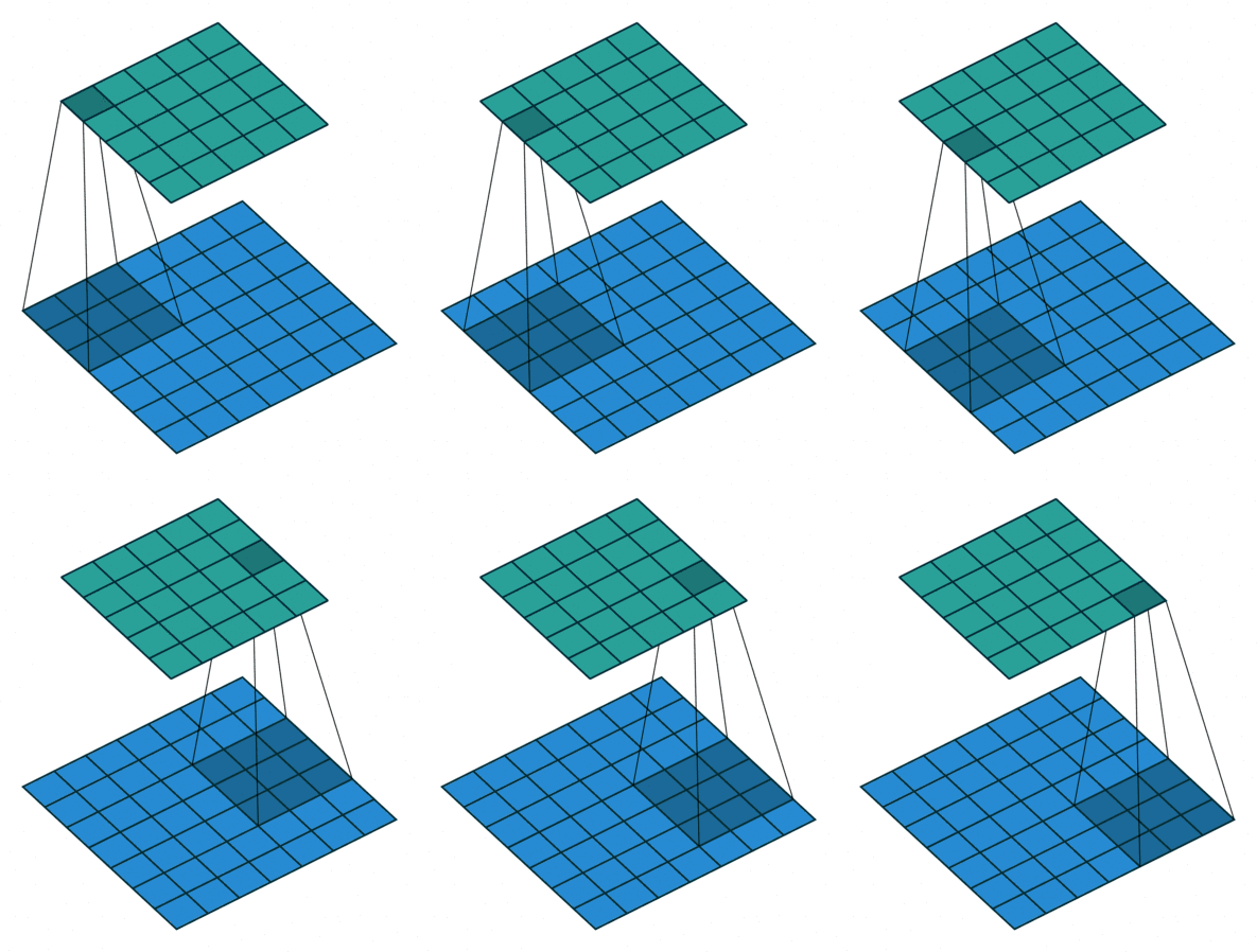
图像处理算子/卷积核是并行运算最常采用的手段——图像处理算子/卷积核对图像矩阵自左向右、自上到下循环线性运算,循环过程各运算相互独立,不存在顺序依赖。
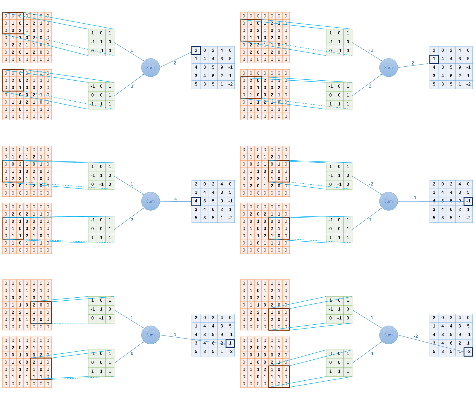
掌握基于FPGA的图像处理算子/卷积核实现方法,对提升图像算法实时性和神经网络运算具有重要意义。
1.1 图像处理算子概念
图像处理算子是对图像进行处理时所用到的算子,根据计算机视觉(Computer Vision)图像内容表示方法不同,可划分为基于全局特征的图像内容表示方法下的全局特征描述算子和基于局部特征的图像内容表示方法下的局部特征描述算子。尽管根据图像不同特征设计出不同的图像算法,但全局特征和局部特征描述算子在本质上没有明显差异。
类似于卷积神经网络,当算法设计采用多级/层运算时,每级/层采用的图像处理算子/卷积核的尺寸越小,越利于运算深度的扩展。因此,本文主要以局部特征描述算子为主进行介绍。
图像处理算子设计通常要求具备重复性、判别性、局部不变性、富含信息、量化描述和精确高效等特性。根据图像处理算子的应用功能可分为微分算子、基于矩的描述算子、基于滤波器的描述算子和基于分布统计的描述算子等。因此,图像处理算子在图像增强领域使用较为广泛。
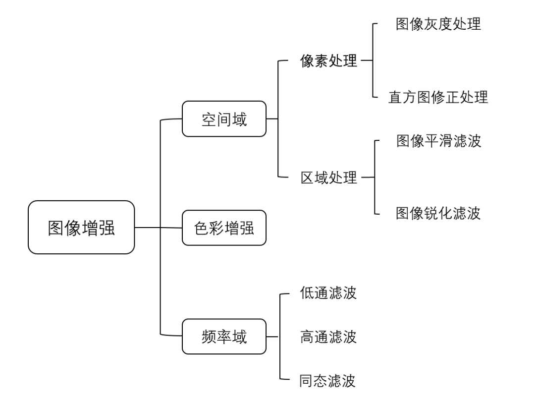
1.2 图像处理算子功能
图像处理算子/卷积核设计尺寸通常采用奇数:3×3、5×5、7×7...从而通过中心点(central pixel)确定像素位置信息,便于以中心点为基准实现算子滑动运算。
图像处理算子/卷积核设计尺寸在特定情况下也会采用偶数:基于分布统计的描述算子——SIFT描述算子采用4×4×8维描述图像的尺度不变特征。
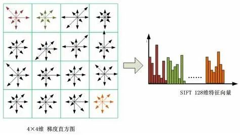
由于奇数尺寸图像处理算子/卷积核应用广泛,这里以一阶微分算子为例简要介绍图像处理算子的工作原理:
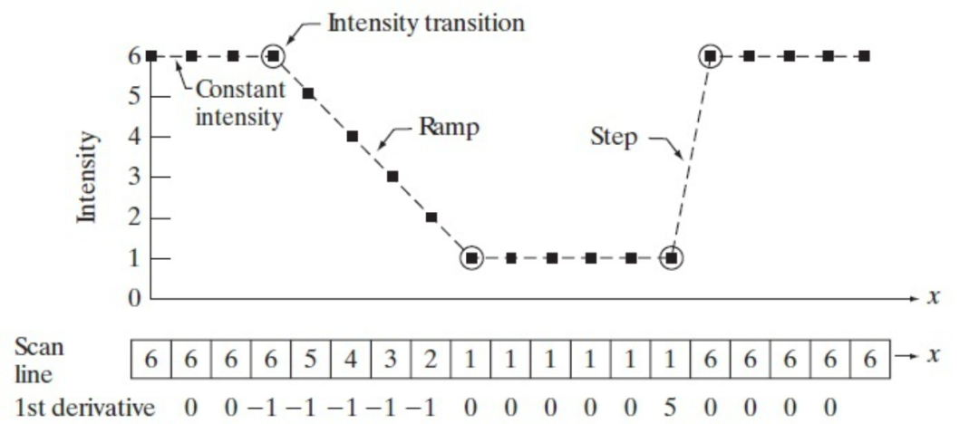
对图像进行上述一阶微分运算:

相应的一阶微分算子G满足:
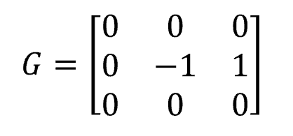
利用一阶微分算子G对数字图像循环遍历,得到一阶微分处理后的图像结果:
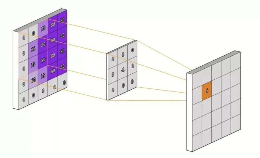
微分运算常用于研究相邻像素差异,主要应用在图像边缘提取操作中,具体原理在微分算子中进行具体介绍。
02
图像处理算子原理
图像处理算子根据应用功能不同可主要分为微分算子、基于矩的描述算子、基于滤波器的描述算子和基于分布统计的描述算子四类。本节以微分算子为例,介绍图像处理算子的设计与原理。
2.1 离散数据微分运算
微分算子用于对图像进行微分运算,通常用于实现边缘检测和图像二值化等功能。对于连续函数的微分运算通常定义为:

相应地,二元函数的偏微分运算定义为:
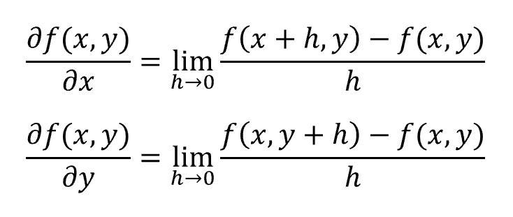
数字图像像素是一组二维离散数据,h无法趋近于无穷小,因此其导数采用差分方差的形式近似:
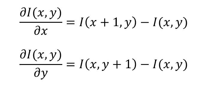
差分方差根据不同形式可分为:
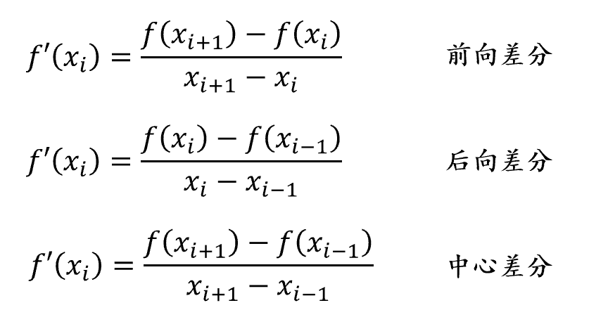
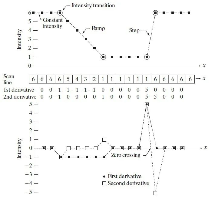
不同差分形式求解数据微分运算可能存在一定的误差,通常根据不同的应用场景灵活选择差分形式。以一维离散数据为例,利用差分方差求解一阶微分和二阶微分的结果可表示为:
2.2 微分算子设计原理
基于离散数据的微分运算方程,以3×3算子为例解释数字图像微分算子的设计原理。为便于后续原理解释,约定对于以(x,y)为中心像素的3×3数字图像区域,各像素按坐标位置进行命名:
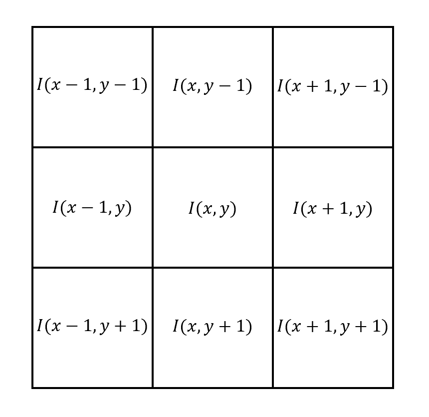
微分算子对数字图像求微分操作通过矩阵乘法实现:
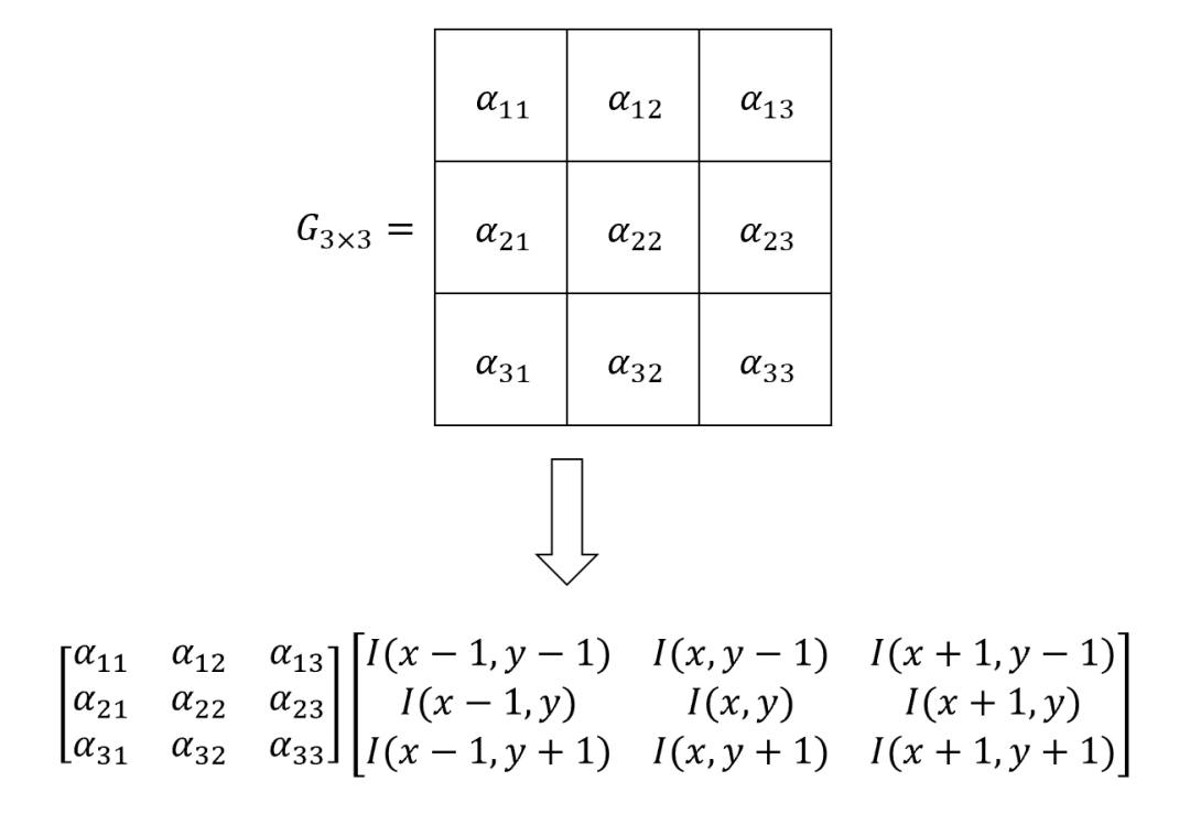
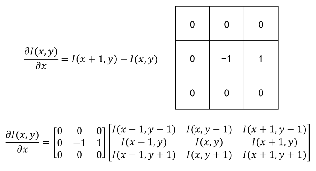
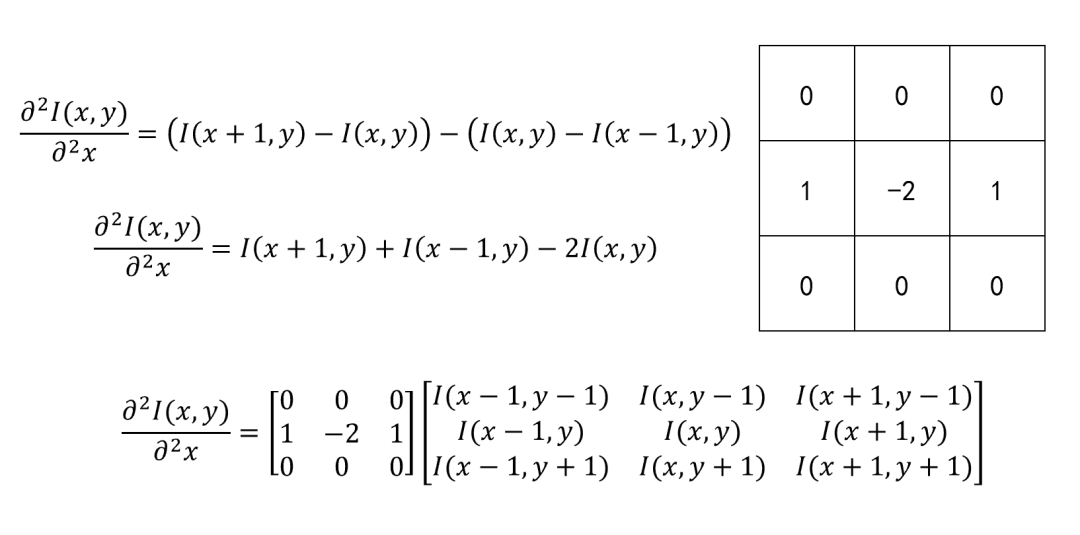
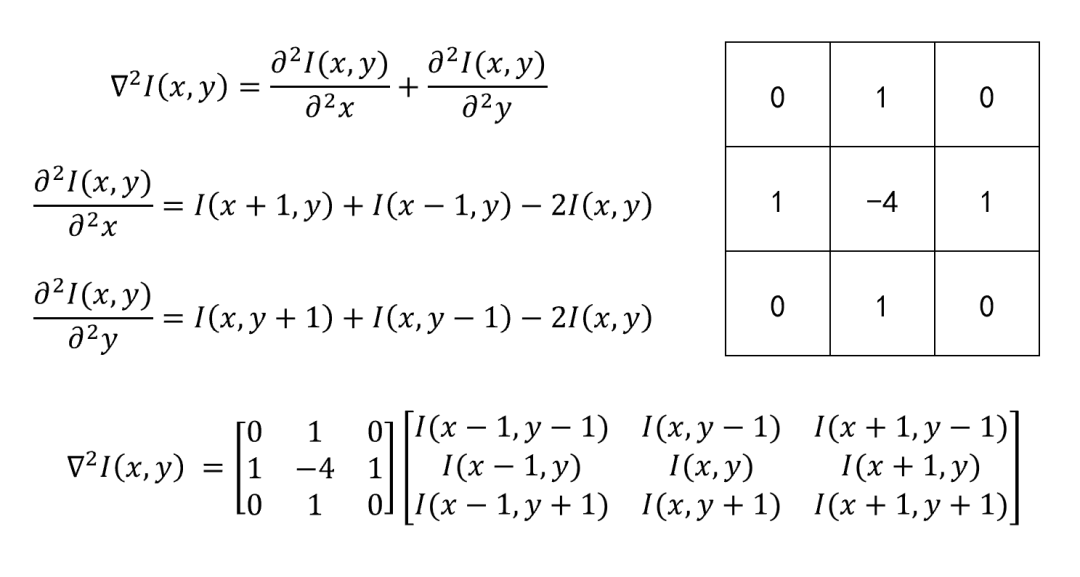
因此,根据不同的差分形式微分方程,可以构建不同的图像微分算子。这里给出三种典型的微分算子设计:
1. 一阶微分算子设计:
2. 二阶微分算子设计:
3. 拉普拉斯算子设计:
2.3 微分算子实现效果
以拉普拉斯算子为例,对拍摄的原始图像利用拉普拉斯算子进行微分处理后,得到边缘提取后的图像,将提取边缘与原始图像相加,可以对原始图像完成锐化操作。
03
图像处理算子实现
并行运算是FPGA图像处理的主要优势,通过图像处理算子的方式对图像区域并行处理,可以有效提高算法运行速率,提升系统的实时性。
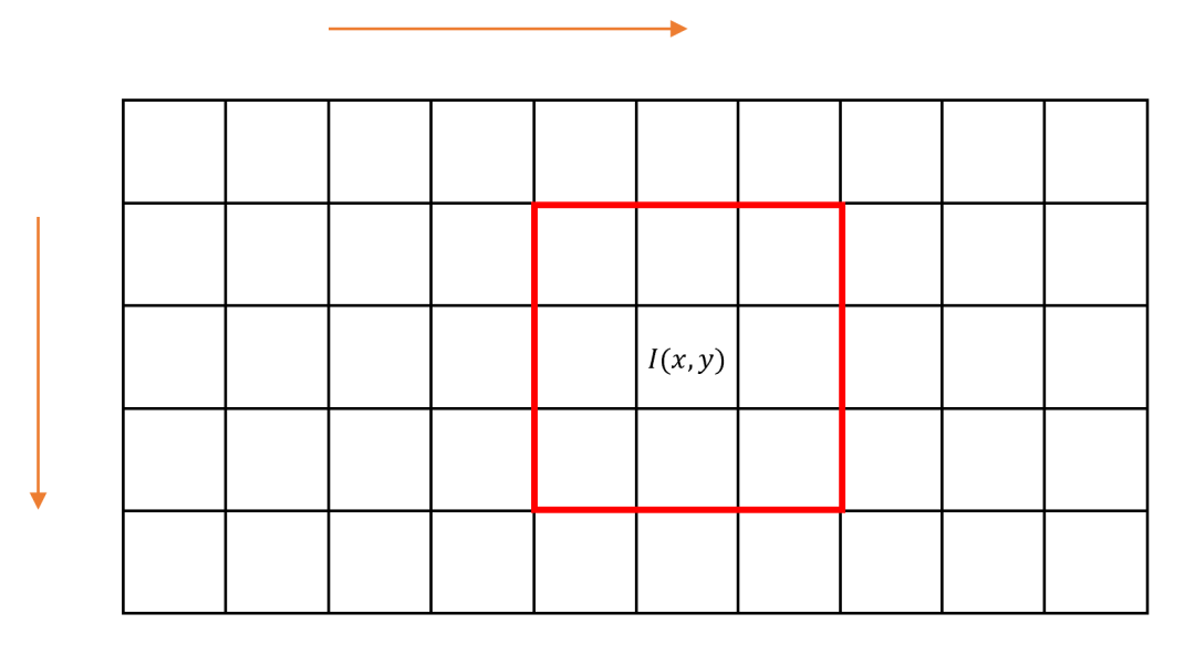
以3×3区域为例,由于图像数据通常按照从上到下、从左到右的顺序逐个像素点进行扫描,所以无法直接读取中心像素周围3×3范围内的所有数据。因此,本节采用FIFO缓存的方式,直接从中心像素提取相邻3×3区域内的像素值,为后续图像处理算法提供基础模板。
3.1 图像处理算子实现策略
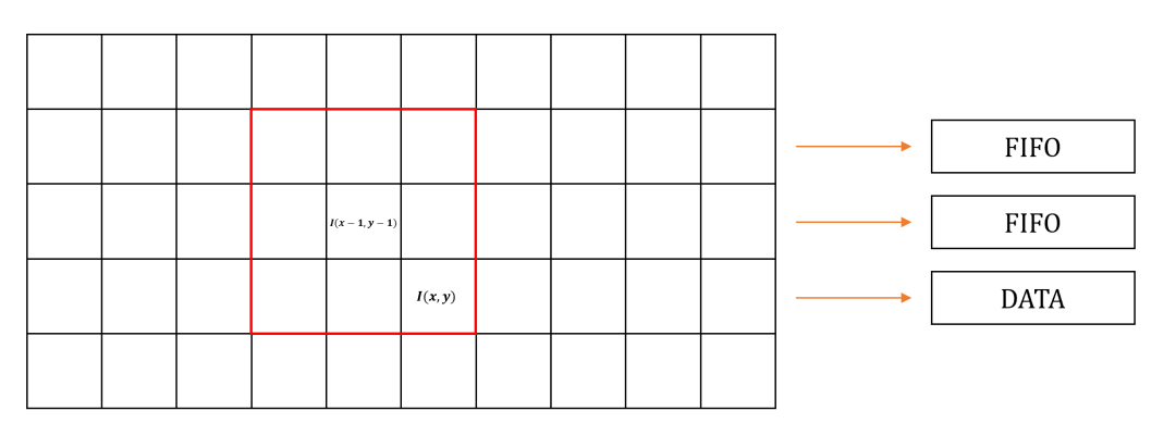
由于数字图像数据是逐行逐列、逐个像素读取,考虑读取一个3×3区域内的数据,需要缓存辅助实现。因此,利用两个FIFO存储当前读取像素位置前两行的数据,如下图所示。此时,在读取像素的同时可以按照坐标关系,从FIFO中读出3×3区域内的其他所有像素值。需要注意的是,这种方法所读取到的区域并非以当前读取像素为中心,而是以I(x-1,y-1)为中心像素的3×3区域。
读取过程中存在的一个值得关注问题是边界像素的处理。例如,在扫描第一个数据时,相邻3×3区域像素需要包括图中灰色部分的五个像素值,而这五个像素值实际是不存在的。如果边界像素处理不好,图像处理效果可能会大打折扣:以微分运算为例,当边缘像素处理不合适时,图像周围可能会出现明显边缘特征,对实际边缘提取操作造成严重影响。
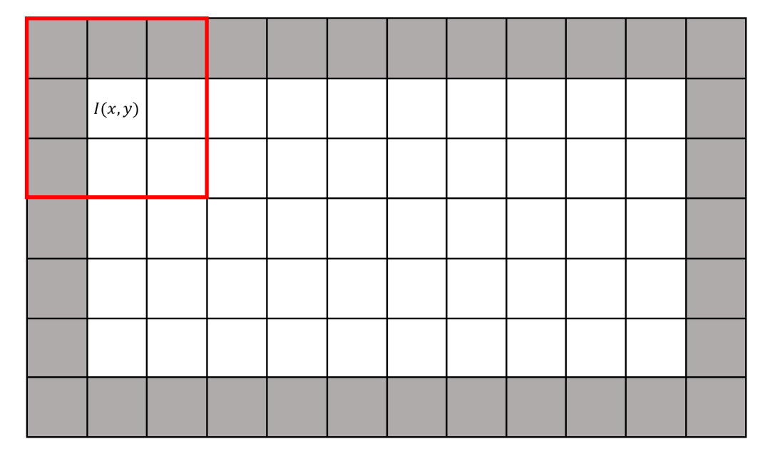
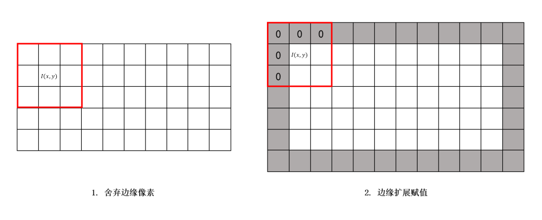
对于边缘像素的处理通常根据应用场景的不同,会采用不同的处理方法以提高算法的性能,最常用的处理方法主要有两种:
舍弃边缘像素值,保证算子不会超出图像区域;
扩展边缘(图中灰色部分)赋初值0或255(8 bit数据)。
3.2 图像处理算子Verilog代码
Verilog编写图像算子生成代码cx_operator.v,并导入FIFO Generator IP核用于缓存前两行的图像数据,以sim_tb.v为仿真文件输出波形验证算子的正确性。
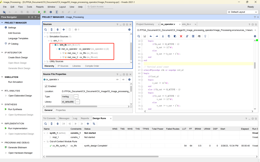
各模块代码如下:
1. 算子生成模块 cx_operator.v:
`timescale 1ns / 1ps
//////////////////////////////////////////////////////////////////////////////////
// Company: Cascatrix
// Engineer: Carson
//
// Create Date: 2023/04/02
// Design Name: Image_Processing_Operator
// Module Name: cx_operator
// Tool Versions: v1.0
// Description: Generate image processing operator
//
//////////////////////////////////////////////////////////////////////////////////
module cx_operator(
input wireclk,
input wirerst_n,
inputwireen,
inputwire [7:0]data,
output reg [7:0]operator_11,
output reg [7:0]operator_12,
output reg [7:0]operator_13,
output reg [7:0]operator_21,
output reg [7:0]operator_22,
output reg [7:0]operator_23,
output reg [7:0]operator_31,
output reg [7:0]operator_32,
output reg [7:0]operator_33
);
parameter H_ACTIVE = 640;
parameter V_ACTIVE = 480;
reg [10:0]h_cnt;
reg [10:0]v_cnt;
reg fifo_1_wr_en;
reg fifo_1_rd_en;
wire [7:0]fifo_1_in;
wire [7:0]fifo_1_out;
reg fifo_2_wr_en;
reg fifo_2_rd_en;
wire [7:0]fifo_2_in;
wire [7:0]fifo_2_out;
// Horizontal pixel count
always@(posedge clk or negedge rst_n)
begin
if(!rst_n)
h_cnt <= 11'b0;
else if(en)
begin
if(h_cnt == H_ACTIVE - 1)
h_cnt <= 11'b0;
else
h_cnt <= h_cnt + 1'b1;
end
end
// Vertical pixel count
always@(posedge clk or negedge rst_n)
begin
if(!rst_n)
v_cnt <= 11'b0;
else if(h_cnt == H_ACTIVE - 1)
begin
if(v_cnt == V_ACTIVE - 1)
v_cnt <= 11'b0;
else
v_cnt <= v_cnt + 1'b1;
end
end
// Write enable signal of the first FIFO
always@(posedge clk or negedge rst_n)
begin
if(!rst_n)
fifo_1_wr_en <= 1'b0;
else if(v_cnt < V_ACTIVE - 1)
fifo_1_wr_en <= en;
else
fifo_1_wr_en <= 1'b0;
end
// Write enable signal of the second FIFO
always@(posedge clk or negedge rst_n)
begin
if(!rst_n)
fifo_2_wr_en <= 1'b0;
else if(v_cnt > 0)
fifo_2_wr_en <= en;
else
fifo_2_wr_en <= 1'b0;
end
// Read enable signal of the first FIFO
always@(posedge clk or negedge rst_n)
begin
if(!rst_n)
fifo_1_rd_en <= 1'b0;
else if(v_cnt > 0)
fifo_1_rd_en <= en;
else
fifo_1_rd_en <= 1'b0;
end
// Read enable signal of the second FIFO
always@(posedge clk or negedge rst_n)
begin
if(!rst_n)
fifo_2_rd_en <= 1'b0;
else if(v_cnt > 1)
fifo_2_rd_en <= en;
else
fifo_2_rd_en <= 1'b0;
end
// FIFO data in
assign fifo_1_in= data;
assign fifo_2_in= fifo_1_out;
// Instance of the first FIFO
cx_fifo inst_row_1(
.clk(clk),
.srst(!rst_n ),
.din (fifo_1_in),
.wr_en(fifo_1_wr_en),
.rd_en(fifo_1_rd_en),
.dout (fifo_1_out),
.full (),
.empty()
);
// Instance of the second FIFO
cx_fifo inst_row_2(
.clk(clk),
.srst(!rst_n ),
.din (fifo_2_in),
.wr_en(fifo_2_wr_en),
.rd_en(fifo_2_rd_en),
.dout (fifo_2_out),
.full (),
.empty()
);
// 3×3 operator generation
always@(negedge clk or negedge rst_n)
begin
if(!rst_n)
begin
operator_11<= 8'd0;
operator_12<= 8'd0;
operator_13<= 8'd0;
operator_21<= 8'd0;
operator_22<= 8'd0;
operator_23<= 8'd0;
operator_31<= 8'd0;
operator_32<= 8'd0;
operator_33<= 8'd0;
end
else
begin
operator_11<= operator_12;
operator_12<= operator_13;
operator_13<= fifo_2_out;
operator_21<= operator_22;
operator_22<= operator_23;
operator_23<= fifo_1_out;
operator_31<= operator_32;
operator_32<= operator_33;
operator_33<= data;
end
end
endmodule
2. 仿真模块 sim_tb.v:
`timescale 1ns / 1ps
//////////////////////////////////////////////////////////////////////////////////
// Company: Cascatrix
// Engineer: Carson
//
// Create Date: 2023/03/02
// Design Name: Image_Histogram_Statistic
// Module Name: sim_tb
// Tool Versions: v1.0
// Description: Image output simulation
//
//////////////////////////////////////////////////////////////////////////////////
module sim_tb(
);
reg clk;
reg rst_n;
reg [31:0] pixel_cnt;
wire hsyn;
wire vsyn;
wire de;
wire [7:0] gray_data;
integer image_txt;
parameter PIXEL_TOTAL = 1920*1080;
//parameter PIXEL_TOTAL = 1680*1050;
//parameter PIXEL_TOTAL = 1280*1024;
//parameter PIXEL_TOTAL = 1280*720;
//parameter PIXEL_TOTAL = 1024*768;
//parameter PIXEL_TOTAL = 800*600;
//parameter PIXEL_TOTAL = 640*480;
cx_top inst_cx_top
(
.clk (clk ),
.en (de ),
.hsyn (hsyn ),
.vsyn (vsyn ),
.gray_data (gray_data )
);
always #1 clk = ~clk;
initial
begin
clk = 1;
rst_n = 0;
#100
rst_n = 1;
end
initial
begin
image_txt = $fopen("D:/FPGA_Document/CX_
Document/CX_Image/03_Image_histogram_statistic
/image_src/image_out.txt");
end
always@(posedge clk or negedge rst_n)
begin
if(!rst_n)
begin
pixel_cnt <= 0;
end
else if(de)
begin
pixel_cnt = pixel_cnt + 1;
$fwrite(image_txt,"%h ",gray_data);
end
end
always@(posedge clk)
begin
if(pixel_cnt == PIXEL_TOTAL && ~vsyn)
begin
$display("CX: image_out.txt is output completed successfully! %t", $realtime, "ps");
$fclose(image_txt);
$stop;
end
end
endmodule
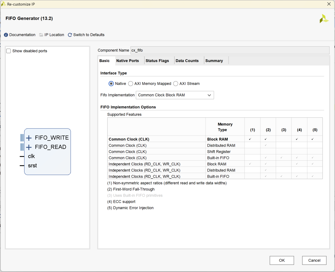
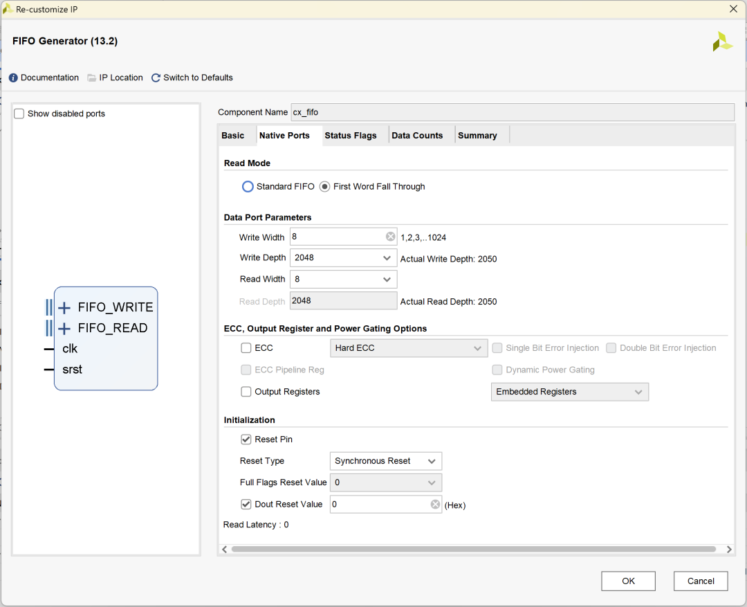
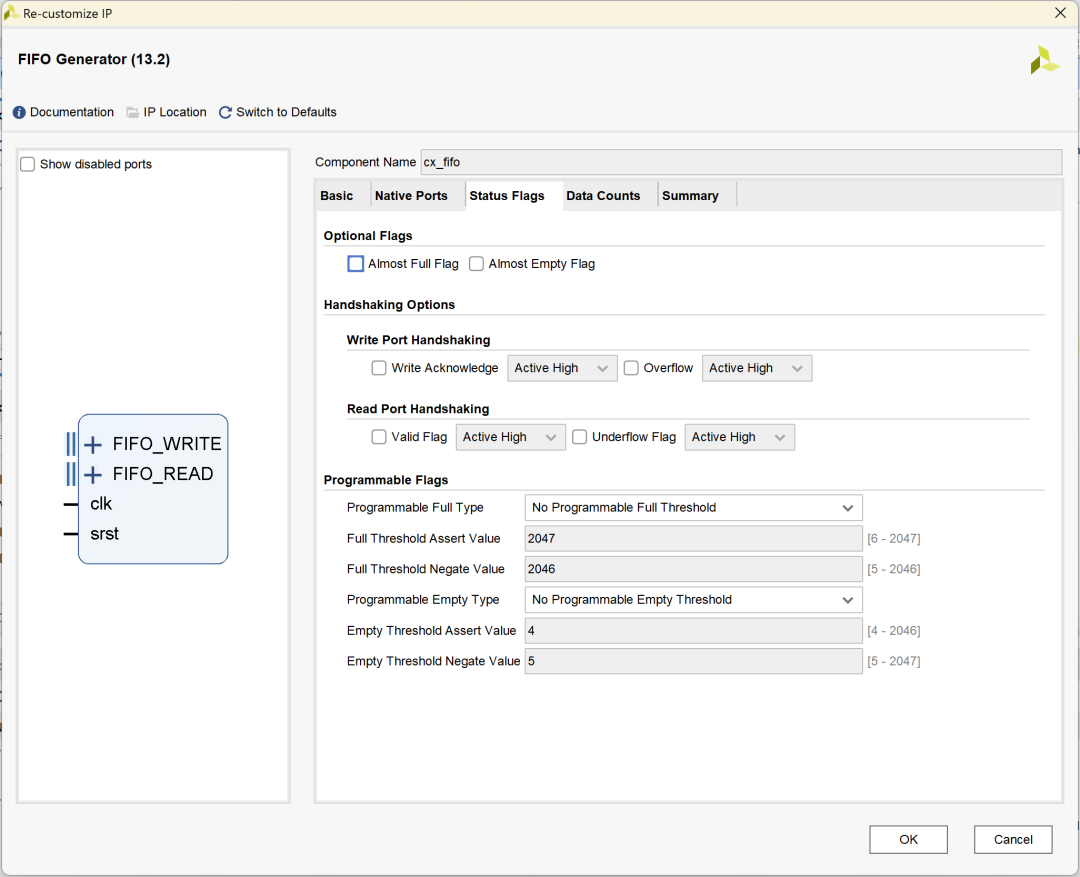
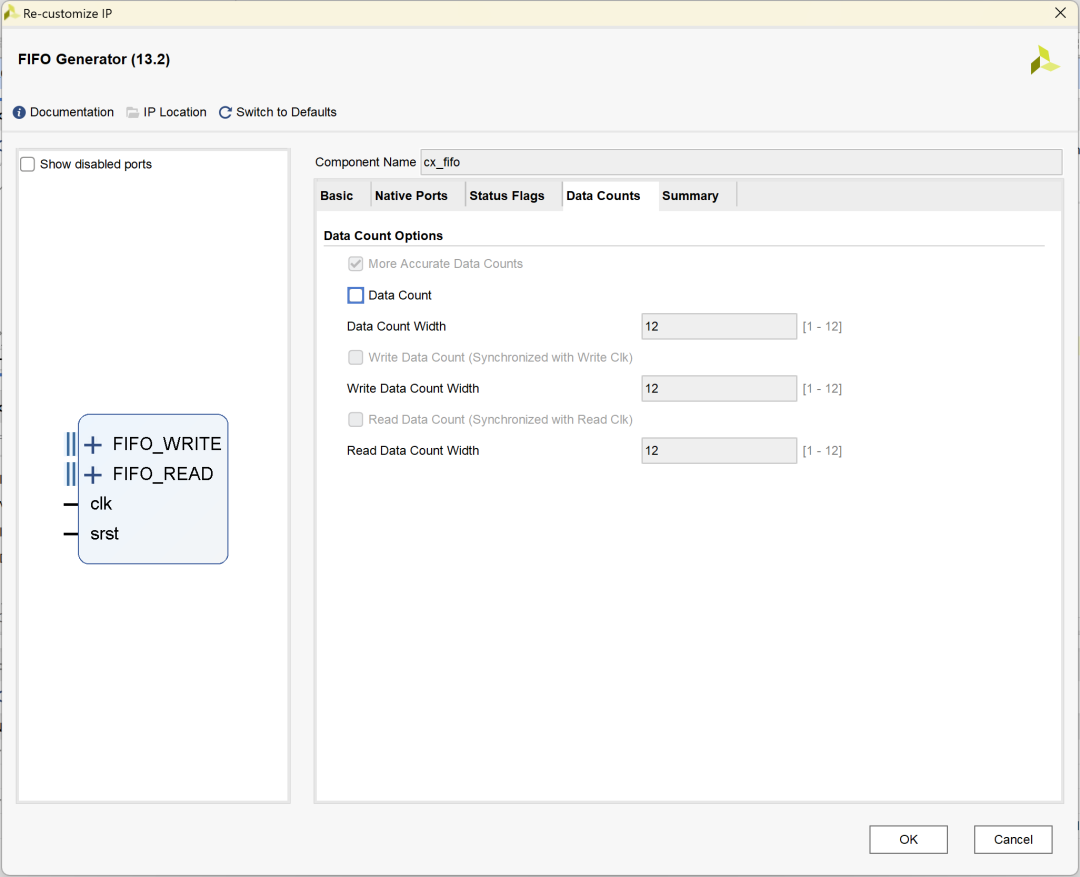
3. FIFO Generator IP配置:
Basic配置FIFO为Native接口类型:
Native Ports配置FIFO位宽为8、深度为2048,使能Reset Pin:
Status Flags可以不做配置:
Data Counts可以不做配置:
3.3 测试数据生成Matlab代码
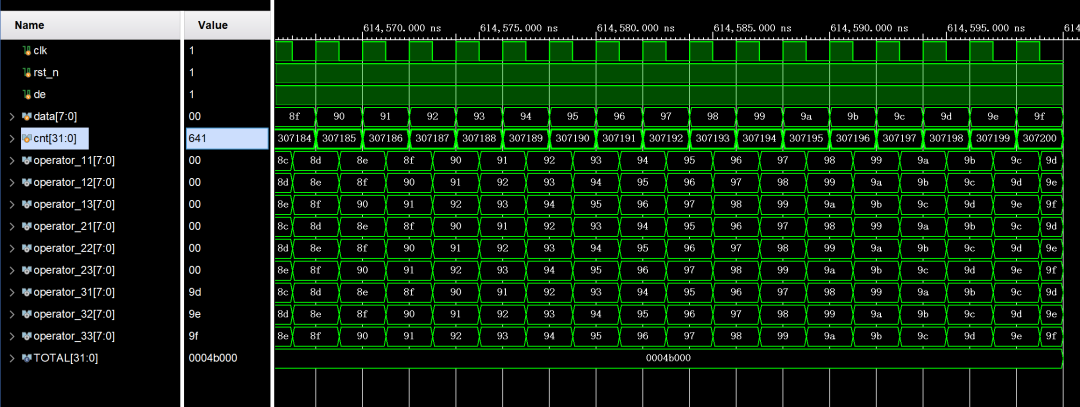
为便于算子的仿真测试,利用Matlab生成尺寸为640×480的测试数据data_640_480.txt,数据内容以0~160进行循环,每行循环640/160=4次,每列重复循环。当仿真波形中,算子各行相应列数据相同时,可以验证算子时序正确。
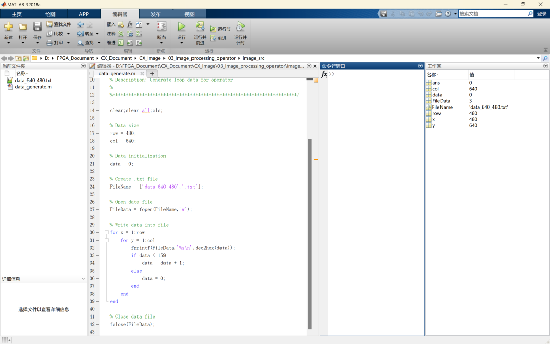

Matlab测试数据生成代码:
%**********************************************************************
% -------------------------------------------------------------------
% Company: Cascatrix
% Engineer: Carson
%
% Create Date: 2023/04/02
% Design Name: data_generate
% Module Name: data_generate
% Tool Versions: v1.0
% Description: Generate loop data for operator
%-------------------------------------------------------------------
%*********************************************************************/
clear;clear all;clc;
% Data size
row = 480;
col = 640;
% Data initialization
data = 0;
% Create .txt file
FileName = ['data_640_480','.txt'];
% Open data file
FileData = fopen(FileName,'w');
% Write data into file
for x = 1:row
for y = 1:col
fprintf(FileData,'%s ',dec2hex(data));
if data < 159
data = data + 1;
else
data = 0;
end
end
end
% Close data file
fclose(FileData);
3.4 仿真结果分析
仿真波形验证结果如下:
1. 当写入第一行数据前,所有算子像素值置0,第一行数据直接从operator3_中读出;
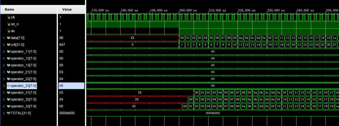
2. 当写入第二行数据时,第一行数据存入FIFO1中,并从operator2_中读出,第二行数据直接从operator3_中读出;
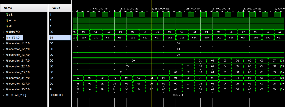
3. 当写入第三行数据时,第一行数据存入FIFO2中,并从operator1_中读出,第二行数据存入FIFO1中,并从operator2_中读出,第三行数据直接从operator3_中读出;
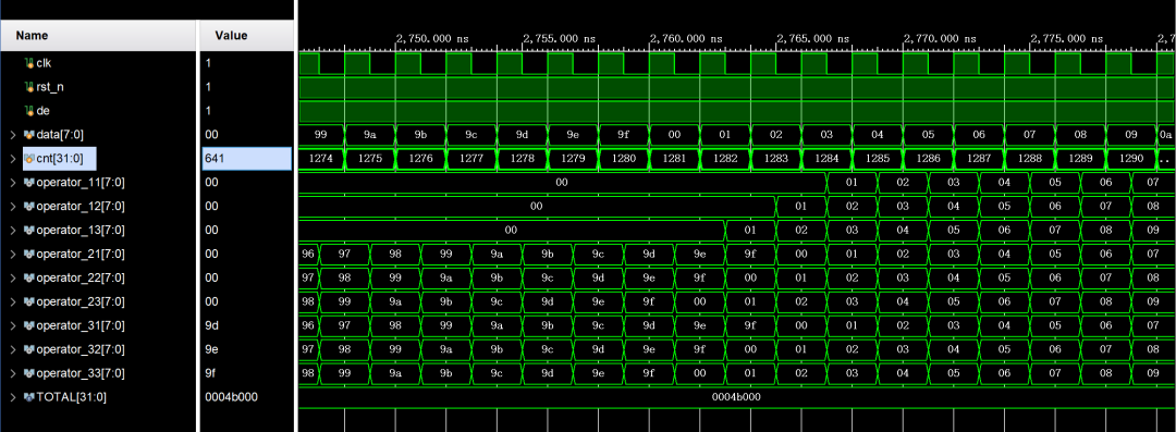
4. 按以上方式循环遍历数据,波形算子输出始终满足operator1x = operator2x = operator3x,即测试数据逐行对齐,验证3×3算子生成的时序无误,实现从一个像素读取相邻像素值的功能。
审核编辑:刘清
-
 jf_89091035
2023-05-18
0 回复 举报您好,cx_top文件方便分享一下吗?非常感谢 收起回复
-
FPGA图像处理基础----实现缓存卷积窗口2025-02-07 1520
-
FPGA设计经验之图像处理2024-06-12 3187
-
荐读:FPGA设计经验之图像处理2023-06-08 5916
-
Laplacian算子的硬件实现及结果2022-07-21 1611
-
Laplacian算子的FPGA实现方法2020-06-16 3874
-
基于FPGA而实现的视频图像处理算法2019-09-13 4097
-
一种基于FPGA的实时视频图像处理算法研究与实现2019-06-28 3874
-
基于FPGA的Sobel边缘检测的实现2017-08-29 5384
-
FPGA信号处理算法设计、实现以及优化(南京)2016-12-26 809
-
基于FPGA的数字信号处理算法研究与高效实现2016-08-29 800
-
LOG算子在FPGA中的实现2011-05-16 1270
-
基于DSP和FPGA的通用图像处理平台设计2010-12-25 614
-
基于Simulink的视频与图像处理算法的快速实现2010-04-29 827
-
拉普拉斯算子的FPGA实现方法2010-02-11 1691
全部0条评论

快来发表一下你的评论吧 !

